DIY 6FET Controller help

I don't think this circuit will work.
I was thinking to myself during a 2hour bicycle ride after work and the 100pF cap(or what ever value it will be) connected to the constant current supply will always be charged and will trigger the op-amp all the time. I need to short the cap out until the gate drive to the MOSFET goes hi and then let the cap charge via the 250uA
constant current supply.

I better test these ideas before posting anymore dodgy circuits.
 
SjwNz said:
I'm working on a workaround for this, using a high speed comparator for more accurate detection of the voltage drop across the MOSFETs.
Futterama
I came up with this today, is this similar to what you were planing ?
No, not quite. You have a few challenges there.
First, the DESAT pin must not go above 10V according to the datasheet.
Second, what comparator is that? I was not able to find any high speed comparators that could run straight from 15V. And with high speed I mean the propagation delay is less than 500ns and less than 100ns is even better, to keep the overcurrent duration on the MOSFET low.
I'm still in the process of figuring the last details out, but you must also remember that the DESAT pin has it's own 250µA current source, so why not just use that?

The attached schematic is not finished, but my thinking is to add a zener diode that would take the DESAT pin above the threshold, like 8V. Then the open drain output comparator will pull the DESAT pin below threshold when no overcurrent condition exist. When an overcurrent condition exists, the comparator will detect that, and release the DESAT pin and the voltage here would rise above the threshold, triggering the 333J DESAT protection.
Does it make sense? I haven't tested it yet, and I haven't done any resistor value calculations yet. But I have some 5V, 47ns, open drain output comparators on their way for testing and when they arrive, I will do some testing.
 

Attachments

  • desat_not_finished.png
    desat_not_finished.png
    63.4 KB · Views: 2,349
Avago has a good application note regarding the desaturation detection which is worth reading:

http://www.avagotech.com/docs/AV02-0258EN

Oh, and also the attached document is a very good help, it also uses a comparator for detection, but it does not regard a gate driver with built-in DESAT detection, so we will need to invent the interface from comparator to DESAT pin ourselves.
 

Attachments

  • Mosfet Desaturation Detection - 2010.pdf
    3.6 MB · Views: 111
As far as your current limiting goes, it might be more complicated than it needs to be and not react fast enough to save the FETs from frying. Its ok to have the shunt between ground and the low side fets, because while the average voltage across it will be the average battery current, not motor current. The instantaneous voltage during the PWM on-time will correspond to the instantaneous motor current, which is what you really care about. The current will reach a peak at the end of the PWM on period, then fall at a rate corresponding to the motor's resistance and inductance. For current limiting you should just pick your peak motor current and set the comparator accordingly. When the comparator output turns on, just set the PWM output to low for the remainder of the PWM period. This way you're controlling current on a cycle by cycle basis and never let the current go over your limit.
 
Thanks for the info dirty_d, my multi comparator method was a bit rubbish and I have decided to use a dsPIC30F4010 which has a very fast AD convertor so I can remove the comparators.

Futterama
I tested the Desat threshold voltage levels last night and found that the 9 chips I tested were very very close which was good.
but not so good was the threshold dropped by 0.2V when I heated the driver up to approx 50°C . this will lower the desat trigger current
so I would have to set a much higher Desat trigger current when the controller is cold to make sure the desat current does not get to low and triggers all the time
when the controller heats up. Maybe the driver chip will never get this hot, but its still not very good for the very low RDSon for the IRFP4468 which is what I am using. I did not test the Desat threshold voltage a low temperature.
I am going to use some of my circuit and some of yours for my next design and build a test circuit as I have a much better understanding of it
after playing with desat on the 333J last night. The comparator I am going to use has a propagation delay of
300nS and can run it from the 15V supply, hope this is fast enough.
 
SjwNz, the gate drivers will get hotter due to the power dissipation of the driving elements inside the chip. Unfortunately I cannot see any values in the ACPL-333J datasheet for the ON-state resistance of the switches, otherwise I could calculate the power dissipation from the switching frequency and input capacitance of the MOSFET.

Can you please give the part number of that comparator?
 
Using the circuit diagram Desat V1-01.pdf I have done this little layout for 1 gate driver and I have notes on the file
where I am not sure about some sections. If anyone has any input on this that would be great
I still have to do the digital input section.
I have forgotten how to import a schematic with nets, into the PCB program so better learn how to do that again
so I haven't got any component designators at this stage but will be adding them soon.

View attachment Desat V1-01 PCB.pdf
 
I'm not sure what you guys are doing with all that extra stuff on the desat circuit, it's not needed for desat to do it's job. Just tune it by hand after you build it (this is what I did and it can be done in about 30 mins if you have the parts on hand). The less extra stuff in a gate driver circuit, the less there is to go wrong in a very critical system.

First let's discuss the purpose of desat and I can sum it up in a very short example.
Holy shit something really really bad just happened... STOP!
Desaturation detection is something that is nice to have, but it's only there for when things go really bad, things you should have designed to avoid happening in the first place. The perfect desaturation circuit is one that is in place, has been tested and never ever gets used in it's entire life.

The amount of blanking time and how quickly the current rises in your load play the biggest role in how long the period is until it shuts down. Desat should only be active for a catastrophic event. That means the MOSFET only has to survive the high current situation for a few uS.

In order to fully understand if the desat can do it's job, you need to look at the data sheets and establish some parameters and then do the math.
We'll use and IRFP4468 for this example since you mentioned using it. I'll say it takes 5uS total until desat kicks in and shuts down the D-S connection based on experience with my TD350E (I've seen as short as 4uS).

1. RDSon worst case scenarios, 2.0mohm min and 2.6mOhm max. we know there is variation so we'll use 2.3mOhm for our calculations since the manufacturer is guaranteeing these tolerances are the range.
2. Maximum pulse current the MOSFET can sustain: 1120A (not says this is limited by max junction temperature which is 175c)
3. Find max amps for our wosrt case scenario of Tj= 175c, 5uS time. How many amps can the MOSFET handle? To the data sheet
3. Fig 8. Look up Vds vs Id at Tj=175, this is Fig. 8 on the spec sheet. Test condition is 25c on the case and 175 on the die, single pulse. We need a 5uS sec rating so we go to the area shorter than 100uS.
4. Fig 8. Looks like anything under 5uS is ok up to 1100A even. Yes this will have to be derated for case temp, but even if we derate and say 500A, we still have a very large range.
5. Now we have a good idea that the MOSFET will probably survive a 500A for at least 5uS under very bad conditions.
6. We need to know how much the RDSon changes from one temp to another, because this will effect the desat current. We'll say the Tj operating range in our device is -20C to 120C because over 125C the device life time is shortened and we want to keep headroom. That means our desat detection needs to operate over this range. RDSon changes as a positive temp coefficient, so hotter the MOSFET, the higher the RDSon. To figure this out we go lookc at Fig 4. Tj vs. Rds(on).
7. At -20 it's 0.75 of the 25c rated RDSon which we decided was going to be 2.3mOhm. At 120C it's about 1.85 times higher.
8. Our RDSon range is 2.3mOhm * 0.75 = 1.725mOhm and 2.3mOhm * 1.85 = 4.225mOhm. This is now the range the desat circuit has to worry about.
9. The desat is watching for V=IR. I don't see the Desat current in the datasheet spec, but I do see 240μA is used in the blanking time cap selection. This is most likely our desat current spec.
10. Now we need to know what our operating specs are. We'll say the MOSFET is going to see a max peak of 100A during normal operation. This means we need desaturation to happen higher than this point. We'll set it 1.5 times higher to allow us a max of 150A before it triggers desat.
11. Fun with ohms law. Our minimum desat votlage for and IRFP4468 at -20 degrees 1.725mOhm * 150A = 1.382V, a far cry from 6.5V.
12. At 25C we generate 1.443V and at 120c 1.638v. We now know that the desat circuit has to operate with a 1.443 to 1.638v.
13. Spec sheet says it can vary from 6 to 7.5v, so we have yet another variable, but that's OK since we'll just go with the worst case scenarios.
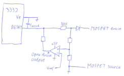
14. If desat triggers at 6v at Tj=120c, then we need a 4.2 zener to add to the 1.2V from the schotky diode.
15. If desat triggers at 7.5v at Tj=120c, then we need a 5.7V zener added to the 1.2V from the shotky.
16. The question now is where is the MOSFET current at these different zener diode settings. Zeners also only come in a limited number of voltages and they have Reverse break down with <240uA current so we need to make sure to check it's data sheet.
17. We know desat happens as low as 6v, so we'll use that as the spec since we don't want the desat to trigger at a lower than 150A. That meas we need to trigger a 4.2v with just 240uA. We'll go look at the ROHM KDZ series of 1W zeners since they have a graph showing breakdown voltage vs current.
18. Looking at http://rohmfs.rohm.com/en/products/databook/datasheet/discrete/diode/zener/kdz4.3b.pdf we go to the electrical characteristic curves. Here we look at the y axis and see where 240uA falls so we can find the correct zener voltage to order. 240uA is 0.24mA so we go to the 0.01 and then go up one line to 0.02. Looking across we can see if we choose a 4.3v diode only gets us about 2.8V, that's much too low. We'll look at our desired voltage on the X axis. We want 4.3v so we go up until we intersect the zener with the lowest rating at 240uA. Bad news, it looks like we have to use a 5.6v if we are going to use this diode model or we need to go look at other data sheets. We'll just go ahead and use the 5.6v for now until we can bench test it. At 240uA the 5.6v zener looks like it has a reverse break down at 4.5V, so this is the value we will be adding to our 1.2v shottky.
19. Desat pin voltage = 1.2v + Zener + Id * Rds_On so our desat at 6v detection is now 1.2v+4.5*4.14mOhm = 6.32V. 0.32 over our desat, but this can work to our favor since it's good to have the MOSFET have over current set lower as it's running hotter. Our 6v desat thresh hold is now reached at 74A, but remember this is with the MOSFET internals at 125c so it has less capability to handle high current.
20. If we look at the 25C numbers we see the desat triggers at 133A. On startup of a cold morning, our desat current is 175A before we panic and shut down in <5uS. That leaves us an additional 325A overhead until we reach our 500A threshold we determined to be the max current the MOSFET should see under ANY operating condition. Lot's of head room left.
21. Now since we designed for 6.0V desat, we need to check the currents at 7.5V, our other worst case number.
22. Keeping the 5.6v zener which is reversing at 4.5v, The 7.5V the -20c, 25c and +120c over amperage ratings are 1047A, 789A and 436A. These are some big numbers and they exceed our 500A limit for the MOSFET, so what do we do? We need to compromise and choose a higher desat voltage point. We look at the datasheet and we see 6.5V is the typical value. That means the manufacture knows the most common voltage is 6.5, but in some cases it could be 6.0 or 7.5v.

Designing for 6.5V we'll pick a zener reverse voltage using the above spec sheet method and go for 4.8v to reach the 150A limit with the MOSFET at Tj=120C.
-20c, 25c and 120c desat number then become 292a, 218A, 127A. Our worst case scenario numbers for the three temps are as follows

6.0V desat 1A, 1A, 1A <-- this would be painfully obvious during bench testing.
6.5v desat 292A, 218A, 127A
7.5v desat 873A, 656A and 364A <-- this would also be obvious during bench testing, desat would appear not to work

Even with a 1A to 873A variance, the MOSFET would more than likely survive due to it being a very short pulse and the MOSFET having a very high pulse current rating.

This is where a engineering decision needs to be made. How many of these are we building, 1, 10, 100, 10,000? Are we really going to be running at 175c Tj? I hope not, so that buys us more headroom if our application allows the flexibility. If we are only building a low qty such as 10-100 units, then it's going to be more cost effective to setup a simple bench test apparatus and check the desat function by hand with a scope and current sensor, then install the appropriate zener diode to tweak it if required.

Adding all of the extra circuit is over complicating it's function for little benefit. Lots of devices need to be tuned before being released to the public. What's your end goal?

The lower RDSon does make desat a larger challange, but always keep in mind the peak pulse rating of the device for desat purposes. It's capable of handling 1100A for up to 100uS and we only need it to last for <5uS. Less time = less destructive energy.

If you are just designing this additional circuit for the fun and challenge of it, then knock yourself out, but don't engineer something that isn't needed if it's a simple change that can be made during bench testing of the driver (you do plan to bench test and tune the driver don't you?).

This took a while to type out, but I have a project that will most likely use this driver anyways so I had to do this work at some point. I'm using a high RDSon MOSFET so I'm not going to have such giant current swings to worry about, but this was good practice for me anyways.

Another way to handle this situation might be to add a large 1mOhm-5mOhm shunt current sense resistor. This current sense resistor could also act as part of an over current protection circuit per MOSFET group in addition to lowering the range for Desat. What you can get away with depends on the desired power level.
 
As zombiess says, desat is a nice to have safety feature, but not a primary function. Useful for redundancy if the current sensor fails, and I suppose mostly used for IGBT-s where the supply voltage is several 100V. Not sure it is needed for a 6FET controller.

If you want to keep the current in the safe range, then measure and feedback the current directly. In my controller I use the cycle-by-cycle method described by dirty_d above, with a fast current sensor it shuts down the PWM within a few us. I use the comparator of the microcontroller, so only a few external components are needed and I can set the current threshold with the internal DAC. In this uC (Atmel ATXMEGA) the comparator is able to shut down the PWM output by hardware, so software action is not needed to limit the current (only configuring the modules), so there is no sw delay. This method can be the secondary current limit, the primary is the software current control loop.
 
the desat circuit is used to protect the drive from shoot-through event, when both adjacent mosfets are ON at the same time thus short-circuit the DC link capacitor to ground. the phase out current sensor would never see this current because it does not flow in that direction.

desat circuit should trip at 200% FLA. as junction temperature ggoes up, the threshold drops, but if it started at 200% you got some room to drop.
 
SjwNz, thought i would post my comments here rather than PM if you don't mind.

-the 0.1uF & 4.7uF caps need to swap position, 0.1uF needs to be closer to the ACPL333J.
-nice work on the ground stitching, that's a good idea.
-see if you can move your gate resistors closer to the mosfet.
-you should swap zener and MUR160 diode so that the diode's cathode is first to see the high voltage. at least then you are more free to bring ground plane into that area (though i agree, i would still be hesitant to put ground plane under the zener.
-after desat is a 1K and 100pF cap, move the 1K closer to the cap.
-this allows more of the trace to collect noise and THEN get filtered.
-it would be nice if you could re-position MUR160 & zener such that you can bring the ground plane closer to the mosfet gate pin. can one of these parts go on the other side of the board? can you move or tighten your special desat circuit to give you more room?
-definately you need cap after converter. low ESR type.
 
zombiess said:
11. Fun with ohms law. Our minimum desat votlage for and IRFP4468 at -20 degrees 1.725mOhm * 150A = 1.382V, a far cry from 6.5V.
zombiess, something is very wrong with your calculator!

1.725mOhm * 150A = 0.001725 * 150 = 0.25875V.

This is why we fiddle around with all that extra, because 250mV is a very low value to trigger the DESAT and how will you find a zener to tweak around such low voltage?
 
HighHopes said:
the desat circuit is used to protect the drive from shoot-through event, when both adjacent mosfets are ON at the same time thus short-circuit the DC link capacitor to ground. the phase out current sensor would never see this current because it does not flow in that direction.

I mean not the phase out current sensor, but the one (or a shunt) between GND and the low side FETs as dirty_d wrote, or between the high side FETs and +DC bus. This can be after the large DC cap and before the film cap, then its peak is the phase current or the shoot-through current, the average is battery current. But ok, it is another option, depends on the implementation if you put a sensor here or not.
 
I mucked something up somewhere trying to show the work (I've never been good at showing the work). I have a spreadsheet I created which does all the work for me. The final amp numbers are still correct.
It's silly to mess around with lots of extra parts on it when you can just tune it by hand. If you are going to produce lots of units in an automated process then it would make more sense.

If you are gong to add all that extra stuff to the built in feature, it would probably be better to just implement the entire through discrete components.

Yet another way to tackle the issue is using multiple parallel resistor of higher RDSon, such as the IRFP4568. Run the math on switching and diode losses vs the conduction losses then define your operating parameters. Will the controller be used more often >99% PWM duty or will it be used closer to 33% duty? Now look at the overall losses, what percentage of those losses are conduction due to the RDSon?

For dynamic inverters that don't see a high duty cycle the RDSon doesn't seem to play as large a role as the other losses. If you are building a steady state inverter with > 90% duty cycle, then the conduction losses appear to become more important. There are a lot of variables to account for when choosing a switching device.
 
zombiess said:
The final amp numbers are still correct.
I don't know about that, I haven't recalculated, but don't you see, even the DESAT variation over temperature is larger than the voltage drop across a MOSFET with such low RDSon.

Take my controller for example. 24-FET rated 200A. HighHopes found an IXYS MOSFET with RDSon of 6.4mΩ. 4 of them in parallel gives 1.6mΩ. Let the DESAT trigger at 400A: 0.0016Ω * 400A = 0.64V. This is not a very big voltage variation for the built-in DESAT to detect, with all those parameters varying from part-to-part and due to temperature.

You might be correct about how many controllers do we build, but with such tight tolerances, tests will have to be made, each gate driver chip will have to go through at least a few tests determining the DESAT threshold and current source accuracy, and this is over temperature. Also the zener and MOSFETs should really be tested. Quite a DIY challenge, for a few or even a single build. This will definitely keep some people from implementing a gate driver using DESAT detection. But perhaps a really thorough and easy to follow guide could make up for that.
 
Desat does not care about the number of MOSFETs in parallel. You only need to run the numbers for 1 MOSFET, then as you parallel them the over current point goes up. If you do the work for a single MOSFET with an over current at 200A, then add 3 more, your over current is now 600A. The system remains in balance. If how ever you wanted those 3 MOSFETs to over current at 200A THEN you would need to alter the zener on the desat. I myself had the same concern, but after you work the math you quickly see that the number in parallel doesn't effect it's operation.

Take a 10mOhm at 25c, dead short, 200A setting.

200A * 0.010 Ohm = 2V generated at the desat input. If it triggers at 6.5v, then you will need diodes that add up to 6.5=1.2-zener (if your Vf on the blocking diode is 1.2V, it could be different watch your datasheets and temps).

Some simple algebra and
6.5-1.2 = 5.3v zener

Now we put 3 of those same MOSFETs in parallel and want a desat current of 200A per MOSFET, but we have 3 of them so that's 600A
10mOhm RDSon / 3 = 3.333mOhm
600A * 0.003333 = 2v which means our 5.3v zener is still working just fine :)

This is why choosing a MOSFET with a higher RDSon could help you meet a design spec, lower RDSon isn't always better depending on the design needs. As you can see, if it's too low, it might make it more challenging to get the desat to operate if that feature is desired.

I've been working on math a lot more lately, unfortunately it's usually late at night and I make some goofs. I was looking at what I typed up last night and I'm not sure where I came up with that number, I need to go back and read through it to figure out where I zigged vs zagged.
 
200A per MOSFET is also pretty massive, not everyone has room for TO-247 devices. I know they are better thermally, but I just don't have the room. So I'll be running 50A per MOSFET max, so DESAT would be at 100A per MOSFET. And you are right, a controller like Lebowski's switches all the time, so RDSon becomes less important vs. switching performance.
 
6 step uinipolar pwm is often found in toys and low end controllers because it's easy to implement compared to SVM or FOC.

Back to desat. Futterama, what is the pulse rating of your specific MOSFET? They often have very high pulse ratings for <=60uS. That means if you stay under this spec and shut down in 5uS, the device should live. Is your amp rating in RMS amps or just peak amps? 50A peak is 35.35A, but 50A peak is 50A. The desat functions off the peak amps. If you are specing 50A RMS, then you need to calculate your desat as 50A * 1.414 * 200% = 141.4A. AC RMS = DC

Many on this forum are obsessed with low RDSon devices, but that's like looking at the world through a pair of powerful binoculars. You can only see the things you are looking at directly and your peripheral vision is no longer any use. RDSon needs to be taken in the context of the overall losses the MOSFET will experience.

Calculate MOSFET losses. Conduction + switching + diode and play around with them, it's very enlightenin seeing how duty cycle effects conduction and diode losses while switching stays the same.
 
The IXYS MOSFET that HighHopes suggested is this: IXTP180N10T

Pulse rating is 450A. It's not the one with the highest pulse rating I have found, but HighHopes is an IXYS fan, so according to him, it's better than a FDP032N08 with a pulse rating of 940A. It's IXYS vs. Fairchild you know :lol:
 
Futterama said:
The IXYS MOSFET that HighHopes suggested is this: IXTP180N10T

Pulse rating is 450A. It's not the one with the highest pulse rating I have found, but HighHopes is an IXYS fan, so according to him, it's better than a FDP032N08 with a pulse rating of 940A. It's IXYS vs. Fairchild you know :lol:

I confirm this, a few yrs ago we used IXYS and IRF MOSFETs at my job with similar current ratings, and the tested destructive limit was much higher with IXYS. They had large margin above the specified rating.
 
its true that bench testing to validate a specific desat circuit is probably beyond most DIY'ers. i think it would be better for ES to develop 3 "go to" designs. one for small power, focus on small. one for medium power and one for high power. then just tell users to NOT change the mosfet part number, NOT to change the gate resistor, NOT to change zener.. etc cause all those thing will be defined.

futureama, you should consider designing your board to be able to use desat circuit in the normal way OR your circuit so you can test if you even need your special circuit. if you don't need it, then simply do not populate, if you need it then good that its available.

peters, you're right if you put the sense resistor where you described it will catch the shoot-through current (you still need to guarantee it shuts down faulty drive in <10us). the problem with putting a sense resistor though is that you are really saying that the design is small power and usually lower performance.... but really cost effective and small volume of space. pros & cons.
 
Many on this forum are obsessed with low RDSon devices

Haha, thats me. but I started thinking about using a higher RDSon fet while playing with my little Desat circuit
so it wouldn't be so touchy with changes in temperature . And like you said, most of the heat comes from the switching so having super low RDSon
may not matter so much but If you have a controller with no desat then I say its fine to use low RDSon. I properly don't need to have desat but
I learnt about it and want to use it and more reasons to play with my new scope too :D

Peters , I was thinking about putting currents sensors in line with the Fets before I spent a month reading a number of the threads on ES, but turned away from that method as I don't think its suitable once the power starts getting higher. At this stage I am only making a 2kw controller but I want to use what I have learnt from this design and use a similar design for maybe a 5 to 10kw controller. I will give the cycle by cycle current limiting a go as I have heard of it before , but in the my first controller, when I detected a high current I would very quickly decrement the PWM duty register , and when the current dropped enough, I would then slowing increment the PWM duty register again until it matched the throttle setting Or the current limit triggered again.

Thanks for looking over the PCB Highhopes , I and pretty sure I understand all the changes to suggested
I made my little PCB after work today and will start to assemble it tonight. Will use it to test the desat circuit I did and will then disable my little addon and test
the 333J destart threshold level with the IRFP4468 mosfet and see how much current it takes before it blows it up.
 
Back
Top