Worlds Worst Dyno !

adrian_sm

1 MW
Joined
Feb 22, 2009
Messages
2,429
Location
Melbourne, Australia
Okay, here is my submission for "Worlds Worst Dyno". :lol:


Worlds_Worst_Dyno_v1.jpg

Mechanical Setup is:
- two angle brackets and a bit of scrap wood to mount the motors
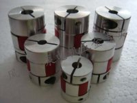
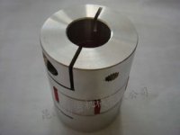
- a small section of pressure hose and hose clamps to couple the motors

Electical Drive setup:
- left motor is the motor under test (C6364-230kv)
- right motor is the load (C8085-250kv)
- left controller is currently a Turnigy 85A ESC with a servo tester to control speed
- right controller is a Xiechang 6 fet, with regen capability, to supply the load

Measurement:
- no torque sensing
- RPM sensing via oscilloscope across two phase wire
- Cycle analyst for one motor
- Watt Meter for the other (note: watt meter and CA current reading don't match )
- IR thermometer for motor temps
- LiPo buzzer to make sure I don't kill the batteries
 
So this set-up has so far let me:
1) test the efficiency of two controllers, EB306 (Xiechang/Keywin) vs Turnigy 85A
2) see the change in no load power as motors warm up
3) test motor temp rises for different loads. Two loads were just BEMF (~200w) and BEMF + regen (~700w) of driven motor
4) see rough #'s for the inefficiency of regen


What next:
1) Motor temperature soak test
- monitor motor temperature of the drive and driven motors for a "constant" load
- wait for temperature to stabilise
- first load is just the back emf of the driven motor
- second load is with regen enabled on the driven motor
- run it at full throttle, with charger topping up battery to hopefully stabilise voltages for the test
- possibly repeat at less than full throttle
- repeat with a range of motors

2) Better RPM measurement
- measuring the phase voltages of the driven motor makes for easy frequency measurement, but
- the choppy phase voltages from regen makes using the oscilloscopes to measure the motor speed a hassle

3) Torque sensor
- not really a dyno unless you can measure the actual torque
- first idea is to mount the drive motor shaft rigidly to the driven motor shaft via a metal collar (motor out of balance will probably stop this from working nicely)
- then react the drive torque with a lever arm to a load cell
- hook this up to an arduino, along with the RPM and log straight to SD or PC via USB
 
The setup looks interesting. But for someone who's not familiar with Dyno stuff, I have no idea how it works. I see two motors connected with what looks like a rubber hose.

Can you explain how this thing works? In layman terms if possible. Thanks.
 
How does it work?

Simple really. When you turn a BLDC motor it resists being turned. If you hook it up to a controller, and enable regen, it resists even more. So you can use this as a load for another motor to drive against. For more detail than that try looking at this on back EMF and this on alternators

The downside of this method of creating a load is that I can't vary the magnitude of the load with any resolution. The controller on the driven motor is pretty dumb out of the box, and does not have variable regen.

For me I just needed some rough test equipment to be able to watch how quickly different motors temperatures rise for the same load condition. And get some rough feel of the efficiency from that. I had all the motors, controllers etc already, so it only cost me $10 for a couple of brackets, hose and clamps. Money well spent I say.
 
t3sla said:
one word.

video!

By special request. Here she is in all her refined glory.
Cycle Analyst is displaying the drive motor stats.
Watt Meter the drive motor regen stats.

Test Motor: C6364-230kv
Load Motor: C8085-250kv
Simple BEMF load
[youtube]NFLzu_g98oM[/youtube]


Test Motor: C6364-230kv
Load Motor: C8085-250kv
Regen On
[youtube]I_T461NHCDw[/youtube]

Notes:
Drive motor heats up quicker than the load motor, which is good for my purposes, as the load motor is not the limitting factor
The regen controller is keeping pretty cool so far too. Might have something to do with the nice 2mOhm IRFB3006 FETs I built it with.
 
That looks like a useful bit of kit 8)

Do you have hall signals from the generator going to the Xiechang , or does it regenerate without them ?
 
It is rough as guts, but will be good enough for some basic test I want to do.

No Halls. Motor does not have them, and the controller is one with the sensorless circuit so works without them.

BTW. Any tips on what hall sensor to use if I want to add them. (Part# would be awesome) I have never needed to add them to a motor before, so never looked at what is needed.
 
Just realised I have a box of $1 throttles. Might see if I can use the hall sensor from one of those to do my RPM sensing via the driven motors leaking flux.

[EDIT] It works a treat. Connected it up to the throttle connection, but pulled out the signal wire at the connector so that it powers up and I can attach the osciloscope to it. Then held the hall sensor near the motor can.

Nice Clean Siganl. Woo hoo.

 
A variable load can be created at around the cost of a normal ebike-controller.

Remove the regen controller and replace it with a three-phase rectifier (find some surplus cheaply at ebay). Make sure the rectifier is rated for ~800 Hz duty. 50 & 60 Hz rectifiers work, but heat up substantially. Plug a boost circuit inbetween the rectifier and the battery - and so you can controll load at all rpm's.
 
@ the stork. Cool. So the boost circuit is how you get the adjustment? I am an electronics idiot, so any guidance on what to buy/build? Otherwise I was going to try and hack the ebike controller for variable regen since it is already on my bench and rectifying and bucking the voltage up.

@full-throttle. Generous of you mate. Have you got it setup with amplifier etc, or would I need to sort that out. I have had this load cell one my eBay watch list for about a year. What do you think?

LOAD CELL 10kg/22lb NEW - Precision Low Cost

http://bit.ly/Wfzk9E

What I am struggling with is the best way to couple the motors. Without access to a lathe I can't make the coaxial rigid coupling I have in mind. Which is basically a short rod with 12mm hole one end, and a 10mm or 8mm hole the other. The a couple of grub screws I guess to take the torque. Hmmmmmm
 
adrian_sm said:
@ the stork. Cool. So the boost circuit is how you get the adjustment? I am an electronics idiot, so any guidance on what to buy/build? Otherwise I was going to try and hack the ebike controller for variable regen since it is already on my bench and rectifying and bucking the voltage up.

Hmm, the problem is getting the energy back into the pack. This is why the boost part is there (you need to get over the battery pack threshold before it will conduct). As I previously stated; get a three phase rectifier. Look into 'PFC' controller chips/application notes. You will need to figure out the boost circuit on your own. You've already built this system, with some research - you'll manage this too ;) This will be very efficient compared to the regen from a normal controller.
 
full-throttle said:
It's the same (or similar) load cell, already hooked up to the ADS1232
All you will need is a micro (arduino will do) to talk to the ADC, there should be code for arduino written already.

Sounds perfect.

While you are feeling charitable, any chance of getting my hands on one of those power supplies I hassled you for a while back? Would be good to crank up the current on my RC chargers.
 
Teh Stork said:
Look into 'PFC' controller chips/application notes. You will need to figure out the boost circuit on your own. You've already built this system, with some research - you'll manage this too ;) This will be very efficient compared to the regen from a normal controller.

Love the idea of variable load, especially if I had it as a part of a closed loop control. But too much hassle for now for the "World's Worst Dyno". I just don't have the time to learn what I would need to learn to make it work, and not blow myself up in the process.

But thanks for the encouragement. :D
 
adrian_sm said:
Sounds perfect
I'll email you when I get home. Forgot all about the PS.. :oops:
re: variable load - you could prob do it by changing R12 with a pot while in regen mode :idea: Just got to be careful not to go over the voltage limits.
 
Great.

Yes to the R12 mod. Just haven't studied the schematic.
 
adrian_sm said:
What I am struggling with is the best way to couple the motors. Without access to a lathe I can't make the coaxial rigid coupling I have in mind. Which is basically a short rod with 12mm hole one end, and a 10mm or 8mm hole the other. The a couple of grub screws I guess to take the torque. Hmmmmmm

I used one of these on my weedwacker and it's holding up quite well. They are relatively cheap on ebay and they have a 12mm X 10mm.


http://www.ebay.com/itm/BF-10mm-X-12mm-CNC-Flexible-Plum-Coupling-Shaft-Coupler-D25L30-/251146977151?pt=LH_DefaultDomain_0&hash=item3a7986bf7f
http://www.ebay.com/itm/CNC-10x12mm-Motor-Shaft-Coupler-10mm-to-12mm-Flexible-Couplings-OD-26x35mm-/150928337295?pt=LH_DefaultDomain_0&hash=item232407a98f
http://www.ebay.com/itm/Tight-Flexible-Shaft-10-mm-x-12-mm-CNC-Stepper-Motor-Coupling-Coupler-D-25-L-30-/261092442562?pt=LH_DefaultDomain_0&hash=item3cca5281c2
 

Attachments

  • coupling.JPG
    coupling.JPG
    13 KB · Views: 4,281
  • coupling1.JPG
    coupling1.JPG
    7.5 KB · Views: 4,281
Nice. Would be much prettier than my piece of tube and clamps.

Unfortunately I actually need the same thing but not flexible. The plan is to mount the drive motor directly on the driven motors shaft, and get rid of the bracket I currently use to mount the drive motor. Then to stop the drive motor spinning, use a lever arm resting on the load cell, that bolts onto the stator end..

I could possibly hack this one to be rigid enough, but seems really daft to try and put back all the material they spent so much time and effort to remove in making these.
nEO_IMG_A263A(3).jpg
 
Back
Top