Worlds Worst Dyno - Version 2

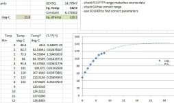
Repeated the 8kHz run from ambient, with identical predicted equilibrium temperature of 81 deg-C above ambient.

2013-02-11 - YEP150A - 8kHz PWM - 50% speed temp rise data.JPG

Then let the motor cool to ~50 deg-C before doing the 16 kHz run, and again temp rise was way way faster. With an even higher predicted equilibrium temperature of 120 deg-C above ambient. But I called the test off a bit early as windings were already getting up to ~149deg-C.
2013-02-11 - YEP150A - 16kHz PWM - 50% speed temp rise data.JPG

Notes:
- Speeds were approx 5% lower than last test, and torque about 5% higher. (~1.37Nm)
- 8 kHz predicted ESC equilibrium temp was +51 deg-C above ambient
- 16 kHz predicted ESC equilibrium temp was +79 deg-C above ambient
- timing on the ESC is currently at 0-deg (with options of 0,6,12,18,24,30)

Summary:
- 8kHz is better than 16kHz for ESC and motor temperatures with existing setup.
 
Treid 8 kHz, 12 deg timing. Same speed, same load.
- Motor equilibrium temp was unchanged.
- ESC equilibrium temp was down a few degrees, but really in the noise of the experiment data accuracy.

Tried 16 kHz, 12 deg timing. Same speed, same load.
- Motor equilibrium temp was way down, now at ~85 deg-C above ambient (down from > +100 deg-C above ambient)
- ESC equlibrium temp was, +59 deg-C above ambient. (down from +79 deg-C for 0-deg timing)

Summary:
- too low timing significantly adversely affected both the motor and ESC waste heat at higher PWM frequency
- higher PWM frequency still appears to result in higher motor (~5-10 deg-C) and ESC (~20 deg-C) temperatures .
- ESC had more trouble starting against the dyno load from stand still at 12 deg timing, compared to 0 deg timing.
- higher ESC temp coincides with high motor temp, for cases where timing does not appear to be advanced enough, when comparing similar runs with different temperature rises.

Here is a screen dump of the summary data.
Note:
  • Eq Temp* = Predicited thermal equilibrium temperature
    dTemp = temperature above ambient
    Fin.T = final motor temperature before test halted (note equilibrium temperature are extrapolated beyond this to predict equilibrium)
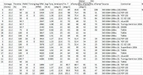
2012-02-11 - ESC & Motor Equilibrium Data.JPG

Highlights:
- synchronous rectification really helps ESC temps at partial throttle
- YEP 150 performed thermally better than an EB306 at partial throttle, even with essentailly no heat sink, verses the ebike controllers huge aluminium case
- full throttle temps are not an issue for any of the controllers

And here is the text of the data:
Code:
Voltage	Throttle	PWM	Timing	Avg RPM	Avg Torq.	Ambient	Fin. T	dTemp1	Eq. dTemp*	Eq. dTemp*	Source	Controller
[Volts]	[%]	kHz		[RPM]	[N.m]	[deg-C]	[deg-C]		[deg-C]			
22.2	50	?		1130	1.1	23.2	69	45.8	55	108	SK3 6364-190kv (10)	CON61
22.2	50	16	0	1919	1.33	22.6	98	75.4	95	51	SK3 6364-190kv (11)	YEP 150
22.2	50	8	0	1931	1.36	22.6	98	75.4	81	40	SK3 6364-190kv (9)	YEP 150
22.2	50	8		1966	1.41	22.6	92	69.4	79	84	SK3 6364-190kv (8)	CC ICE 100
22.2	50	?		2047	1.09	22	70	48	52	71	SK3 6364-190kv (7)	dLux100
22.2	50	?		2082	1.08	22	80	58	60	74	SK3 6364-190kv (5)	Turnigy Sentilon 100A
22.2	50	?		2140	0.91	22	60	38	42	50	SK3 6364-190kv (6)	EB306
22.2	75	8		3047	0.99	25	63	38	44	69	SK3 6364-190kv	Tz85A
22.2	100	8		3817	1.01	23	65	42	44		SK3 6364-190kv	Tz85A
22.2	100	8		3883	1.31	24	69	45	49		SK3 6364-190kv	Tz85A
22.2	100	16	0	3913	1.27	22.6	74	51.4	54	19	SK3 6364-190kv (11)	YEP 150
22.2	100	8	0	3915	1.23	22.6	75	52.4	54	20	SK3 6364-190kv (9)	YEP 150
22.2	100	8		3978	1.27	22.6	75	52.4	54	25	SK3 6364-190kv (8)	CC ICE 100
22.2	100	?		4020	1.04	24	63	39	41	36	SK3 6364-190kv (4)	SuperBrain 100A
22.2	100	16		4020	1.02	24	64	40	41	29	SK3 6364-190kv (2)	Tz85A
22.2	100	8		4020	0.99	24	64	40	42	29	SK3 6364-190kv	Tz85A
22.2	100	?		4027	0.99	20	59	39	40	21	SK3 6364-190kv (7)	dLux100
22.2	100	?		4266	0.985	22	64	42	43	23	SK3 6364-190kv (5)	Turnigy Sentilon 100A
22.2	50	16				24		-24			SK3 6364-190kv (2)	Tz85A
22.2	50	8	0	1899	1.37	22	90.7	68.7	81	51	SK3 6364-190kv (9)	YEP 150
22.2	50	16	0	1826	1.37	22.6	115	92.4	120	79	SK3 6364-190kv (11)	YEP 150
22.2	50	8	12	1869	1.45	22.8	99.6	76.8	81	47	SK3 6364-190kv (12)	YEP 150
22.2	50	16	12	1869	1.45	23.8	101.1	77.3	85	60	SK3 6364-190kv (13)	YEP 150
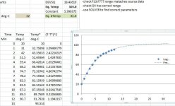
 
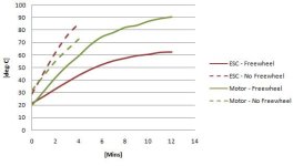
Effect of synchronous rectification @ partial throttle

Here is a quick plot of the same motor, ESC, speed, load, settings, etc., except I switch the "active free-wheeling" / synchronous rectification on and off. Start temperatures were a bit different but you get the idea.

As you can see a massive difference in ESC heat. Not sure about the motor heat, due to cutting the test short as I didn't want to fry the ESC, but looked about the same to me.
2013-02-11 - Effect of synchronous rectification on motor and ESC heat.JPG
 
adrian_sm said:
There aren't a lot of commercially available sensor-less sine commutation controllers unfortunately. I might be able to get my hands on one of the LSDZS ones for a brief period, but I want to make sure I make the most of the testing before I grab it.
BTW I blew up the only sensorless LSDZS I had left. I'd say it's beyond repair :oops: I can get another one or tell you who's got them in Melbourne. These are 6-fet ones and they are tiny, size of a RC ESC. The same person gave me an Ananda sensorless that works very well also, the startup is smoother. Crystalyte make a sensorless controller too and you know who's got them.
 
Is that the one you had on your commuter? All the cheap small 6fets I have tested have been pretty average either not handling the high RPM, or sucking at partial throttle. And although small, not in the realm of the RC ESCs.

Got links to the model of the controllers you are talking about?

I have had an offer from a mutual acquaintance to lend me the LSDZS sine wave sensor-less model I linked to above. The supplier told me it would not suit my needs, but I am still keen to test it.
 
I'd like to see if the sine-wave in the link is any good. I'm pretty sure we were talking about the same person BTW.
Speaking of sine-wave, did you know the Adaptto Logic runs in sensorless mode? Unfortunately it doesn't run in sine-wave sensorless, only PWM. You are welcome to try it too.

Yes, the 12-fet was on my commuter for a while. I also modified one to run on my ex Stealth Bomber @ 70A. Believe it's still going. The one I blew up was due to a shorted wiring inside a motor while testing.
I have not tested the micro 6-fet yet.
 
adrian_sm said:
Effect of synchronous rectification @ partial throttle

Here is a quick plot of the same motor, ESC, speed, load, settings, etc., except I switch the "active free-wheeling" / synchronous rectification on and off. Start temperatures were a bit different but you get the idea.

As you can see a massive difference in ESC heat. Not sure about the motor heat, due to cutting the test short as I didn't want to fry the ESC, but looked about the same to me.

I'd expect the motor heating to be the same or even slightly less without the synchronous rectification.

You're generating some great real-world data there. I'm especially interested in how the timing affects efficiency and how things behave at partial throttle.

I was surprised at how much difference there was between 8khz and 16khz switching speed.

Graphical representations of the results are awesome.

Everybody can learn a lot from your work.
 
full-throttle said:
I'd like to see if the sine-wave in the link is any good. I'm pretty sure we were talking about the same person BTW.
Speaking of sine-wave, did you know the Adaptto Logic runs in sensorless mode? Unfortunately it doesn't run in sine-wave sensorless, only PWM. You are welcome to try it too.

Yes, the 12-fet was on my commuter for a while. I also modified one to run on my ex Stealth Bomber @ 70A. Believe it's still going. The one I blew up was due to a shorted wiring inside a motor while testing.
I have not tested the micro 6-fet yet.

As for the 6fet LSDZs I am really not interested in any other sensor-less controllers unless they have synchronous rectification based on the findings above. The Adaptto Logic is too expensive for my application.

But definitely interested in the sine wave sensor-less controllers. I keep getting conflicting impression of how much it helps suppress noise from the videos I have seen.
 
fechter said:
I'm especially interested in how the timing affects efficiency and how things behave at partial throttle.

I couldn't pick any difference in efficiency for the 8kHz 50% runs between 0 & 16deg, both around the 77-80% system efficiency. But my kitchen scale method of measuring reaction torque probably has about 1-2% of variation. So I will need to be a bit more careful in how I zero my scales if I want to get a good picture of efficiency differences, as I would only expect a few percent difference.
 
Miles said:
Thanks for the re-test Adrian. Interesting... I haven't a clue why using the higher frequency has such a negative effect......

What are your thoughts on jag's theory?

jag said:
I'm certainly no expert in the design and analysis of electromagnetic machinery. However it seems to me that significant hysteresis and eddy current losses are caused whenever there is rapid change in magnetic field strength, independent of if commutation or PWM is the source. Commutation causes large magnitude changes, but of a moderate frequency. PWM causes small magnitude changes, but with much higher frequency. (Some scope shots i saw on ES years ago suggests current ripple is maybe 10% of mean current, but that may have been a hub motor.)

I don't believe you need a full inflection of magnetic field to do the usual hysteresis loop. So maybe the high frequency current ripple is enough to see some hysteresis losses...
 
Hysteresis Losses

Relevant ES post: http://www.endless-sphere.com/forums/viewtopic.php?f=30&t=16376&p=540597&hilit=bldc+theory#p547362
And a nice White Paper linked to: http://www.ep2000.com/Templates/white%20papers/MagneticDipolesEP.pdf
Typical hysteresis curve:
file.php


Interesting and potentially relevant quote from the paper p.7.
High Frequency Hysteresis Losses.PNG

Now my brain is only absorbing half of this at the moment, but here goes:
- the high frequency PWM switching creates current ripple according to the applied voltage less the BEMF, and inductance.
- this causes little hysteresis loops that although small in area, add up due to the high frequency.

But even if this is true, it still surprised me that a higher PWM frequency means more heat. I would have thought twice the frequency, means slightly more than half the current ripple, due to inductance. So delta-H on the curve would be a bit over half. Meaning delta-B (flux density) on the curve would be less than half. So the area would be less than a quarter, but at twice the frequency. Resulting in very roughly half the heat. Still doesn't match the experimental results. I am missing something.....

What about eddy current losses? If we are getting current ripple due to the PWM chopping, then the flux density is also changing. Therefore there has to be eddy current losses right, that are proportional to the freq squared, and flux density squared. Now the change in B at a higher frequency will be small due to the flatness of the BH curve when first reversing directions, so shouldn't change much. So it will not offset the event happening twice as often. This might explain when a higher PWM frequency may have more losses....

Man. Too late and not enough caffeine in my system to think this through properly. I have no idea of the magnitude of these effects, and am just looking for anything that correlates....
 
Okay starting to find some relevant research.

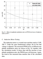
Title: Modeling of Eddy-Current Loss of Electrical Machines and Transformers Operated by Pulsewidth-Modulated Inverters
http://www-personal.engin.umd.umich.edu/~chrismi/publications/2008_44_8_IEEE_TMAG_Iorn_loss.pdf

Effect of modulation ratio on Losses in an induction motor.PNG
 
Title: Comparison of the Iron Loss of a Flux-Reversal Machine Under Four Different PWM Modes
Ref: https://www.google.com.au/url?sa=t&rct=j&q=&esrc=s&source=web&cd=12&cad=rja&ved=0CDgQFjABOAo&url=http%3A%2F%2Fecl.hanyang.ac.kr%2F%3Fmodule%3Dfile%26act%3DprocFileDownload%26file_srl%3D1172%26sid%3D2046055d80906c49b0e5824d6bbc4c18&ei=TN4YUcBno6uIB4aQgLAE&usg=AFQjCNHr9KS8ex7-HD0gZiL7DOPUz58Lhg&sig2=POe6roOI4uwJ17w8Q2cm3Q&bvm=bv.42080656,d.aGc

2) Computation of the Hysteresis Loss: When a magnetic
field with time harmonics is induced to the iron, the hysteresis
loss is increased because minor loop happens additionally. In
order to calculate an accurate hysteresis loss, therefore, both
major loops and minor loops must to be considered
 
I run a quick sim of the 6 step model with synchronous rectification at 8Khz and 16Khz, no advance, ~50% BEMF, ~25A phase (1.3n.m with 190kv), 40uH inductance approximated from my 6374 (14T). Unfortunately, it only confirms that while the frequency doubles, the ripple is half.

Anyway, I don't think hysteresis losses, even if made worse by frequency ripple increase, would be able to cause the amount motor heat required to explain the difference you are seeing, copper losses is a more likely candidate. I would suspect the controller timing control to potentially being a bit late when running at 16kHz and causing your motor efficiency to drop. You should be able to confirm this by looking a the phase voltage in both cases.

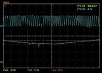
8k_16k_zps4195a8cc.jpg


With 40uH you may need higher then 20khz to start seeing benefits from the higher frequency...

I mean if there is to much torque ripple with 16khz and 8khz maybe 32 or even 24 would be the next place to test? If there is a dead time with the PWM where the current can fall to 0 in between and it does this with 8 and 16 khz it might not show the benefits. I watched the current with my chip from lebowski at 20khz 30khz and 40khz and its really cool how it steps up a bit as the pwm is on but then stays at that current amount even when the fet is off then goes higher when the next on pulse arrives.

What algorithm are you using?
 

Attachments

  • 42 amps on low side 66v.JPG
    42 amps on low side 66v.JPG
    61.6 KB · Views: 1,268
@walls99. Thanks for running the simulations. Unfortunately no surprise explanations. What are you using to simulate it? What is the simulation software actually capable of modelling? I have done a lot of FEA work over the years, and realise that simulations can be misleading if you are not aware that they do not model reality, they only model what you tell them to model.

I tend to agree that hysteresis losses are unlikely to be of a big enough magnitude to explain the amount of waste heat, but that is more based on gut feel than actual estimation.
When you talk of copper losses, are you just talking about resistive losses? Then I can't see this explaining the significantly higher waste heat for the same average current.
Or are you talking about eddie current losses? Which I know less about.

As for Timing @ 16kHz. Yeah that was pretty obvious with the reduced heat when I advanced things. But why? I thought the advance would be more to do with the load, than the PWM frequency, unless the processing lag had something to do with it.

@Arlo1.
- FYI The controllers I am exploring all are limitted to 8-16kHz PWM.
- From walls99 simulations the current ripple is only +/- 4Amps on average of 25Amps so not big enough to cross zero during the flat top of the 6 step, but does elsewhere.
- What is your plot off? Green = gate switching? Yellow = phase voltage?
 
adrian_sm said:
@walls99.
- What is your plot off? Green = gate switching? Yellow = phase voltage?
Yes green lol IM color-blind and Yellow = Phase amps It shows how when the PWM on time increases the amps just a bit at a time but not letting them fall to far so the current ripple is not to bad.
 
adrian_sm said:
What are you using to simulate it? What is the simulation software actually capable of modelling?
It's a simple LTspice motor model (R+L+BEMF) initially made by Bearing to simulate a 6 step RC controller that I modified to simulate various PWM scheme and the zero crossing detection logic in order to confirm the observation I was making while developing my controller. It does correlate quite well with what I could measure.

adrian_sm said:
When you talk of copper losses, are you just talking about resistive losses? Then I can't see this explaining the significantly higher waste heat for the same average current.
Yes, resistive losses and I would expect you have higher battery and phase current. If you have the same output torque and speed with a fixed battery voltage in both experiments, then you can't have the same average current. The waste heat is taking power away that would cause output torque or speed decrease if you had kept the same input power/current.

adrian_sm said:
As for Timing @ 16kHz. Yeah that was pretty obvious with the reduced heat when I advanced things. But why? I thought the advance would be more to do with the load, than the PWM frequency, unless the processing lag had something to do with it.
The advance calculation is the tricky part to work out with the sensorless 6 step method, I found it varied mostly with the commutation speed and the phase current but PWM frequency and processing time also need to be compensated for at higher RPM. My guess is that something is not quite right in the controller software at 16kHz. For example, negative timing advance (retard) could cause the loss of efficiency you see because the commutations is late vs the BEMF and the phase current generates less torque than when timed correctly. So you need more current to ouput the same torque as before -> more copper losses...
 
walls99 said:
adrian_sm said:
When you talk of copper losses, are you just talking about resistive losses? Then I can't see this explaining the significantly higher waste heat for the same average current.
Yes, resistive losses and I would expect you have higher battery and phase current. If you have the same output torque and speed with a fixed battery voltage in both experiments, then you can't have the same average current. The waste heat is taking power away that would cause output torque or speed decrease if you had kept the same input power/current.
I guess I was referring to similar average phase current/torque not input current.

Reviewing the data now it looks like the big temperature difference was due to the issue regarding timing at 16kHz.
Here is some data from 50% throttle runs with the YEP controller @ 22.2V ~1830 rpm.
Code:
Th%  PWM   Timing   N.m   Motor dTemp   ESC dTemp
50    8    0        1.37   +81           +51
50    16   0        1.37   +120          +79
50    8    12       1.45   +81           +47
50    16   12       1.45   +85           +60

When I drop the voltage down to 16.4 V, and have throttle at ~70% to match speed I get
Code:
Th% PWM   Timing   N.m   Motor dTemp   ESC dTemp
70   8    0        1.29   +60            +23

The at different throttle % & speeds still at 16.4V
Code:
Th% PWM   Timing   N.m   Motor dTemp   ESC dTemp
100   8    0       1.27   +52            +22
50    9    0       1.29   +71            +40

Updated Summary:
- major heat losses at higher PWM seen earlier can be attributed to incompatible timing
- higher PWM still causes more heat but only in the order of +5% in the motor, and +30% in the ESC
- same torque at same speed at a 70% lower voltage, makes for a cooler motor by -30%
- same torque at half full throttle speed can increase motor temperature by 40-50%
 
I am still trying to convince myself of what is happening.

Higher PWM should mean lower hysteresis losses (smaller area twice as often), but higher eddy current losses ((flux_density*freq)^2)

So based on the test data for my set-up the eddy current losses are dominating? So the only remidies are:
- low PWM frequency (which goes against the previous conventional wisdom)
- different motor: thinner laminations
- gear the system down, via voltage or kv
 
Maybe I should tackle this a different way. From the outcome that I am seeking....

I want to define the system components for my friction drive, including ESC, motor and battery voltage. Optimising it to minimise waste heat across the full range of load speeds. This is most critical when bogged down going up hills.

The YEP ESC has proven the best performer out of all the ESC tested boht RC and ebike style. With the lowest temperatures at full and partial throttle. Likely due to the synchronous rectification, and low fet RdsOn.

Next up, the data above says loud and clear do not gear the system too high. So I need to decided on the maximum assist speed, then pick kV and battery voltage. For EU EN15194 style bikes this would mean ~32-35kph max to give good assist right up to 27kph ish , for US 750w/AU 200w ~45kph based on what feels right on the road, but this may have to be modified down depending on the long hill type tests.

The interesting question in my head is: does compensating with voltage for a different kV motor have any impact on waste heat across the full speed range. Pity I don't have two motor of the same size in different KVs. Closest is a SK36364-190 vs SK36374-168.

Guess I'll test these and see what I see....
 
adrian_sm said:
I am still trying to convince myself of what is happening.

Higher PWM should mean lower hysteresis losses (smaller area twice as often), but higher eddy current losses ((flux_density*freq)^2)

So based on the test data for my set-up the eddy current losses are dominating? So the only remidies are:
- low PWM frequency (which goes against the previous conventional wisdom)
- different motor: thinner laminations
- gear the system down, via voltage or kv
I dont think PWM frequency changes eddy current losses.
But with higher PWM you do get more switching losses.
 
@Arlo1, But I am definitely seeing more heat in the motor at higher PWM frequency.

[EDIT] actually I should run more tests before I am sure.....
 
Back
Top