You are using an out of date browser. It may not display this or other websites correctly.
You should upgrade or use an alternative browser.
You should upgrade or use an alternative browser.
Worlds Worst Dyno - Version 2
- Thread starter adrian_sm
- Start date
adrian_sm
1 MW
Miles said:Good sleuthing, Adrian. How about us simplifying/adapting this version to better suit our needs?
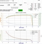
Here is a modified version of the excel DriveCalc, hacked towards some of my needs.
Modifications List:
- - Added basic SK3 6364-180kv motor to "Motors" sheet
- Added new rpm and speed based graphs to "Calculator" sheet
- Added battery current limit entry on "Calculator" sheet
- Added new table of calculations for battery current limit on "Auswertung" sheet, used ebikes.ca old simulator model for calculating motor currents. Ref: http://ebikes.ca/simulator/
- Changed minimum RPM to 50Hz on "Auswertung" sheet, cell E11. Old furmula is in notes for this cell
- Increased # data points for graphs. Hope it didn't break anything
- Moved Graphs around on "Calculation" sheet
Notes:
- - Speeds are currently calculated for a friction drive setup, using the diameter entered in the motor sheet for the "wheel" diameter.
- For direct drive hubs just enter the wheel diameter
adrian_sm
1 MW
Now if I could just build an equally dodgy model of the controller losses, I could virtually tackle the more imminent issues for me.
Anyone got a copy of an excel file that calculates the various switching, diode, resistive losses etc in an ESC? Something like this one bigmoose posted a screen grab of.

I followed the references but this points to a fairly complex model that is above my head.
Anyone got a copy of an excel file that calculates the various switching, diode, resistive losses etc in an ESC? Something like this one bigmoose posted a screen grab of.
I followed the references but this points to a fairly complex model that is above my head.
Nice work! Thanks for taking the bait! LOLadrian_sm said:Miles said:Good sleuthing, Adrian. How about us simplifying/adapting this version to better suit our needs?
Damn you ! :lol:
adrian_sm
1 MW
I don't think I have got a chance of calculating the FET losses for some random controller, as I wont know:
- the charge current, and therefore switching times to calcuate the switching losses
- or the dead time between phase switching to avoid shot through, that dictates the diode losses
So back to real world testing for me. :lol:
But it did teach me the very basic premise that double the switching frequency doubles the swithcing losses. I was just wondering if with these low resisance/inductance motors if the fat rise tims result in high currents during the switching due to longer switch cycle times. This could result in a high current during the switching phase. And since all the switching losses are pretty much proportional to the current squared, this may result in more waste heat.
Or does average current not change enough to make any difference? Any knowledgeable people out there feel like educating me before I waste more time on wild goose chases?
adrian_sm
1 MW
Effects of Partial Throttle on Controller Temperatures
Okay ran a few tests to see the effect of partial throttle on controller temperatures. With some interesting results.
The test setup was
Powersupply = 22.2V
Drive motor: SK3 6364-190kv
Load Motor: C8085-250kv
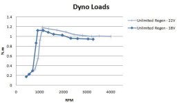
Load Regen Controller: EB306 EBS Level = Unlimited, giving approximately 1N.m of load.
Here is a graph of the regen load for reference. Note torque is relatively flat, so phase currents and motor heat will be fairly constant, but overall power levels will drop as speed drops.

Then I ran various controllers through a similar test.
1) First full speed, 100% throttle
- this is to get the ESC, motors etc all up to normal operating temperature
2) Reduce the drive motor throttle until speed just starts to drop
- this introduces switching losses into the controller
3) Reduce the drive motor throttle until the motor speed is roughly half the full speed from (1)
- typically this results in slightly higher torque by ~10%, due to the nature of the regen
- and we will get significant switching and diode losses etc.
All the controller went through this test except for the EB306 ebike controller, as it could not run the motor cleanly at full throttle, so it just did the 50% throttle test.
The list of controllers tesed so far are:
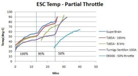
Summary:
- at 100% throttle all controllers are looking fine
- at 95% throttle all controllers start seeing significantly more waste heat
- at 50% throttle all controllers got uncomfortably hot, with many tripping internal temperature limits
- typically the larger the controller and the bigger the heatsink, the cooler they were
- the ebike style controller handled the partial throttle load the best, possibly because it is design to operate with significant PWMing of the phase current, or possible as it is just significantly larger with more thermal mass, and more surface area to shed the heat.
- On bike tests have seen much lower ESC temperatures. Possibly reasons are more air flow & lower duty cycle.
- On the bike it is more typical to be:
---- full throttle on the flat, with minimal controller PWMing
---- going up a hill for a bit with significant current limitting kicking in causing all the ESC heat, followed by going down hill with either 0 or 100% throttle that gives the ESC a rest.
---- waiting at lights or just pedalling
Conclusions:
- on bike tests to date I ahve done appear to have been very easy on the controller, given the much lower temperatures I have seen
- all of the RC ESCs to date have not performed well on a continuous partial throttle with a decent load
- if I can get a controller to work on the bench for the continuous motor loads I am interested in, then the controller should be fine out on the road.
Okay ran a few tests to see the effect of partial throttle on controller temperatures. With some interesting results.
The test setup was
Powersupply = 22.2V
Drive motor: SK3 6364-190kv
Load Motor: C8085-250kv
Load Regen Controller: EB306 EBS Level = Unlimited, giving approximately 1N.m of load.
Here is a graph of the regen load for reference. Note torque is relatively flat, so phase currents and motor heat will be fairly constant, but overall power levels will drop as speed drops.
Then I ran various controllers through a similar test.
1) First full speed, 100% throttle
- this is to get the ESC, motors etc all up to normal operating temperature
2) Reduce the drive motor throttle until speed just starts to drop
- this introduces switching losses into the controller
3) Reduce the drive motor throttle until the motor speed is roughly half the full speed from (1)
- typically this results in slightly higher torque by ~10%, due to the nature of the regen
- and we will get significant switching and diode losses etc.
All the controller went through this test except for the EB306 ebike controller, as it could not run the motor cleanly at full throttle, so it just did the 50% throttle test.
The list of controllers tesed so far are:
- Turnigy Brushless ESC 85A w/ 5A SBEC
TURNIGY Sentilon100A HV 5-12S BESC (Ver4)
Turnigy Super Brain 80A Brushless ESC
EB306 with 6x IRFB3006 fets

Summary:
- at 100% throttle all controllers are looking fine
- at 95% throttle all controllers start seeing significantly more waste heat
- at 50% throttle all controllers got uncomfortably hot, with many tripping internal temperature limits
- typically the larger the controller and the bigger the heatsink, the cooler they were
- the ebike style controller handled the partial throttle load the best, possibly because it is design to operate with significant PWMing of the phase current, or possible as it is just significantly larger with more thermal mass, and more surface area to shed the heat.
- On bike tests have seen much lower ESC temperatures. Possibly reasons are more air flow & lower duty cycle.
- On the bike it is more typical to be:
---- full throttle on the flat, with minimal controller PWMing
---- going up a hill for a bit with significant current limitting kicking in causing all the ESC heat, followed by going down hill with either 0 or 100% throttle that gives the ESC a rest.
---- waiting at lights or just pedalling
Conclusions:
- on bike tests to date I ahve done appear to have been very easy on the controller, given the much lower temperatures I have seen
- all of the RC ESCs to date have not performed well on a continuous partial throttle with a decent load
- if I can get a controller to work on the bench for the continuous motor loads I am interested in, then the controller should be fine out on the road.
adrian_sm
1 MW
Empirical Model:
Now that I have found an excel version of the DriveCalc motor performance calculator, and modified it for partial throttle calculations, I want to add in the controllers thermal behaviour. The problem is that to model it properly I need to know a whole bunch of stuff that is happening inside the controllers, like gate dive currents,rise/fall times, FET specs, diode losses, essentially a detailed schematic and test data to verify things, this is based on some references found here. This information is not easily available for each controller, so I wanted to try a different method.
Based on some basic weight measurements on the controller I can estimate the thermal masses, and total heat capacity. Now comes the tricky bit.
From my dyno tests, I can monitor the ESC temperatures for known load and throttle conditions. So I do the following loads straight after each other
1) 100% throttle ~1.0Nm load
- this should give me minimal switching losses, and give me the basic resistive loss data for the controller
2) 95% throttle ~1.0Nm. load
- I reducde the throttle just enough for the speed to drop
- this introduces switching losses, but PWM is nearly full so no real bucking increase of phase currents
3) 50% throttle ~1.0Nm load
- throttle is reduced to allow the motor speed to drop to half of the 100% speed
- here we will see heaps of switching losses
4) 0% throttle
- by now the ESC has heaeted up a lot
- we just let it cool and monitor the temperature
Now the number crunching starts.
First I fit a curve to the (4) ESC cooling data, this combined with the heat capacity of the controller lets me calculate the rate at which the controller can shed heat in Watts/deg temperature.
This is a very important number, as it determines the how efficiently the controller can get rid of waste heat, and therefore how hard it can be pushed before melting or shutting down.
Now that I know how quickly the controller can get rid of the heat, it allows me to calculate the waste heat generate for each of the various throttle conditions (1), (2) & (3) based on the speed at which the controller heats up. So with a quick curve fit on the data, I know the waste heat for each of the load conditions. Cool.
Next, based on our knowledge of what is happening inside the controller to create the heat, we should be able to make a simple model that can then be used to predict the waste heat for all other load conditions. And the empirical model of the motor and controller system is born ! !
Oh, I should also be able to do the same basic thermal model for the motor.
Than plan is to combine the excel DriveCalc model, with the basic controller model to allow me to calculate the waste heat, and therefore temperature for both motor and controller for a range of throttle and load conditions.
Well that is the plan, I have run the tests, and calculated the heat rejection rates for a hand full of controllers and motors so far. Lets see how the rest goes.
- Adrian
adrian_sm
1 MW
Empirical Model - Turnigy dLux 100 Amp ESC
Lets look at how this all applies to some of the test dat I collected for the Turnigy dlux 100 Amp ESC.
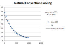
Here is the raw temp data for the ESC cooling down.
This is the rough numbers for the heat capacity of the ESC.
I am just summing up the product of mass and specific heat for the major components.
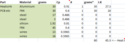
Now I assume that all the heat is lost via convection or conduction. That means the rate of heat loss is proportional to the heat difference between the controller and the environment. So I will assume an exponential decay. Here is the data fitting:
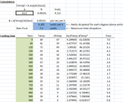
This gives a rough estimmate of 0.105 Watts/deg C. So for an ambient temp of 22 and max temp of 90, this gives a maximum continuous power dissipation of 7 watts.
Now lets look at what is happening when the controller is actually running a motor at full throttle.
Load case is ~1.0 Nm load, 23 battery amps, 22.2V, 100% throttle.
Here is the raw data.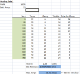 View attachment 4
The temp rise curve above ambient.
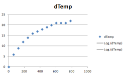
Then I adjust a manually entered stable temperature, until the curve fitting gives me the best R^2 value, for an exponential curve fit. Rsulting in this.
View attachment 2
This gives me an estimate of the amount of waste heat the controller is generating, 2.5Watts, and that the thermal equilibrium temperature will be 24 deg-C above ambient.
Next I look at a partial throttle scenario. Similar torque levels, but at half throttle. Battery Amps = 13.1, Phase Amps ~=26.2.
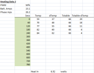
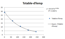
Waste heat is estimated at 6.9 watts, with thermal equilibrium at 66 deg-C above ambient.
Lets look at how this all applies to some of the test dat I collected for the Turnigy dlux 100 Amp ESC.
Here is the raw temp data for the ESC cooling down.

This is the rough numbers for the heat capacity of the ESC.
I am just summing up the product of mass and specific heat for the major components.

Now I assume that all the heat is lost via convection or conduction. That means the rate of heat loss is proportional to the heat difference between the controller and the environment. So I will assume an exponential decay. Here is the data fitting:

This gives a rough estimmate of 0.105 Watts/deg C. So for an ambient temp of 22 and max temp of 90, this gives a maximum continuous power dissipation of 7 watts.
Now lets look at what is happening when the controller is actually running a motor at full throttle.
Load case is ~1.0 Nm load, 23 battery amps, 22.2V, 100% throttle.
Here is the raw data.
 View attachment 4
The temp rise curve above ambient.

Then I adjust a manually entered stable temperature, until the curve fitting gives me the best R^2 value, for an exponential curve fit. Rsulting in this.
View attachment 2
This gives me an estimate of the amount of waste heat the controller is generating, 2.5Watts, and that the thermal equilibrium temperature will be 24 deg-C above ambient.
Next I look at a partial throttle scenario. Similar torque levels, but at half throttle. Battery Amps = 13.1, Phase Amps ~=26.2.


Waste heat is estimated at 6.9 watts, with thermal equilibrium at 66 deg-C above ambient.
adrian_sm
1 MW
Motor Thermal Modelling
Okay if I can do it for the ESCs why not try it on the motors.
Now I always assumed that the waste heat in a motor was directly proportional to the square of the torque being generated, or in effect the square of the phase current.
But when I reviewed the temperature data from the dyno I started to see some weird things.
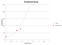
Here is the rough stable temp for a couple of different load levels created by using different regen levels with identical setup otherwise.
If I extrapolated a square law curve, based on one of the data points, it is way off the other. This looks more like a linear relationship.
Hmmm. Looks like I need to go back to the basics, to understand what is happening.
Now I also found some interesting effects that appear to be related to not only the average torque level, but the way in which the torque is generated.
Here is motor temperature I measured when pointing an IR thermometer at the windings past the rotating end bell for various load conditions.
So the weird thing is the drive motor seemed to increase in temperature a lot more when at partial throttle, but the regen motor did not.
Okay if I can do it for the ESCs why not try it on the motors.
Now I always assumed that the waste heat in a motor was directly proportional to the square of the torque being generated, or in effect the square of the phase current.
But when I reviewed the temperature data from the dyno I started to see some weird things.
Here is the rough stable temp for a couple of different load levels created by using different regen levels with identical setup otherwise.
If I extrapolated a square law curve, based on one of the data points, it is way off the other. This looks more like a linear relationship.
Hmmm. Looks like I need to go back to the basics, to understand what is happening.

Now I also found some interesting effects that appear to be related to not only the average torque level, but the way in which the torque is generated.
Here is motor temperature I measured when pointing an IR thermometer at the windings past the rotating end bell for various load conditions.
Code:
Motor: SK3 6364-190kv

Throttle,  Avg [N.m],    Drive Motor Temp [deg C], Regen Motor Temp [deg C]
100%        0.97         59                         57
95%         0.96         61                         61
50%         1.08         70                         60
So the weird thing is the drive motor seemed to increase in temperature a lot more when at partial throttle, but the regen motor did not.
Code:
Motor: SK3 6374-168kv

Throttle,  Avg [N.m],    Drive Motor Temp [deg C], Regen Motor Temp [deg C]
100%        0.95         59                        56
95%         0.95         60                        58
50% 1.07 67 62You are plotting generated torque and not just output torque?adrian_sm said:Motor Thermal Modelling
Now I always assumed that the waste heat in a motor was directly proportional to the square of the torque being generated, or in effect the square of the phase current.
adrian_sm
1 MW
I am not familiar with the terminology. What is the difference?
I am plotting measured output torque, so it does not take into account the motor internal losses to just spin to dyno at speed.
I am plotting measured output torque, so it does not take into account the motor internal losses to just spin to dyno at speed.
adrian_sm
1 MW
No load currents for the drive motor were around 2.17 Amps at 22.2V, or ~0.01Nm, so I just ignored it.
The torque to spin the generator motor are measured so taken in to account.
I didn't think the error of the assumptions above would be enough to explain the difference I saw.
The torque to spin the generator motor are measured so taken in to account.
I didn't think the error of the assumptions above would be enough to explain the difference I saw.
0.1 Nm Right?adrian_sm said:No load currents for the drive motor were around 2.17 Amps at 22.2V, or ~0.01Nm, so I just ignored it.
adrian_sm
1 MW
Ooops. Yes 0.1Nm at full speed.
[EDIT] But this loss is roughly the same for both the 1.0 & 1.3 Nm load cases, so still doesn't explain the non- square law heating.
[EDIT] But this loss is roughly the same for both the 1.0 & 1.3 Nm load cases, so still doesn't explain the non- square law heating.
If you could set up to measure the reaction torque on the drive motor, this would be the generated torque. It would give you a handle on the parasitic torque variable - it does go up a bit with output torque...
Also, the temperature of the coils isn't a perfect measure of losses. I think you need to take the thermal gradient into account, too?
Also, the temperature of the coils isn't a perfect measure of losses. I think you need to take the thermal gradient into account, too?
adrian_sm
1 MW
The only difference would be the bearing losses external to the motor. Right?Miles said:If you could set up to measure the reaction torque on the drive motor, this would be the generated torque. It would give you a handle on the parasitic torque variable - it does go up a bit with output torque...
To do it I would have to add an extra support bearing on the drive motor axle. Increasing the parasitic losses, but at least directly measuring those external to the motor.
Agreed. You can see it pretty clearly as you watch the temperature closely when it cools. Initially you can see the surface temp of the windings increase, before cooling.Miles said:Also, the temperature of the coils isn't a perfect measure of losses. I think you need to take the thermal gradient into account, too?
But for the constant load test I let the temperatures stabilise for about 10 minutes for each load state, and take the final temp reading before I change load states. So internal gradients should hae sorted themselves out by then, and we should be back to close to heat loss being proportional to temperature difference. Not perfect but again I didn't think it was enough to explain the discrepancy.
adrian_sm
1 MW
Miles said:I'm very interested to see how the losses in the drive motor relate to the ESC duty cycle........
That one threw me too. Seemed very consistent that the drive motor heated up more when I had a lot of PWM.
But I need to get the phase current estimates closer before reading in to it too much.
I guess the discrepancy is the result of the compounding of all these apparently insignificant factors....adrian_sm said:Not perfect but again I didn't think it was enough to explain the discrepancy.
I guess that was to be expected, especially with trapezoidal drive. It would be interesting to see what the gains would be from using sine drive at high PWM rates.adrian_sm said:That one threw me too. Seemed very consistent that the drive motor heated up more when I had a lot of PWM.Miles said:I'm very interested to see how the losses in the drive motor relate to the ESC duty cycle........
adrian_sm
1 MW
Yeah yeah. Okay. I'll go quantify them.
While I am at it, I ahve learnt my reaction torque meaurements are affected by the way I zero the scales.
Depending on where the motors cog to rest, can apply a different load on the scales when I zero them before I start a run. Not sure how other have dealt with this. But you need to zero them, because even the weight of the phase wires can be trying to turn the motor on it axle. So you ahve to be careful that the controllers don't move and load up the phase wires. Maybe I should detach the torque arm from the scales let the motor "cog" to a natural resting point them mold up my bluetak to attach it to the scales.
adrian_sm
1 MW
Miles said:I guess that was to be expected, especially with trapezoidal drive. It would be interesting to see what the gains would be from using sine drive at high PWM rates.adrian_sm said:That one threw me too. Seemed very consistent that the drive motor heated up more when I had a lot of PWM.Miles said:I'm very interested to see how the losses in the drive motor relate to the ESC duty cycle........
Can you explain why?
BTW. I might be testing out one of the LSDZS sensorless FOC sine-wave controllers soon, but don't have my hands on it yet.
Similar threads
- Replies
- 15
- Views
- 5,458
- Replies
- 1
- Views
- 400
- Replies
- 35
- Views
- 8,119


