Eastwood’s first battery build

Does anyone have suggestions for the charger connector for my 28s battery? Looking for something that’s waterproof and has a spring lid/cover.
More than likely, will be installing the charging port where the gas cap used to be on my Rmz conversion.

I’ve found plenty of standard EV charger ports for cars but they’re too big, need something more compact.
Do you have access to CAD and a 3d printer? I'm planning, for my Ninja build, to copy the design of the gas cap in PETG, while also incorporating it as a housing for an XT90 or Anderson. If I'm successful I can share it later.
 
Do you have access to CAD and a 3d printer? I'm planning, for my Ninja build, to copy the design of the gas cap in PETG, while also incorporating it as a housing for an XT90 or Anderson. If I'm successful I can share it later.

Thank you for the offer, my friend! 😀
Unfortunately, no I don’t have access to a 3-D printer. I certainly need to get a 3-D printer set up as I’ve needed one for various types of hobbies over the years.

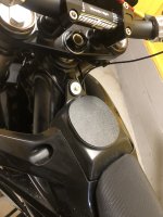
That being said, I’ve already cut the gas cap port off flush with the tank and I’m using a flat piece of ABS plastic covering the hole. Plan to just find a charger port/connector with a spring loaded door to screw into the flat ABS plastic. Probably will add a small voltage display in conjunction with the charger port.

Here’s a couple of pictures as it’s not finished yet, need to still clean up the edges and just have it hot glued in place for the moment. I’ll use a two part epoxy once I have the final shape.


57AFDDBE-16B8-4ED9-8CE2-C34F07BE419C.jpeg

563448C8-E023-4EB5-9BAE-EB679E1DDBBD.jpeg
 
Thank you for the offer, my friend! 😀
Unfortunately, no I don’t have access to a 3-D printer. I certainly need to get a 3-D printer set up as I’ve needed one for various types of hobbies over the years.

That being said, I’ve already cut the gas cap port off flush with the tank and I’m using a flat piece of ABS plastic covering the hole. Plan to just find a charger port/connector with a spring loaded door to screw into the flat ABS plastic. Probably will add a small voltage display in conjunction with the charger port.

Here’s a couple of pictures as it’s not finished yet, need to still clean up the edges and just have it hot glued in place for the moment. I’ll use a two part epoxy once I have the final shape.


View attachment 336346

View attachment 336347
You could also do what I did with my last gas cap, before I had a printer: rig up something to position your charge port of choice in the hole, then fill all around it with silicone and/or potting compound.

Not too crazy about the red cap lol
Paint!
 
If you install it under the actual gas cap, so the gas cap can still be used, it will seal the opening. That's been done on at least a couple of builds here.

Other than that, there's a few kinds of waterproof caps you can install on various panel-mount connector types.

Electrically it's better to pick the connector type you want to use, then find the waterproof cover for it, but if the waterproofing is more important than the electrical and connection properties, you can find the cover you like first, then use a connector that fits under that cover.

If you don't mind the DIY, you can use a connector you like, install it in a piece of threaded PVC that mounts where you want it, and just screw on the PVC cap. (or steel, or whatever material you like). hardware stores / lowes / hd / etc will have a selection of such things you can adapt. :)

Wierd...When I posted this yesterday there werent' any other replies between mine and your question, but today there are several...and it says I posted this just now? :?
 
Wierd...When I posted this yesterday there werent' any other replies between mine and your question, but today there are several...and it says I posted this just now? :?

Yeah strange..


Also found this, says 50amps but at 48v. I’m not sure how these connectors are even rated for voltage? Wonder if this would work with 117v?

So 50a x 48v -= 2,400watts
So maybe if you stay under 2,400w its good with higher voltage, not sure 🤔

https://a.co/d/9U4UBpw
 
A connector will "work" at any voltage as long as there is no current flowing during connect or disconnect, *and* the contacts are far enough apart on either half to prevent arc between them, and any insulation on them is rated (or at least capable) of blocking the desired voltage.

If current can flow (like caps in a controller when you connect a battery, or caps in a charger when you plug it in, etc) you might want a precharge circuit on any connector that is not designed with sacrificial tips (such as anderson PP / SB contacts).

If contacts are too close together, you could end up with arcing if the voltage is high enough. There are charts around the web determining distance required between conductors to prevent that.


Connectors also don't really have a wattage....it doesn't work that way. The voltage and current ratings are separate things, not intended to be used to make a wattage. To calculate a wattage if you needed one you'd need to determine the voltage drop across the contacts at the max current you would use them at, then multiply *that* voltage by that current, to see how many watts of heat are lost in *each contact*, multiply by number of contacts. How well the connector dissipates heat in a specific usage would then let you determine a power rating for it (enclosed would be less than with airflow or other cooling, etc).


They have a current limit because of the conductor size and contact resistance--if that resistance is very low and conductors are large enough, you can use high currents thru them, but it is safest to stay below their ratings, as those ratings may include a safety factor for poor contact alignment, etc. that increases the resistance.
 
A connector will "work" at any voltage as long as there is no current flowing during connect or disconnect, *and* the contacts are far enough apart on either half to prevent arc between them, and any insulation on them is rated (or at least capable) of blocking the desired voltage.

Yeah makes sense.
With this connector, it looks like the pins are fairly far apart, more than my current connectors for my 72 V system. Hopefully these are far enough apart for 117v

If current can flow (like caps in a controller when you connect a battery, or caps in a charger when you plug it in, etc) you might want a precharge circuit on any connector that is not designed with sacrificial tips (such as anderson PP / SB contacts).

With my current chargers 72v, I plug in the wall to fill the caps and then unplug it before connecting to the actual battery. Once connected to the battery, I then plug it back into the wall. This has always prevented the spark for me. I guess that’s one way of pre-charging the caps in the charger?

They have a current limit because of the conductor size and contact resistance--if that resistance is very low and conductors are large enough, you can use high currents thru them, but it is safest to stay below their ratings, as those ratings may include a safety factor for poor contact alignment, etc. that increases the resistance.

Plan as of now it’s not charge with too much current as I shouldn’t need fast charging since I’m building a large battery that should give plenty of range.

But yeah, all makes sense, a poor design that would have poor contact alignment to the pins would limit the current rating by increasing the resistance.
 
Wonder if this 1.5 insulating board would be enough for insulating between each ply/level? Obviously using it for the insulating factor but also it will be weight-bearing, more so the lower levels. Plan to use kapton tape over the busbars then fishpaper followed by this insulating board. I’ve played around with different ideas of different methods between each ply while maintaining the battery short as possible. As mentioned, space is limited.

1.5MM-thick
https://a.co/d/50g6Bm7
 
Wouldn't you use one on each side for better separation no matter what thickness and with a charger you plug it into the battery first or do you plug it into the wall first and then the battery and are you going to charge at 1:20v or 240v and where ?
Plus I like that charger it looks interesting.
I have three 24 volt meanwhile stacked for 84 volt at 15.5 amps the max my 120 circuit can take how I know if I plug anything else in trips a circuit oh plus I'm a very long extension cord good luck keep posting please.
 
Wouldn't you use one on each side for better separation no matter what thickness

Yeah, I could go with one piece on each end like you’re suggesting. Then just go to 1mm thick on each. Also use the kapton tape to hold the insulating boards in place to the end of each cell blocks.
and with a charger you plug it into the battery first or do you plug it into the wall first and then the battery and are you going to charge at 1:20v or 240v and where ?

will be charging at 120v
I plug into the wall first to charge the caps, then unplug from the wall. Next connect to the battery and then back to the wall. I’m not sure if this is the best method, but it prevents the spark.
 
I don't see the need for unplugging from the wall then replugging after pack connection?

Wonder if this 1.5 insulating board would be enough for insulating between each ply/level? Obviously using it for the insulating factor but also it will be weight-bearing, more so the lower levels. Plan to use kapton tape over the busbars then fishpaper followed by this insulating board. I’ve played around with different ideas of different methods between each ply while maintaining the battery short as possible. As mentioned, space is limited.

1.5MM-thick
https://a.co/d/50g6Bm7
Can't tell for sure but it looks like regular "FR4" as is used in PCBs?
 
I don't see the need for unplugging from the wall then replugging after pack connection?

Right
Can't tell for sure but it looks like regular "FR4" as is used in PCBs?

Actually, I think this 3240 is cheaper than the FR-4. Looks like the FR-4, “FR” flame retardant is better insulator than the 3240.

Do you have any recommendations for insulating between cell blocks?

May just go with the FR-4 fiber board, but still contemplating 🤓
200x300x1.0mm Yellow FR4 Glass Fiber Board, Epoxy Resin Board https://a.co/d/hyR5TEd
 
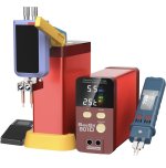
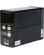
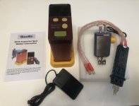
Finally pulled the trigger on a spot welder. Amazon had 20% off yesterday so went for it. Was able to get a 4 year warranty for an additional $45. I went with this one for the simple fact you can plug it into an AC power source, also it has two capacitors built-in. I’ve seen good reviews on different platforms with this spot welder, so I figured I would give it a shot. There are several companies that sell this spot welder rebranded with their brand, but they’re all the same internals.

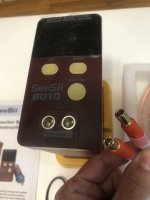
SeeSii 801D Spot Welder, 12KW Capacitor Energy Storage
https://a.co/d/5TpJDps
1F0B8A0B-CCD1-408B-A010-75A2664225DF.jpeg
 
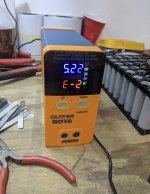
Got the spot welder in. Will do lots of practice welds on some old salvaged 18650 cells. Really like the fact that this can be plugged into a AC power source. The manual says charging time is 20 minutes to fill the capacitors.

195C0E1B-25C2-4365-B9EE-DEFEBFDB93DA.jpeg


23277D26-5A66-46FD-ABA5-65C010ED6324.jpeg

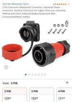
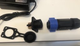
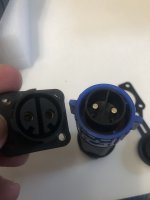
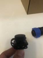
Also received the charger port, that will be for the battery. Definitely looks like it can handle some current, probably won’t charge past 25 A max, although the cells can take much more being 11 parallel. This connector/charger port is rated at 50amps.

CD269340-74F1-4983-81DF-EFF546F518E7.jpeg

4E37CE6D-4E43-4E13-9269-E28291C1D5DB.jpeg

The lid for the charger port is made of rubber, Seals really nice. This connector is rated at IP 67

1F63C22A-DB0B-4903-9202-22FEEC4D720F.jpeg
 

Attachments

  • C71FDD03-8B9B-469D-9F4F-C3B3878C1A03.jpeg
    C71FDD03-8B9B-469D-9F4F-C3B3878C1A03.jpeg
    1.2 MB · Views: 1
If you mean milliohms, maybe, but if you actually mean ohms, those cells would be great space heaters. ;)


While "acceptable" depends on each person's definition depending on their usage, that is a whole lot less variation (by at least an order of magnitude or two) than what many people building packs get when cell testing. My guess is that it is good enough.

The way the cells will behave under load and charge will vary proportionally with the differences between them. The less difference, the more consistently the behavior across the pack, and the better it stays balanced on it's own, and the more usable the pack is for longer.
 
If you mean milliohms, maybe, but if you actually mean ohms, those cells would be great space heaters. ;)

Yes I meant milliohms 😅 not ohms.

While "acceptable" depends on each person's definition depending on their usage, that is a whole lot less variation (by at least an order of magnitude or two) than what many people building packs get when cell testing. My guess is that it is good enough.

The way the cells will behave under load and charge will vary proportionally with the differences between them. The less difference, the more consistently the behavior across the pack, and the better it stays balanced on it's own, and the more usable the pack is for longer.
makes sense 👍


So what would be an example of cells that are not evenly matched when it comes to milliohms? Trying to learn for future battery builds of what would not be excepted.

Just an example: 9.25 then maybe 10.25 milliohms something that far apart?
 
Back
Top