I think we've already discussed the contactor-based BMSs (whcih is what I would use for a high current EV), but if not, there's a few threads and posts they're discussed in around the forum.
You are using an out of date browser. It may not display this or other websites correctly.
You should upgrade or use an alternative browser.
You should upgrade or use an alternative browser.
Eastwood’s first battery build
- Thread starter Eastwood
- Start date
999zip999
100 TW
How would you connect your battery to your controller a pre-resistor or some type of contact made for a boat ? Some controllers I read you can charge thru the one leg of your phase wire and ?
Eastwood
100 kW
- Joined
- Jan 13, 2021
- Messages
- 1,479
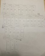
Well, think I’ve figured out the battery configuration after changing it about 10 times lol. This battery configuration is a tight fit, but should fit just right with enough room for a battery box. I really wanted to go with more cells but I just don’t want too heavy of a trail bike so I’ll settle for 308 cells 28s 11p.
Will order the WELLGO copper busbars extra long for the series connections between each ply and cut and bend to make the series connections between each ply. Plan to bolt the connections together at each ply/level.
This drawling is from the left side of the bike
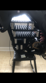
Then here’s a picture of the actual battery, well just the skeleton of the battery.
Will order the WELLGO copper busbars extra long for the series connections between each ply and cut and bend to make the series connections between each ply. Plan to bolt the connections together at each ply/level.
This drawling is from the left side of the bike

Then here’s a picture of the actual battery, well just the skeleton of the battery.

999zip999
100 TW
Ok is that 77lbs or 770lbs math . Ok that's doable oh pust packing and BMS some Bms's are 4-5lbs .oh and copper. Adding up.
Eastwood
100 kW
- Joined
- Jan 13, 2021
- Messages
- 1,479
I’m not sure what you’re asking about the 77 or 770?Ok is that 77lbs or 770lbs math . Ok that's doable oh pust packing and BMS some Bms's are 4-5lbs .oh and copper. Adding up.
The battery cells themselves should weigh right at 45lbs with 308 cells. And then I guesstimate no more than 60lbs total including the BMS, copper busbars, battery box etc.
999zip999
100 TW
Oh that's a lot better I read the stat sheet and they said
7 g a cell times 308 ?
7 x 308 = 2.1560g. 2.156 divided by 28 = 77
Maybe I got it real wrong thanks for the correction
7 g a cell times 308 ?
7 x 308 = 2.1560g. 2.156 divided by 28 = 77
Maybe I got it real wrong thanks for the correction
999zip999
100 TW
Oh 770g divided by 16 oz eagles 48 lb that's a whole lot of math I hope I think I figured out rightOh that's a lot better I read the stat sheet and they said
7 g a cell times 308 ?
7 x 308 = 2.1560g. 2.156 divided by 28 = 77
Maybe I got it real wrong thanks for the correction
Eastwood
100 kW
- Joined
- Jan 13, 2021
- Messages
- 1,479
So I finally ordered the busbars after lots of contemplating. Here’s the drawling from WELLGO, what do you all think?
The connections between each ply is difficult because I’m tight on space. The busbars will come extra long where the connections are made between each ply/level. I will have to bend, shape and cut to make the connections, then will bolt together between each ply. I’ve considering soldering the ply connections instead of bolting them together, but I think that would just create more IR with soldering.
Thoughts?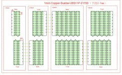
Here’s a picture of one of the discharge busbars. Well just a paper version lol. I will bend it at 90° because there’s not enough room to go beyond the pack. I have just enough room to build a battery box.
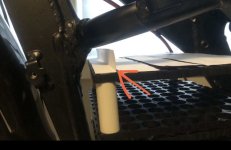
Is there any other way to connect the discharge wire to that busbar without soldering? I plan to run the wire stripped all the way across the busbar.
The connections between each ply is difficult because I’m tight on space. The busbars will come extra long where the connections are made between each ply/level. I will have to bend, shape and cut to make the connections, then will bolt together between each ply. I’ve considering soldering the ply connections instead of bolting them together, but I think that would just create more IR with soldering.
Thoughts?

Here’s a picture of one of the discharge busbars. Well just a paper version lol. I will bend it at 90° because there’s not enough room to go beyond the pack. I have just enough room to build a battery box.

Is there any other way to connect the discharge wire to that busbar without soldering? I plan to run the wire stripped all the way across the busbar.
Last edited:
You can bolt it on. Crimp a good double-ring terminal (also called ring-tongue)

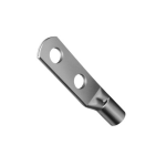
to the wire, then drill matching holes in the busbar, bolt, nut, lockwashers, done.
Don't use this kind; twisting forces will tear the contact off the rings:
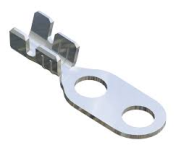
(I used nylock nuts to bolt my wiring to my busbars on the SB Cruiser's pack (the spares of which are often used on my DIY e-mower conversion), but I made sure that everything is sized to not warm up at all so the nylocks can't soften and loosen.
I'll edit in some pics if I can find them.


to the wire, then drill matching holes in the busbar, bolt, nut, lockwashers, done.
Don't use this kind; twisting forces will tear the contact off the rings:

(I used nylock nuts to bolt my wiring to my busbars on the SB Cruiser's pack (the spares of which are often used on my DIY e-mower conversion), but I made sure that everything is sized to not warm up at all so the nylocks can't soften and loosen.
I'll edit in some pics if I can find them.
Eastwood
100 kW
- Joined
- Jan 13, 2021
- Messages
- 1,479
You can bolt it on. Crimp a good double-ring terminal (also called ring-tongue)
Thank you sir, for the input!
I could use more than one of those double-ring terminal. Maybe three of them, one on each side and then another double ring terminal in the middle of the busbar. So basically 3 wires crimped to the one discharge wire.
I plan on buying a good quality crimper. I’m trying not to use any solder for this build, maybe except for the balance wires.
Eastwood
100 kW
- Joined
- Jan 13, 2021
- Messages
- 1,479
I wonder if they make a really long terminal with multiple holes like 5 or so. If I can find something like that, it would be simpler with just connecting one wire to each busbar.
If not, I could do the other option with using maybe 3 double ring terminals connected to the busbar that lead into one wire. I’m trying to do everything overkill with this battery build, hoping for the less voltage sag as possible.
If not, I could do the other option with using maybe 3 double ring terminals connected to the busbar that lead into one wire. I’m trying to do everything overkill with this battery build, hoping for the less voltage sag as possible.
You can make your own; use the pictures of the two-hole versions as a guide to how they should look, more or less.
Buy copper or brass tube of the right diameter and wall thickness to fit securely over your wire conductors.
Cut it so you have enough length for the amount of conductor you will crimp into the tube, plus enough for the length of the flat part that will bolt to the busbar.
Crimp the tube to the wire.
Hammer or otherwise flatten the tube for the rest of it's length past the conductor.
Mark and drill your holes, as small as you can make them vs the width of the flat part as you can mechanically get away with, to leave as much crossection around the holes as possible.
Since the surface of the now-flat tube is not going to be really truly flat without a compression-die to do that job, you will probably have to file or otherwise make that surface flat and parallel to mate as closely as possible with your busbar face; more contact area is better, as that's where the current will flow thru to get to the discharge cable.
Using two bolts inline as I was showing is more for ensuring the cable can't pull on the ring terminal "sideways" (yaw around the bolt center) in a way that could loosen the hardware and decrease the contact pressure (increasing contact resistance), though if you have sufficient contact surface area of the hardware heads/washers to the flat area, and to the busbar, then more bolts can increase the electrical contact area and decrease contact resistance. But a larger surface area single-bolt ring terminal will do the latter the same way.
Not sure why you would need multiple wires per busbar, unless the busbars and/or wires are not sufficient crosssection to pass the current your system will require.
Eastwood
100 kW
- Joined
- Jan 13, 2021
- Messages
- 1,479
Yeah, was thinking of just making my ownYou can make your own; use the pictures of the two-hole versions as a guide to how they should look, more or less.
Great idea! maybe put the cut flat section in a vice to help flatten. And I could use sandpaper on the backside of a piece of glass on the mating surface to get it completely flat.Buy copper or brass tube of the right diameter and wall thickness to fit securely over your wire conductors.
Cut it so you have enough length for the amount of conductor you will crimp into the tube, plus enough for the length of the flat part that will bolt to the busbar.
Crimp the tube to the wire.
Hammer or otherwise flatten the tube for the rest of it's length past the conductor.
Using two bolts inline as I was showing is more for ensuring the cable can't pull on the ring terminal "sideways" (yaw around the bolt center) in a way that could loosen the hardware and decrease the contact pressure (increasing contact resistance), though if you have sufficient contact surface area of the hardware heads/washers to the flat area, and to the busbar, then more bolts can increase the electrical contact area and decrease contact resistance.
Are you saying that by using just a single mounting bolt would offer the same even current flow VS having multiple bolts? I get what you’re saying by using two bolts on the lug to prevent from the discharge wire, wiggling the single bolt loose.But a larger surface area single-bolt ring terminal will do the latter the same way.
Well was thinking by using a few discharge wires from the busbar would create less of a hotspot in one area. So basically would have more even current flow throughout the whole bus bar not just on one side.Not sure why you would need multiple wires per busbar, unless the busbars and/or wires are not sufficient crosssection to pass the current your system will require.
Just a thought though, you certainly know a lot more about this than me
Last edited:
Are you saying that by using just a single mounting bolt would offer the same even current flow VS having multiple bolts? I get what you’re saying by using two bolts on the lug to prevent from the discharge wire, wiggling the single bolt loose.
If the pressure from the bolt head is correctly spread by the hardware between it and the lug, and mating surfaces of both lug and busbar are flat-parallel, then yes, the current flow across the mating surfaces would be even.
If the surfaces have variations in electrical resistance, then there will be variations in current flow. (just like with heatsinks and heatflow vs thermal resistance).
If the resistance of the connection is correctly low, it won't have any hotspots.Well was thinking by using a few discharge wires from the busbar would create less of a hotspot in one area. So basically would have more even current flow throughout the whole bus bar not just on one side.
Just a thought though, you certainly know a lot more about this than me
And if the resistance of the busbar and the cable is equal, there isn't any bottleneck for current either (assuming they're sufficient for the current flow desired).
Batteries have been built by various people with multiple space-apart discharge wires, with no problems I'm aware of, but I don't know if any of them were ever tested that way vs a single wire at a single point on the busbar, so I don't know how much (if any) difference it makes.
The disadvantage of multiple wires is that they then have to be joined together at some point, and that point is one more interconnect and associated resistance, except if all of them are run all the way from the busbar to the destination (controller input, for instance), and all bolt to the same lug point there, in a stack. (as long as the stack itself isn't adding significant resistance, meaning the surface area is sufficient for the current, etc).
Last edited:
Eastwood
100 kW
- Joined
- Jan 13, 2021
- Messages
- 1,479
So I’m contemplating what type of insulation sheets I will use between each ply.. Seems like a lot of battery builders use fiber board but I was thinking of using some rubber sheets as well to help with vibration. So maybe could use a sandwich method of fiberboard in the middle, and then rubber sheets on the top and bottom that would lay against the copper busbars. Also considered using ABS plastic sheets between each ply with the rubber sheets..
What are your guys thoughts on this?? Open to ideas and suggestions. I can’t get too thick between each ply because it’ll make the battery too tall.
The fiber board would be enough to prevent a short circuit, but I’m thinking the rubber in addition would help with vibration since this is a heavy battery. Something really thin like 1mm rubber sheets. Which would give me 2 mm of rubber between each ply for vibration.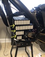

Will the rubber be proof against being cut into by the cell holders, etc? If not, you will probably be better off using two layers of hard stuff with the rubber between them to protect it.
Eastwood
100 kW
- Joined
- Jan 13, 2021
- Messages
- 1,479
Yeah good point about the rubber cutting into the cell holders etc… So the rubber in the middle of the fiber board might be better like your suggesting, then I could use slightly thicker rubber (2 or 3mm) since there will only be one layer in the middle.Will the rubber be proof against being cut into by the cell holders, etc? If not, you will probably be better off using two layers of hard stuff with the rubber between them to protect it.
Yes, but the fiberboard would be doubled up, and would make the stack taller. Thinner fiberboard would help that, but if you were already using the thin stuff....
Oh, also, I hadn't thought about it before, but if you did have the rubber right on the cell block, it would compress and could sit hard enough against hte cell tops to put pressure on the cell ends. I don't know what effect that has on them, but its' a thought.
Oh, also, I hadn't thought about it before, but if you did have the rubber right on the cell block, it would compress and could sit hard enough against hte cell tops to put pressure on the cell ends. I don't know what effect that has on them, but its' a thought.
Eastwood
100 kW
- Joined
- Jan 13, 2021
- Messages
- 1,479
Yes, but the fiberboard would be doubled up, and would make the stack taller. Thinner fiberboard would help that, but if you were already using the thin stuff....
Oh, also, I hadn't thought about it before, but if you did have the rubber right on the cell block, it would compress and could sit hard enough against hte cell tops to put pressure on the cell ends. I don't know what effect that has on them, but its' a thought.
So maybe .5mm fiberboard if I can find it. Then I found some neoprene rubber on Amazon that comes in 0.125” or 0.062”. The thicker neoprene would give me more shock absorption, but it might make the battery too tall also considering the busbars are 1mm thick.
Are you looking for shock absorption, or just vibration damping?
If the latter, a flexibly-dense heavy solid rubber would work better for such a thin layer.
I don't know what it's called, but I have a very small sheet here that was sent to me with my EIG cells, sized such that I think it was used on one end of one of the cell stacks. It feels almost like "rubber lead", if that makes any sense; if you can imagine pizza dough made of lead. :lol: Very heavy for it's ~2mm thickness; it might be impregnated with metal particles to cause that, but you wouldn't need those unless you're also looking to conduct heat (probably not).
Eastwood
100 kW
- Joined
- Jan 13, 2021
- Messages
- 1,479
Are you looking for shock absorption, or just vibration damping?
All of the above really. My first thought for using the rubber is to absorb the weight of the battery since it’s stacked 4 ply. Especially the very bottom cell block will be absorbing most of the weight. In addition, it seems that it would help take some of the stress off the spot welds, since there will be somewhat of give between each ply.
But yeah, also to help with vibration from riding off road as well. Plan on using a thicker rubber on the sides of the battery to help absorb impacts when the bike is dropped, which can happen often when riding gnarly enduro trails.
If the latter, a flexibly-dense heavy solid rubber would work better for such a thin layer.
Yeah good point!
Although it seems that the neoprene rubber is always marketed as shock absorbing. I guess it would be similar as actual suspension, the heavier the weight, the more stiff/density would be needed to help with dampening.
I don't know what it's called, but I have a very small sheet here that was sent to me with my EIG cells, sized such that I think it was used on one end of one of the cell stacks. It feels almost like "rubber lead", if that makes any sense; if you can imagine pizza dough made of lead. :lol: Very heavy for it's ~2mm thickness; it might be impregnated with metal particles to cause that, but you wouldn't need those unless you're also looking to conduct heat (probably not).
Yes, the lead pizza dough analogy makes sense lol
As mentioned above, the bottom cell block will be absorbing most of the weight, but the backside of the battery will be sitting on top of the motor mount so that’ll take some of the weight off the very bottom cell Block.
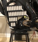
Although I need to trim down that top motor mount a few millimeters as it has the battery slightly leaning forward. I won’t remove the top motor mount completely because the bottom side of the battery case will connect to that top motor mount.
Last edited:
What exactly do you mean?My first thought for using the rubber is to absorb the weight of the battery
There isn't a way to absorb static weight (that would require antigravity
Some thoughts on how these things do work (though I don't know the detailed materials science behind it all, or any of the math):
If you are trying to absorb vertical shocks, then you need something that absorbs energy, which typically is done by compressing the something and storing that energy either within the structure as deformations or as heat, then releases that energy back once the source of energy is removed (end of bump, etc), decompressing the something in the process. (almost always there is some permanent compression/deformation, and this can increase over time each time the permanent-limit of the material is exceeded.
To do this, it has to be either dense enough or thick enough to take all the energy from everything above it that can move. If you have a multilayer stack, then you would need a layer proportionally thicker than the one on the layer above it, all the way down to the bottom, or proportionally denser. (because each layer adds another set of masses above it, until the last layer has to support the entire battery mass).
To have it actually do something predictable (which is useful), you'd need to either test different materials with equivalent masses per surface area on them with a known and replicable vertical displacement, to see which materials can handle the situation you expect them to have to, or use the situational info and material specs from companies making it to calculate what you'd need, and in what thickness. That's a lot of work, either way.
But without doing one or both of those, you don't really know what, if anything, the materials will do in regards to what you *want* them to do. It could be that it'll do everything you want just by trying the first thing...or it might do nothing at all, but either way you won't actually know what it's doing (unless you are really interested in finding out by instrumenting the pack in a way that tells you what is happening, and/or failures occur because of things that should ahve been prevented, so that you then know it *didn't* work.
So for the purpose of minimizing vertical shocks, and to save material/weight/cost/size, it would be better to connect all the layers together in a way that locks them to each other and just prevents any movement between them. Then you only need shock absorption in the bottom under pack layer, below all the cells. This is better for inter-layer interconnects, too, since that way they will see less flexing and movement, and be less likely to have any form of stress failures at the interconnect connection points, or wherever it flexes.
For vibration damping, then something with compression in the same manner as the above isn't as important as something taht just absorbs the vibration energy (usually by warming up), so a solid rubber probably works better than a foam, depending on the characteristics of the rubber, since the vibrations aren't just going to be vertically-oriented, unlike most of the shock loading.
Yeah good point!
Although it seems that the neoprene rubber is always marketed as shock absorbing. I guess it would be similar as actual suspension, the heavier the weight, the more stiff/density would be needed to help with dampening.
All flexible material (including rubber) is shock absorbing in that it absorbs energy by flexure/compression/etc.
But even within neoprene there are different properties, and within other rubbers there is a wide variety of properties that may better suit your purposes.
Neoprene itself has a variety of densities, for instance, with different bubble sizes and ratios of rubber to air, and different qualities of the actual rubber. Some of it is very stretchy, and a lot of it will tear very easily if subjected to stretching, while taking thru-thickness compression very well.
While true of a direct vertical shock thru the mass of the layer, it isn't the case for shocks that result at an angle thru the pack forward--that places more of the shock energy into the much smaller lowest block layer. Exactly how it works out depends on how everything is interconnected and what materials are used, etc.As mentioned above, the bottom cell block will be absorbing most of the weight, but the backside of the battery will be sitting on top of the motor mount so that’ll take some of the weight off the very bottom cell Block.
Eastwood
100 kW
- Joined
- Jan 13, 2021
- Messages
- 1,479
What exactly do you mean?
There isn't a way to absorb static weight (that would require antigravity).
Oh.. I meant my initial thought of using rubber between each ply is to help with the downward/vertical pressure while riding. I’m saying this, because this is a lot of weight of multiple modules stacked on top of each other, so the rubber between would help absorb some of the downward pressure from riding Enduro. If I were building a bike for the street, I wouldn’t worry about this so much but there’s a lot of jarring, bouncing, etc. while riding through extreme off-road Enduro trails.
I mean truthfully, the rubber probably isn’t necessary, but I’m just trying to do everything overkill especially this being my very first battery build. The goal is to never have to reopen to make any modifications changes etc., so just trying to go through every little detail to make sure I get this 100% on the first attempt
Some thoughts on how these things do work (though I don't know the detailed materials science behind it all, or any of the math):
If you are trying to absorb vertical shocks, then you need something that absorbs energy, which typically is done by compressing the something and storing that energy either within the structure as deformations or as heat, then releases that energy back once the source of energy is removed (end of bump, etc), decompressing the something in the process. (almost always there is some permanent compression/deformation, and this can increase over time each time the permanent-limit of the material is exceeded.
To do this, it has to be either dense enough or thick enough to take all the energy from everything above it that can move. If you have a multilayer stack, then you would need a layer proportionally thicker than the one on the layer above it, all the way down to the bottom, or proportionally denser. (because each layer adds another set of masses above it, until the last layer has to support the entire battery mass).
To have it actually do something predictable (which is useful), you'd need to either test different materials with equivalent masses per surface area on them with a known and replicable vertical displacement, to see which materials can handle the situation you expect them to have to, or use the situational info and material specs from companies making it to calculate what you'd need, and in what thickness. That's a lot of work, either way.
But without doing one or both of those, you don't really know what, if anything, the materials will do in regards to what you *want* them to do. It could be that it'll do everything you want just by trying the first thing...or it might do nothing at all, but either way you won't actually know what it's doing (unless you are really interested in finding out by instrumenting the pack in a way that tells you what is happening, and/or failures occur because of things that should ahve been prevented, so that you then know it *didn't* work.).
So for the purpose of minimizing vertical shocks, and to save material/weight/cost/size, it would be better to connect all the layers together in a way that locks them to each other and just prevents any movement between them. Then you only need shock absorption in the bottom under pack layer, below all the cells. This is better for inter-layer interconnects, too, since that way they will see less flexing and movement, and be less likely to have any form of stress failures at the interconnect connection points, or wherever it flexes.
For vibration damping, then something with compression in the same manner as the above isn't as important as something taht just absorbs the vibration energy (usually by warming up), so a solid rubber probably works better than a foam, depending on the characteristics of the rubber, since the vibrations aren't just going to be vertically-oriented, unlike most of the shock loading.
All flexible material (including rubber) is shock absorbing in that it absorbs energy by flexure/compression/etc.
But even within neoprene there are different properties, and within other rubbers there is a wide variety of properties that may better suit your purposes.
Neoprene itself has a variety of densities, for instance, with different bubble sizes and ratios of rubber to air, and different qualities of the actual rubber. Some of it is very stretchy, and a lot of it will tear very easily if subjected to stretching, while taking thru-thickness compression very well.
While true of a direct vertical shock thru the mass of the layer, it isn't the case for shocks that result at an angle thru the pack forward--that places more of the shock energy into the much smaller lowest block layer. Exactly how it works out depends on how everything is interconnected and what materials are used, etc.
Yeah this is a lot more technical than I was thinking
This definitely gives me a lot to think about in regards of what type of material and density to use between each ply.
Your input and insight is always very appreciated!
Then you're looking for vertical shock load absorption (resisting momentary increases in apparent weight from the vertical increases in acceleration on bumps/holes/etc), not vertical weight absorption (antigravityOh.. I meant my initial thought of using rubber between each ply is to help with the downward/vertical pressure while riding. I’m saying this, because this is a lot of weight of multiple modules stacked on top of each other, so the rubber between would help absorb some of the downward pressure from riding Enduro. If I were building a bike for the street, I wouldn’t worry about this so much but there’s a lot of jarring, bouncing, etc. while riding through extreme off-road Enduro trails.
If you really want to do that with this rubber-sheet part, you'd have to determine how much energy is going to need to be absorbed by the damping material to damp as much as you want it to (however much that is), and find a damping material that will do that within the space limitations you have. There might not be such a material.I mean truthfully, the rubber probably isn’t necessary, but I’m just trying to do everything overkill especially this being my very first battery build. The goal is to never have to reopen to make any modifications changes etc., so just trying to go through every little detail to make sure I get this 100% on the first attempt
It might be easier to just put stuff in the pack layers to keep anything from moving around at all, and then somethng vibration-damping inside the casing around the entire pack that doesn't compress (so not a compressible foam) so it doesn't squish under the pack weight and then allow movements.
Then mount the pack to the frame in a way that lets the inertia of the pack keep it moving the way it already was when the frame moves some other way. With your space constraints that's probalby not really possible, but you could mount it on something similar to engine isolation mounts. Rubber blocks that fit around the bolts that secure it to the frame, with as much rubber thickness as you can fit between the bolt and the frame holes.
But if the pack actually contacts any part of the frame (or motor, etc), vibration and shock will be directly transmitted to the part of the pack that touches the frame, negating the effects of the mounting dampers.
But...as long as no internal part of the pack is able to move relative to any other internal part of the pack, it doesn't really matter, since nothing can be stressed that way. Only parts that move relative to each other can break, fail, disconnect, etc. because of the movement...
In the unlikely event that the cells themselves are internally made such that things inside can move (like jellyroll vs casing) then there could be issues, but if that were true there is nothing at all you can do about it other than isolating the entire pack from vibration and shock, which probably requires more space around it than you have available.
While I'm no engineer of any kind, I've broken or seen broken so very many things that I have learned quite a lot about how not to break them...and I still find novel ways to do it anyway. :lol:Your input and insight is always very appreciated!
It made me a good beta tester, too, because I can break things in ways "normal" people wouldn't even try in such testing, and reveal problems that could cause other failures that *would* happen in normal use later on, which is often useful to make something better...even if the developers hated me for finding so many problems, though they loved me for providing repeatable recipies (where possible) so they could find the source of the problems. :lol:
I'm a "fan" of failure analysis in almost any form, too, in that I enjoy figuring out what broke something and why, including reading aircraft/etc crash and other engineering failure reports, tv shows about such things, and so on. I don't do much of the reading part these days, and I've used up all the tv shows so far made about them that I am aware of. :/ But my brain works in ways that analyze things...not always correctly, but everytime I mis-analyze something i learn something new for the next time.
Knowing what broke under what circumstances means (more or less) knowing at least one way not to do something....
Eastwood
100 kW
- Joined
- Jan 13, 2021
- Messages
- 1,479
Does anyone have suggestions for the charger connector for my 28s battery? Looking for something that’s waterproof and has a spring lid/cover.
More than likely, will be installing the charging port where the gas cap used to be on my Rmz conversion.
I’ve found plenty of standard EV charger ports for cars but they’re too big, need something more compact.
More than likely, will be installing the charging port where the gas cap used to be on my Rmz conversion.
I’ve found plenty of standard EV charger ports for cars but they’re too big, need something more compact.
Similar threads
- Replies
- 20
- Views
- 1,117
- Replies
- 4
- Views
- 2,118
- Replies
- 94
- Views
- 7,862
- Replies
- 10
- Views
- 1,215

