1 Cell Inverter Project

hilllzofvalp

10 mW
Joined
Dec 25, 2010
Messages
20
I am interested in making a 150-300W continuous controller that will run on 1 cell. I'm wondering which threads, books, or web articles you would recommend to get up to speed on inverter design and testing. I'm aware of Arlo, Lebowski, and zombiess as some of the pioneers on endless-sphere, but not I'm not sure the best materials to study or if its worth sticking with the VESC groundwork. I imagine the VESC github is a place to start. Thanks for your time
 
Last edited:
What you propose would require a total system series resistance in the 0.05 ohm range. How are you going to do that, even without considering the controller itself?
 
cannot comment on the 50mOhm target you have.. but as you know I'm sure.. thicker everything, shorter everything, not that hard, considering only 150-300W continuous. Basically a 27Ah nmc pouch cell + not even 2 feet of 6AWG. not completely sure practical on an ebike application but fine in others.. thread isn't for discussing that.. For this application there are actually efficiency gains with 1 cell motor design.

Looking at MESC now. Seems like a good starting point possibly.
I'm keen to see how practicable this idea is, because as you point out it would be rad for some limited applications.

If you can characterize the series resistance of each component, then you can add them up and see what the voltage x resistance implies in terms of current:
 
You pointed me to this in a private message... I'm not immediately understanding why you would want to make a 3.7V system, the losses to resistance will be horrible. Nevertheless it's a noble endeavor.

You'll basically need to eliminate all the current path resistance. There's not much to worry about regarding switching at that voltage, since the lowest voltage mos you can get is probably 30V...

Use TOLL MOS, there's lots of 40V parts with sub 1mohm resistance and a PCB that's basically just a carrier for copper bars. At that voltage it becomes realistic to use ceramic caps with ultra low resistance, piling up 10uF 0603 16V parts for example would be cheap.

VESC could easily provide the control, and any VESC compatible controller could also run my firmware, so an stm32f405 chip is quite a good option. Current sensors also easy but you'll want to avoid resistive losses... perhaps use the ina181a4 current amps with 200x gain and some crazy low resistors...

Overall, i think the controller is relatively easy. The wiring is not.
 
You pointed me to this in a private message... I'm not immediately understanding why you would want to make a 3.7V system, the losses to resistance will be horrible. Nevertheless it's a noble endeavor.

Overall, i think the controller is relatively easy. The wiring is not.
Generally speaking 1S is a bitch, yeah, but the trade off for me is worth it: more copper in the slots, slightly smaller diameter motor, and single pouch cell battery less than 12mm thick with simplified or eliminated bms. Completely worth it for me. All I really have to do besides the controller (which for me is way harder) is run 6AWG for phase wires and machine and microtig bus bars in the motor (250W-500W peak).

I'm expecting gains in efficiency due to the better slot fill as long as the interconnect connections are all low resistance. Even considering Hiperco 50 to further increase copper in the motor.

any thoughts on on parts for the boost dc dc converter? I think first must go from pack voltage to 5V then a separate stage from 5V to 12V.. as opposed directly from pack voltage to 12V. Do the dc dc need to be isolated? how much power each?
 
This sounds weird, and I have my doubts, but I'm very interested in seeing how it goes.

No BMS balancing needed with 1s, just over- and under-volt protection.

I wouldn't personally need this, but if I did, procuring 6awg cabling is no problem for me, I raid scrapyards and get super thick copper cable for pennies.
 
I am interested in making a 150-300W continuous controller that will run on 1 cell.
So some notes:

You will be looking at some unusual MOSFETs that are optimized for 12V applications (rated at 20 volts.) Fortunately they exist for automotive applications. You will also be looking at either massively parallel or interleaved designs.

The motor of course will have to have a very high motor constant to get any realistic RPM at 3 volts.

You'll need to boost to get the gate drive voltages you will need. I wouldn't go lower than about 6 volts for gate drives.

I think first must go from pack voltage to 5V then a separate stage from 5V to 12V.. as opposed directly from pack voltage to 12V.

Are you trying to get that voltage for the controls? (FET drivers etc) In that case just use an off the shelf 3V to 12V boost. Not very efficient but you don't care since that will be a small part of the total power usage.

Are you trying to get that voltage for the inverter rail voltage? In that case use a fixed-ratio CLLC or flying cap converter for efficiency.
 
Never managed to get my Baserunner running with a DC-DC boost from 48V to 60V myself. Always gave me overvoltage faults. I think that controller expects to have a battery it can dump back emf into or something.
 
So some notes:

You will be looking at some unusual MOSFETs that are optimized for 12V applications (rated at 20 volts.) Fortunately they exist for automotive applications. You will also be looking at either massively parallel or interleaved designs.

The motor of course will have to have a very high motor constant to get any realistic RPM at 3 volts.

You'll need to boost to get the gate drive voltages you will need. I wouldn't go lower than about 6 volts for gate drives.

Are you trying to get that voltage for the controls? (FET drivers etc) In that case just use an off the shelf 3V to 12V boost. Not very efficient but you don't care since that will be a small part of the total power usage.

Are you trying to get that voltage for the inverter rail voltage? In that case use a fixed-ratio CLLC or flying cap converter for efficiency.
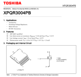
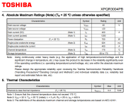
See this new toshiba part.
1696732418709.png
1696732379998.png
I'm curious if it will be fine in a 6 fet configuration. It is only 0.3mOhm. 60A going through two fets (0.6mOhm in series) that's not even 3W continous i^2*r loss at the fet. Burst up to 150-200A that becomes 13.5-24W. No? I only really need to burst to 100A, but for another version I'd like to go up to 150-200A so might as well try to make it happen with 1 fet if I can.

Motor is fine, got that figured out. Making it is another story, but doable.
I was thinking of using 12V for the gate drives.

There are almost no 3V to 12V dc dc step ups (I found one and it has 6 month lead time and costs like $30). However there are a handful of 5V to 12V. And then of course one more step down from 5V to 3.3V. Hence my inclination to go from pack voltage to 5V and then take that 5V to 12V. HOwever, I am not educated as to the power requirements for the gate drive, mcu etc.

I'm trying to keep the inverter rail voltage at pack voltage (1S).
 
Last edited:
Right but how many would I need? Each is 500mA at 12V at 2.5V input voltage. I'm not sure what I need to drive say a 12 FET version using the above toshiba part. Also worth noting the polulu part you linked needs 2.7V to start up, which may or may not be an issue with LFP cells. I can set the controllers to not dip below that I suppose. problem solved.

Also not sure how scalable the polulu solution is.. I eventually may like to put this project into low volume production.
 
Gate drivers need only very small current. I feed a 12 FET TOLL board from a tiny little 5 to 12V boost the size of my fingernail.

Think... number of MOSFETs x gate charge per mos x switches power second. That's your gate driver current. It'll be 12V with tens to low hundreds of mA depending on the FETs and frequency.

Loads of parts available that can do this. Suggest
Battery ->5v
5V->12V for gate drivers
5V->3v3 linear reg for MCU
 
For a proof of concept, couldn't you use any 100A capable ESC with a 12V boost converter to supply the gate drivers and MCU? It wouldn't be an optimized 1S ESC, but it could probably work. Or you could run your solid slot motor on a higher voltage and just let the ESC limit the current to the motor. What is the inductance of your motor?

Check out the MP2 ESC for a good ESC starting point.
Modular, Multi-Platform, 300A ESC
 
Funny you should link that thread, since the OP's post is the last one in it, with this in that post ;)
"I'm looking to make a 1 cell version of the mp2 or suitable alternative."
 
haven't built the motor yet. I built a 7S version before. I don't really want to do a proof of concept ESC, I already did that once crudely. I want to build something reliable that will fit within a 12mm enclosure ideally and be eventually saleable.

MOSFETs x gate charge per mos x switches power second. what do you mean by switches power second. switches per second? Switching frequency?

What do we think about using 3-6 of these direct fet logic level 20V fets in parallel? Then I wouldn't need to step up to 12V. I've soldered these fets before, but 40V versions. Not that difficult to rework.

158nC per fet. 6*20000*158=18960000. Does that mean 0.1896A?
 
Last edited:
Funny you should link that thread, since the OP's post is the last one in it, with this in that post ;)
I don't know if mp2 is the right fit. I rather get even more compact and have assembly house put the fets on. Are direct fets going to be around for a long time?
 
Last edited:
That will depend on how many technologies end up using them. If they don't get widely adopted (or aren't already), then the parts manufacturers won't have a reason to keep making them. ;)
 
perhaps use the ina181a4 current amps with 200x gain and some crazy low resistors...
Would I be better off with the single channel or the quad channel? I kind of want to integrate a low side short circuit protection switch (and to act as solid state power switch for powering on the device) into the inverter. Maybe I could use 3 of the channels for the phases and 1 for the battery. Don't I really only need 2 though for the inverter current sense? I thought that Instaspin would use 3 for better control. Is it the same with vesc and your firmware that 3 is better than 2?

Would it be easier for me or better to start with the MESC kicad files or should I start from scratch to learn kicad properly. I am learning on youtube about the various ways to add libraries and define parts. I saw someone else doing a direct fet vesc somewhere, I wonder if I could just start with that to save some time.
I would start from scratch, but you can copy and paste from various other KiCAD projects schematic's and it carries the data (part numbers etc) with it. No need to be designing your own drivers and MCU pinouts, just drag select, CTRL-C, CTRL-V the blocks.

3 phase current sensing is definitely better than 2, you get common mode rejection. We just added full clarke transform as an option to the VESC code, and it has been default in MESC for years now.

Single or quad opamp makes no difference. It is literally 4 singles in a pack.

Would direct fet logic level 20V parts be worse for some reason?
No, if you can get the appropriate low RDSon parts. I am generally a fan of TOLL just because the shear mass of copper in them gives credibility.

I don't know if mp2 is the right fit. I rather get even more compact and have assembly house put the fets on. Are direct fets going to be around for a long time?
I actually think for the current and voltage you are doing, MP2 with TO220 is simply not the right solution. The leg resistance is going to be significant whereas other packages that is near eliminated. I do agree with thepronghorn that you might be best off getting an off the shelf and hacking it to use 1s even if it is suboptimal though, you are going to be making a hell of an effort for something that most would reasonably think is not destined to be efficient. MP2 is dead easy to hack like this... Personally I encourage you because we have seen 100 different 60-100V MOS ESCs on here, this is something new. Interesting to see what happens at the extreme "I chose current over voltage" end of the spectrum.
 
I do agree with thepronghorn that you mightL be best off getting an off the shelf and hacking it to use 1s even if it is suboptimal though, you are going to be making a hell of an effort for something that most would reasonably think is not destined to be efficient.
I've already done it crudely, don't really want to prove out nothing with a sub par controller. I really don't mind taking the time to do it properly, even if it takes a few spins to get it working. I also would like to try to over build the controller to be able to handle higher current like 200Arms-300Arms range. I would be super happy if I could get bursts in this range, but I'll settle for 100-150Arms too.

I am sure it will be more efficient. Even if it comes just shy, I don't really care, because I've got a simplified battery pack and moved some of the heat away from the motor in the process.

If the motor inductance is less than 1uH, let's say, what caps do I need? How do I size the ceramic caps? How do I place them? Don't ceramic caps have much higher ripple current rating? I'd like to run the motors at 20kHz by the way so that they can't be heard. That impacts the caps doesn't it.
 
Last edited:
Bad idea. Your resistance goes up by 2x if you try to drive them at 3 volts. Take a look at the on resistance vs gate voltage plot.
I see what you mean, however, they would be driven by the 5V rail in my mind, which I didn't clarify earlier.
 
Back
Top