12 FET controller board not working after installing FETs

kZs0lt

100 W
Joined
Dec 5, 2008
Messages
149
Location
Cluj Napoca, Romania
Hi,

I am fairly new to ebike & controllers, but decided to take the hard way and make myself the controller, because it can be fun.
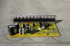
I ordered a 12 FET board from keywin and planning to populate with 4110 FETs. Also got the USB to Serial port cable for programming and a thumb throttle.
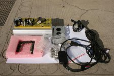
szolgalatok 117b.jpg
This is supposed to be the 600w version with power resistors set for 48 volt, 220, 330 and 680 ohms. Keywin said the LVC is set at 41.5v.
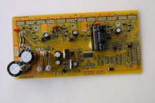
szolgalatok 107b.jpg
View attachment 3
However he forgot to provide the aluminum FET mounting bar.
I tried to get something similar locally but I had no luck, so I made one from the aluminum plate I found around my house:
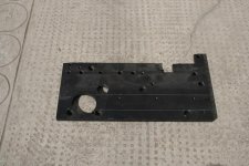
szolgalatok 125b.jpg
Soldered the FETs:
szolgalatok 127b.jpg
And wired the phase, the halls, throttle, battery main and ignition wires.

I have only 2x3s Lipos 4Ah, so I wanted to set the LVC for 20v initially and later get it higher once I get more battery. But I failed to program the board, don't know what I am doing wrong.
I've downloaded the program and installed the .ocx files, installed a USB to serial driver I found, and hit the magic transmit button, touch the board with the connector, and still nothing. What am I doing wrong? What driver are you using and how can I check if my USB adapter is really working?

Next I tried to hook up the controller to the motor. I used a DC current source with ~35v and put 3s lipo in series, so that it gave around 47-48v.
I get a big spark on turning it on, but nothing happens when I hit the throttle. I measured the throttle signal and it was between 0.47-4.3v, the halls from 0v to 5v and the bus voltages look OK. I checked 2 motor phase combinations with every 6 halls combination and no movement from the motor, there is no current on the high current side.
What I am possibly doing wrong? What should I measure to get to the problem, any ideas?

Waiting for your ideas, thanks for the help in advance,
Zsolt
 
do you know if you have 12V and 5V busses?

is there a short in your soldering?

can you see a signal on the hiside of the hiside driver? or the loside driver?

is it possible that keywin left off any other parts like surface mount devices, because of your telling him you wanted it built so and so?
 
I think the bus voltages are ok, between the hall red and black I read a steady 5.03v. If I remember I was reading some 12.x somewhere on the lm317 legs, but I'm not sure where the 12v bus should be read at.
The soldering doesn't look very neat, but there is no short. However some neighboring FETs taht are in groups of two might have the heatsink touching each other. But I suspect these groups are of same phase and same (low/hi) side, working in parallel. Is that still a problem? However I get no spark, and all of the FETs remain very cool. The power resistors get warm.
I don't think that critical surface mount devices are missing, this should be the stock board, I found only 3-4 places where something could be missing, see the pictures.
I don't really know which are the hiside or lowside drivers and where to check for signal, I need your help for identifying that, am willing to learn :) .
I am going to link some closer photos for you soon.
 
go read drbasses 18FET infineon thread. jeremy went through the circuit, and you can decipher from those photos where the high side voltage to the emitter of the pnp transistor is by following the trace in drbasses pictures, above that 510 ohm resistor on the emitter follower circuit which is driven by the logic trace from the microprocessor, and it is the same on your 12 FET board. the high side of the cap and the zener for the hiside circuit.

i am still not certain what you did to the LVC, it is set in R12 and the other resistors to ground, which may be set up differently for different operating voltages, so you may still be disabled by the processor.
 
I came up with the hires photos that might help(click thumbnail to full res):

High resolution pic of the board from top:


Bottom of the board with soldered FETs.


FET thermal pad touching


Possibly missing surface mount devices?
 
dnmun said:
i am still not certain what you did to the LVC, it is set in R12 and the other resistors to ground, which may be set up differently for different operating voltages, so you may still be disabled by the processor.

I was trying to alter the LVC by programming, but didn't succeeded, emailed Keywin and asked for LVC, and he said it was set to 41.5v before he sent it to me, so it should still be 41.5v.
 
that looks like it is used to turn something else off.on somewhere else, nothing missing, imo

the driver drains can touch through the tabs, no problem, just not touching the hiside FETs next to them, they don't.

i am already over my head, stumped. did keywin offer advice?

anybody else have clue?
 
I still didn't got an answer from Keywin, and have no idea what to do.
It might be something simple I fogot to connect, as I am reading the forums a while, but this is first time dealing with controller.
Or it could be worse, and have damaged the chip while trying to program, no idea. But there must be some way to tell what is the problem with.
It didn't run for the first time, but I don't remember if I was trying to program first or only after first hookup.
Could you guys please help and give me suggestions on what to check and how, as I am becoming desperate :(
Knuckles, Geoff, anybody else have clue?
 
did you have power on the processor and the logic lines when you programmed it? i assume so. have you mapped out everywhere you can find signal voltages?

i just started learning about controllers myself, so i am not much help, but more sympathetic than most. seems like you should work. can you measure the input current? when you are powered up, is the hall sensor and motor connected also? can you tell if the hall sensor return has signal at the board?
 
dnmun said:
did you have power on the processor and the logic lines when you programmed it?
I tried programming only by starting the application, hitting the flash button and attaching to the board. I understand that it should work even without FETs. I supposed it uses the USB +5v line. So the battery and ignition was not ON.
dnmun said:
when you are powered up, is the hall sensor and motor connected also? can you tell if the hall sensor return has signal at the board?
Yes, I connected the motor and hall sensors before powering up, and if I rotate the motor backwards (mine is geared freewheeling) and measure hall signals, they are alternating between 0 and 5v all three of them. I remember seeing 0.06A input current. I could't use the mA resolution of my DMM because it jumps high when connecting, and after that it doesn't read accurately. But I'll check that again.
 
knuckles said input current should be 65mA but i assume that is under load, driving the FETs, so it would not be that high while just powering the processor, i would expect. but there should be current leaking out to build up the flyback driver current on the top end. you should be able to find that. like i said, the 18FET infineon thread is sooooo helpful.

keywin will need time to translate stuff you email to him.
 
I can confirm that the no-load current is around 60mA for the 6 FET board. This is pretty much the current taken by the voltage regulators and processor only.

I can also confirm that the controller needs to be disconnected from the external supply when programming, it must be powered up through the separate power connection AFTER pressing the "transmit" button in the software.

The programming sequence I use is this:

1. Load software to PC and change parameters as required. Save the file for future use if required.

2. Connect RX, TX and ground lines from programming unit to controller.

3. Press "transmit" button in software.

4. Connect +5V connection from programming unit to controller +5V connection (on programming header).

5. Ensure that the transmit "progress bar" is moving and the status indicator is showing that programming is complete.

The reasons for failure to programme that I have found are:

- Failing to follow the above sequence, particularly applying power to the controller before sending data from the PC will always cause an error. It is important that the controller "sees" the programming data as it boots up - once booted it cannot see the programming port.

- Failing to ensure that DCD, DSR and CTS on the serial interface are connected to ground.

- Wiring the TX and RX wires the wrong way around. RX on the Infineon is RX on the PC.

Test the PC interface by connecting the RX and TX wires together from the programming unit, opening Hyperterminal in Windows and then try to send characters. They should be echoed and show on the terminal screen. If they don't, then there's a problem in the interface somewhere that needs to be fixed.

Jeremy
 
hi
if you apply power to the fets at a low power with the resistors you have you are liable to blow the fets.
While you are working from 24v to 48v take out the 220 and 330 ohm resistors and put the 330 back where the 220 wire leg was and the 330 wire leg this connects the ignition to the 12 V bus.

Test by just powering the ignition wire to start with, the motor will not turn but you can test to see if the "computer" side of the controller is working properly.

Also check all the fets for short circuits wher there should not be, remember the centre pin of the fets are cconected to the heat sink tab internaly so it is vital that each tab is separated.
Geoff
 
Thanks for your input, and suggestions.

Checked every FET again, no short in the solderings, every FET is isolated from the aluminum bar.
Measured resistance, between phases, it was like 18-19 KOhm. Weird, Steveo said it should be in the MOhm range. GND to Phases 9KOhm again, Vcc to Phases more than my range to accurately measure. These measurement were made while motor was not attached of course.
I have measured the voltages across the 7805 regulator, middle pin to sides, one was 12.2x, the other 5.0x, I suppose those are the bus voltages.
I have tried to supply ~48 and later ~60v to the battery mains and the ignition wire, and the amps drawn were like 58-61 ma for 48v, and 59-63 ma for 60v.
Every hall signal was from 0.0-5.0x volts, usually 2 of them more than 0v. The throttle signal was between 0.5-4.3v. I am pretty sure the throttle is wired correctly, with my wires blue(didn't had black) for GND, white for SP, red for +5v(see photos).
Forgot to check for short through brake line. But it shouldn't have, I didn't touch that.
While on, the power resistors get really hot, the lm 317 and 7805 s get warm, but the FETs are cool, and no sign of heating on the xc846 either.

Tried again programming with the Tx,Dx, gnd attached, and after hitting the transmit button, attached the red +5v too, but nothing. I don't get any error, it's just saying transmit started, and that's all. Like nothing happens. For comm Num 1, 2 and 4, I get "This comm is no use, please try other one!". I installed a driver for USB to serial converter (Prolific brand) and when I plug in, it appears in the System/Hardware/Device manager as comm 5,6,7 or 8 depending on which USB connector I use on the laptop. Could this be a problem? What driver do you use, because mine didn't recognized it automatically? Yes and I tried swapping Tx and Dx, no help. It is possible, that I tried even reversed in my zeal, [gnd, +5v, Tx, Rx] to [Rx, Tx, +5v, gnd]. It is possible, that I've hurt the xc846 doing that? Measured the RX and Tx, and have some 2.7v(or 3.3v?) and 1.7v? while transmitting. I couldn't figure out how to test the converter using windows Hyperterminal , maybe you could expand on this, Jeremy?
However I should concentrate on making the controller work and later I can figure out how to program it :)

How can I test further the "computer" side of the controller?

Zsolt
 
you can see that the phases are tied together through that little resistor in between the driver and flyback FETS. both phases are tied to ground through that resistor, so twice when you go phase to phase. that is the current path for the flyback gate driver pump circuit, to ground, through that resistor.

i think you should get the 'transmit completed' on your laptop when it is done. but i have no clue about that part.

you would expect the power resistor to be hot and the regulators too, everything sounds ok except the micro.
 
zsolt,

I think you may have a problem with the USB serial converter connections. It is important that the serial side of the USB converter have the pins equivalent to the DCD, DCR and CTS serial connections shorted to ground, otherwise you will get the symptom you're seeing. These are pins 1, 6 and 8 on the 9 pin RS232 serial connection.

To test the connection on Hyperterminal, connect the TX and RX connections from the USB to serial converter together. Don't connect the USB to serial converter to anything else. Connect the USB lead and open Hyperterminal and it should automatically detect a valid serial port. Select any baud rate for this test. Anything you type on the keyboard should now appear on the screen (what you are doing here is sending data down the TX lead and back into the RX terminal through the USB to serial converter).

If nothing appears on the screen when you type, then something is wrong with the connection somewhere and the programmer won't work.

The voltages and currents that you've measured sound OK to me, as does the heat from the resistors. My guess is that you still have some sort of inhibit condition that is stopping the controller from working. This may be something miswired, or could possibly be something in the software setup in the controller.

Jeremy
 
Yuppi, I finally succeeded to program the board.

I wasn't talking to the programmer, that was my problem. As I have told, I installed a ("Prolific") USB to serial port converter driver, but didn't realized that it mapped to com7. I tried all four com ports in the program, and except com3, all other ports yielded "This comm is no use, please try other one!", so I thought the USB converter was using that 3rd one, because my laptop has no serial or parallel port. After checking in control panel hardware/device manager, I found that the driver attaches to com5, com6 ... com8 depending on which USB I connect to (having 4 USB connections). But the software can communicate only with com1-com4.
I eventually succeeded to map the converter to com1 from the driver settings, and now works wonderful, it reprograms in 1-2s. I have no idea what is com3 used for.
Many thanks to you guys, especially Methods, who was helping a lot by PM.
I will try to hook up the motor to controller tomorrow, and come back to report whether is going with the reprogrammed controller or not.
I am hoping I will get this working, if the controller can be programmed, it couldn't have serious damage. It might work out to be some silly mistake.

Cheers, Zsolt
 
Tied again to the motor, and still no movement. I am not sure that the hall and phase configuration is right, but I should get at least some wobble, or shaking isn't it? Last time I checked it with 2 different phase connections and every six hall config. No sound. I wired it according to Infineon "standard" with phase colors consistent with hall colors, but I swapped green with yellow on the phase and hall side because I read somewhere that this is the way to wire to a BMC v1. But anyways there is no sign of current passing through the phases.
 
DO YOU HAVE A BMC Mk1?

Geoff
 
geoff57 said:
DO YOU HAVE A BMC Mk1?
Think yes. I got it from jozzer. He said that it was running fine on the bench. I tried it with an RC controller and spins. The hall signals look ok too.
See the pictures here. I have a sticker on it which says is 250w @36v. But they say is more like 400w. Can you confirm this? Don't know what rpm/v but I guess is pretty close to 1. I wouldn't mind beefier phase wires, are these the thicker PUMA ones?
Back to controller issue, do you have any other suggestions?
By the way is this soft or hard start version? it was sent more than 3 weeks ago by Keywin, manufacture date on board is 2008 12 25. For me it's hard to start it for sure :D
 
kZs0lt said:
geoff57 said:
DO YOU HAVE A BMC Mk1?
Think yes. I got it from jozzer. He said that it was running fine on the bench. I tried it with an RC controller and spins. The hall signals look ok too.
See the pictures here. I have a sticker on it which says is 250w @36v. But they say is more like 400w. Can you confirm this? Don't know what rpm/v but I guess is pretty close to 1. I wouldn't mind beefier phase wires, are these the thicker PUMA ones?
Back to controller issue, do you have any other suggestions?
By the way is this soft or hard start version? it was sent more than 3 weeks ago by Keywin, manufacture date on board is 2008 12 25. For me it's hard to start it for sure :D

Im very sorry but there is your problem, we have found the BMC Mk1 and the Infineon are incompatable turning in the drive direction the amps goes off the scale you may have blown somthing in testing to find the correct combination.

There is a glimmer of hope for BMC mk1 Infineon compatability but it is very small.
We have found a reverse combination that works with the motor, now usin X3or DX3 you could get it to go in reverse so getting the wheel to spin the only problem is the reverse speed is max of 70% single speed. I have never tested all of this out as my BMC mk1 is out of action and I am on Pumas now. With all the BMC mk1 variants that there are about it is time a full reverse was fitted to the Infineon this has to be sorted out at the factory not keywin as he is just a middle man. I don't hold out much hope but this is all I can think of.

Geoff
PS it will be soft start yours is pain in neck to start :x
 
geoff57 said:
Im very sorry but there is your problem, we have found the BMC Mk1 and the Infineon are incompatable turning in the drive direction the amps goes off the scale you may have blown somthing in testing to find the correct combination.
Not compatible? :shock:
How could I blow something without noticing any movement, shake, nothing. I get no response from the motor, not a bare sound.
And how can they be incompatible? I understand that switching frequency was a problem for high rpm geared motors, but it's only a 3 phase motor after all. Even my 30a 18v RC controller goes fine with it, without hall sensors, and not pedal first that's true. Can it be worked out with different hall sensor spacing or sequence? Or changing the sensors? I can't believe it won't work with it :cry:
Are you sure this is an mk1 according to pics? Where I can find more information on it?
What controller could work with this motor?

Zsolt
 
Where did you get the throttle from? From Keywin ? Correct type ?

DK
 
Deepkimchi said:
Where did you get the throttle from? From Keywin ? Correct type ?
Yes, from Keywin, it is the 48v thumb throttle with led battery indicators. Is working well, I get 0.5v to 4.3v throttle signal.
 
kZs0lt said:
Not compatible? :shock:
How could I blow something without noticing any movement, shake, nothing. I get no response from the motor, not a bare sound.
And how can they be incompatible? I understand that switching frequency was a problem for high rpm geared motors, but it's only a 3 phase motor after all. Even my 30a 18v RC controller goes fine with it, without hall sensors, and not pedal first that's true. Can it be worked out with different hall sensor spacing or sequence? Or changing the sensors? I can't believe it won't work with it :cry:
Are you sure this is an mk1 according to pics? Where I can find more information on it?
What controller could work with this motor?

Zsolt

hi
yes it is a BMC mk1 mine is identical and I know jozzer and what he sells, the motor will be fine if anything is blown it will be in the controller the infineon has no problem with frequency in high speed motors we can get over 6000 motor rpm with a puma infineon combination, that is not the problem.
As for alternatives there are some out there it depends on the voltage but thees would be ready made and more expensive.

Geoff
 
Back
Top