24s BestechPower BMS Thread

i always measure right on the little solder bumps with my voltmeter since it is easier than going through the pack. also i solder the 9 pin plugs for the cellogs right onto the solder bumps.

but if there is 0V on the 7th cell at the solder bumps then there is something wrong. maybe the adjacent cells allow some kinda resistor divider bridge to fill the gap between but i don't see how unless the shunt transistor is turned on.

if it was the top cell i could see how it would not hit the LVC but in the middle it should always hit the LVC when the sense wire is missing.

also you cannot measure the voltage across the shunt resistors on the D131 because the power daughterboard is on top and in the way.

but the balancing current you wanna measure in charging lead anyway.
 

Attachments

  • DSC01637.JPG
    DSC01637.JPG
    83.2 KB · Views: 2,003
i wonder if the cellogs on the sense wires are creating the resistor divider bridge that is able to deliver enuff current on that channel to keep the LVC signal from switching. i bet the input to the comparator on that channel has a really really high impedance so it would not take much current to spoof the LVC comparator.

you could test that theory by getting it to cut off when the cellogs were removed.

if you don't test it i will eventually. i am gonna go look at the circuit on the inputs on the cellogs. there is a hacking thread here somewhere richard started to allow the circuit current to be taken off the top of the 8S through a linear regulator circuit and then otmar had the idea of using the depletion mode mosfet. which is so elegant.
 
dnmun did you measure voltage across disconnected cells? i measured with and without cellogs connected and the result was the same. both times. there was a fluctuating voltage. i have a voltmeter only so i couldn't follow the reading, but it seems so go up/down between 1 and 5 volts. maybe 0 to 6 volts, but reading lags behind. the other voltages where around 3.2-3.6volts. so nearly at the lowest discharge level.
i repeated charge test with balance wire disconnected and it charged just fine. not very happy :(
please tell me how you do it, and how you managed to let the bms stop charging and discharging when a balance wire got disconnected during dis/charge and if it would start to dis/charge with a balance wire disconnected.
thanks
 
I just read this whole thread because these D131 BMS' are my best option in terms of function and size.
However, there seems to be a lot of failures with these things. I know some failures are from user error, but it appears go beyond that... What's the deal? Are they as unreliable as they seem? I need a rock-solid reliable solution, not something that's going to randomly fail en-route (this is going to be used for my job).

As for the function:
(In case anyone is wondering, this has nothing to do with the 200+ A123 M1 cells that I recently started a thread about... Those are for a different project. I have more A123's from another batch)
It's been stated that you can put any number of cells (up to the max) into these D131 boards and they'll work without any mods, right? I only need a 14S LiFePO4 BMS for right now but was thinking about getting a 16S so I have the expandability for a possible future setup. If it's as easy as leaving the last two connections open then it's a no-brainer.

I wonder if they would be willing to custom program one to balance at 3.45-3.5V. Probably not, but it would be very nice. I'm going to bulk charge (with a CC/CV) and would like for it to be able to stay on well after charging has finished. I've read that 3.45-3.5V is where A123's can float at almost indefinitely, and in addition, my controller is limited to 50V so I don't want to push it beyond that. At 3.6V/cell, 14S is 50.4V. In reality that might work just fine, but I'm pushing it as it is so I don't want to exceed component ratings one bit (it's more than just the caps that are 50V max). 3.5V/cell would give me 49V, which I have tested my controller to, so that would be ideal.
If I'm stuck with 3.6V/cell, then I could set the charger to 49V for regular use, then just balance charge at 51V or so every now and then and bleed off the extra couple volts with a resistor or something if I have to get going hot off the charger (which will probably happen). If I have a little while to wait, I know the cells will bleed some off the top on their own and it'll be no problem. It would be really nice to set it and forget it though. Does anyone know if they'll do that?
 
ALLVLTS said:
I just read this whole thread because these D131 BMS' are my best option in terms of function and size.
However, there seems to be a lot of failures with these things. I know some failures are from user error, but it appears go beyond that... What's the deal? Are they as unreliable as they seem? I need a rock-solid reliable solution, not something that's going to randomly fail en-route (this is going to be used for my job).

As for the function:
(In case anyone is wondering, this has nothing to do with the 200+ A123 M1 cells that I recently started a thread about... Those are for a different project. I have more A123's from another batch)
It's been stated that you can put any number of cells (up to the max) into these D131 boards and they'll work without any mods, right? I only need a 14S LiFePO4 BMS for right now but was thinking about getting a 16S so I have the expandability for a possible future setup. If it's as easy as leaving the last two connections open then it's a no-brainer.

I wonder if they would be willing to custom program one to balance at 3.45-3.5V. Probably not, but it would be very nice. I'm going to bulk charge (with a CC/CV) and would like for it to be able to stay on well after charging has finished. I've read that 3.45-3.5V is where A123's can float at almost indefinitely, and in addition, my controller is limited to 50V so I don't want to push it beyond that. At 3.6V/cell, 14S is 50.4V. In reality that might work just fine, but I'm pushing it as it is so I don't want to exceed component ratings one bit (it's more than just the caps that are 50V max). 3.5V/cell would give me 49V, which I have tested my controller to, so that would be ideal.
If I'm stuck with 3.6V/cell, then I could set the charger to 49V for regular use, then just balance charge at 51V or so every now and then and bleed off the extra couple volts with a resistor or something if I have to get going hot off the charger (which will probably happen). If I have a little while to wait, I know the cells will bleed some off the top on their own and it'll be no problem. It would be really nice to set it and forget it though. Does anyone know if they'll do that?

you don't know what you are talking about. there have not been any failures i have read about.

your need to specify the 3.4V level to balance the lifepo4 indicates you know nothing about the lifepo4 cell either.

your idea of using a resistor to drain down the pack even though it is undercharged is silly.

if you don't wanna use a battery like it is supposed to work why even bother?

what is the point of your post? just to pretend you are superior to the people who designed and built the equipment so you have to specify something abnormal to meet your taste? stuck with 3.6V? like you have a clue as to even why we use 3.60V?
 
There was one of mine failing due to inadequate use :) Dont be so rough we need to bring more sense to people to use proper lithium charging excluding rc stuff :)
On the other note electronics brake and that does not exclude BMS if there are random cases. I dont know why you want to charge lifepo to 3.4, whats wrong with 3.6? If for some reason you still want 3.4 then you need to look at smartbms' es but my thinking is the more futures there are, the more stuff that can go wrong. ...and you pay extra for that
 
Thanks for the much more sensible post. I'm willing to respond to that one. :)
I said 3.5V would be ideal for the specific situation that I explained above, not 3.4V.
3.45 - 3.5 is what I said that I've read can be float at almost indefinitely... I just started to explain why again, but I was just repeating myself so I stopped. I apologize if I wasn't clear enough, but I don't know how to better explain it.


Now... anyone who "knows" LiFePO4 chemistry ( :roll: ), in particular A123, knows that there is very little capacity to be had above 3.45V (let alone 3.5V, which is splitting hairs), and also that charging and/or discharging to less than 100% SOC will increase its life (which isn't something I'm even worried about... it's just a side benefit).
There are many examples of capacity tests on A123's, and here's one more that I just did real quick.


This cell is a sacrificial test cell that I've purposely beat on pretty hard. I experimented with soldering the terminals, and purposely not being quick about it because it's a test cell, I seriously overheated it a few times trying out different soldered connection methods. Then it sat for almost two years with a ~full charge, then I soldered on it again. I then proceeded to do many different cycles at many different charge and discharge currents and voltages. The highest continuous discharge current has been 40A, lowest discharge voltage reaching 0.7V before the charger pulled back all of its current (too-slow reaction when at 40A, I actually had it set to a LVC of 2.0V). Highest charge current 15A, highest voltage 3.9V. Multiple 40A discharges gave an average of 141*F case temperature. I've done more than that to it, but that's the gist of it.

This cell won't reach more than ~2180mAh max anymore. I have several other test cells that I've been much easier on but haven't cycled more than a couple times each since they sat for two years, but they've each reached around 2250mAh. So, this one is an absolutely worst case scenario.
I discharged it to a 2.8V resting voltage (2.0V is recommended cut-off, but there's very little left below 2.8V), then charged it at 3A (which is recommended standard charge current), and charged it to only 3.45V. After that I discharged it at 2C (5.3A, which is roughly what I expect to use per cell continuously in operation) back down to 2.8V.

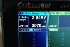
Pictured first is the capacity charging from 2.8V to 3.45V, then the capacity discharging from 3.45V back to 2.8V. Annoyingly, I accidentally hit the stop button early on the discharge when I put my hands down there to take the picture in just a few more moments from then (hence the "STOPS" in the display). I took the pic, then restarted the discharge (the counter starts over) to finish it off at 2.8V, and got 23mAh more, so 2070mAh + 23mAh = 2093 mAh, which is almost exactly equal to the 2089mAh charge, as it should be.
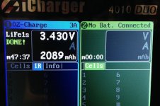
A123 T1 2.8V to 3.45V charge capacity test.jpg

A123 T1 3.45V to 2.8V discharge capacity test (2070 + 23mAh more).jpg

So if we compare that to the full 2300mAh, we get 91% of rated capacity without fully charging or discharging. However, if we take the maximum capacity that this particular cell has now (about 2180mAh from 2.0V to 3.6V), then we get 96% of actual capacity. And that's charging to "only" 3.45V (not even the 3.5V that I said would be 'ideal' in this situation).

I'm certainly far from the most knowledgeable person on this website and I don't claim to be an expert by any means and I could be wrong about anything I say, but I definitely know more than "nothing about the lifepo4 cell".
I really like fechter's signature. It rings very true. :)

I was only asking a couple of honest simple questions, not trying to start anything. I'll go back to my hole for now. Too many words, not enough building.
 
If you want to run the cells in a standby-float condition for long periods of time, then the lower voltage would make sense. Unfortunately, not many of the chips out there go that low. You could use the closest available voltage on the BMS and only rely on it to be a backup secondary protection and use your charger voltage to be the primary. This takes care of everything except balancing. You could try it and see if the cells stay balanced for long periods of float. I've never tried this, but know they do tend to stay in balance if the cells haven't been abused. You could periodically do a balancing charge at a higher voltage where the shunts come on.
 
As fechter said, back off the voltage on the charger to 41.4V for 12S but my thinking is that they will drift. I know mine 20AH do where Panasonic 18650 not so much. You could have a switch on a charger for full 43.8V once a week charge and 41.4V for daily charge. I have not done this mod myself but it should be fairly easy and fechter or dnmun would be more appropriate people on that. Cell man does it for storage charge on hes chargers.
 
Has anyone ever separated the lower module from the top and used the bottom only as a balancer for charging? I'm trying to see if I can salvage one of my bestech 24s bms'. I know that bestech sells the balancer module as the D131A. I was thinking of keeping it connected permanently for when I need to charge the pack and simply monitor discharge with my CA. I have a 21s pack and a bulk 88.2v charger which also has a setting for 90% and 70%. charge.
 
henry will not sell you the balancing board alone. i was able to talk him into sending me one so i could show it so that is why there is a picture of it.

i have separated the top from the bottom and use the bottom as a balancing board as you were asking.

it is mounted under a power board but the connection between the two pcb is separated by cutting all the pins between the two.

i use the power board on that setup as a slave BMS and it is controlled by another D131 which acts as the master board.

this allows me to use two D131 to handle the max current from 44Ah of lipo and the two balance boards provide 350mA of balancing current.

by using one D131 as the master and wiring the two BMS power boards in parallel it will handle more than the 120A peak of one. i have pulled a total of 185A from that pack with the current split equally between the two BMS. 95A from one and 90A from the other.
 
dnmun said:
henry will not sell you the balancing board alone. i was able to talk him into sending me one so i could show it so that is why there is a picture of it.

i have separated the top from the bottom and use the bottom as a balancing board as you were asking.

it is mounted under a power board but the connection between the two pcb is separated by cutting all the pins between the two.

i use the power board on that setup as a slave BMS and it is controlled by another D131 which acts as the master board.

That's good news. So higher cells would discharge while the other cells balance during bulk charging?

I basically did just that cut the pins and removed the top power module which i can no longer trust after trying to take a reading off of it while the meter was still in "amp" mode. :oops: I have spares but thought to try this idea first.
 
tenutso said:
I basically did just that cut the pins and removed the top power module which i can no longer trust after trying to take a reading off of it while the meter was still in "amp" mode. :oops: I have spares but thought to try this idea first.

It's supposed to handle a short without self-destructing, but I never trust that feature. Did it vaporize your meter probes?
 
i guess i do not understand why you removed the power board. it can be tested very easily to determine functionality.

so your meter was damaged by using the ammeter across an active voltage source?

in my case i had a bad shunt transistor on channel 24 of a D131 for lifepo4.

so i used the top power board in combination with the balancing board henry gave me which was for lipo on my lipo pack and i used the power board which had been on the lifepo4 D131 as the slave on the lipo pack.

they are bolted together but not connected and in fact are reversed 180o so the sense wires come out in the right spot which allows me connect the master/slave connections for the charge and discharge mosfet gates easily.

you can still test and even repair the power board you have and then use it with the balance board underneath again by soldering the pins back together on the end. the power board and the balance board do not have to be together and you can connect the two sections with light wires. several of the pins are doubled up as you can tell by examination.
 
fechter said:
tenutso said:
I basically did just that cut the pins and removed the top power module which i can no longer trust after trying to take a reading off of it while the meter was still in "amp" mode. :oops: I have spares but thought to try this idea first.

It's supposed to handle a short without self-destructing, but I never trust that feature. Did it vaporize your meter probes?

It did hold on it's promis to protect from a short.. on the output terminal no problem... as soon as I touched the input terminal it was a spectacular light show. Proble leads, contact pad, solder and wire shot up into the air in a cloud of white light. Boy did it ever throw me off. I'm usually extremely careful. Since then I use a separate meter for reading amp draw. The board is actually ok except for all the charring and missing input contact pad.
 
dnmun said:
i guess i do not understand why you removed the power board. it can be tested very easily to determine functionality.

so your meter was damaged by using the ammeter across an active voltage source?

in my case i had a bad shunt transistor on channel 24 of a D131 for lifepo4.

so i used the top power board in combination with the balancing board henry gave me which was for lipo on my lipo pack and i used the power board which had been on the lifepo4 D131 as the slave on the lipo pack.

they are bolted together but not connected and in fact are reversed 180o so the sense wires come out in the right spot which allows me connect the master/slave connections for the charge and discharge mosfet gates easily.

you can still test and even repair the power board you have and then use it with the balance board underneath again by soldering the pins back together on the end. the power board and the balance board do not have to be together and you can connect the two sections with light wires. several of the pins are doubled up as you can tell by examination.

I'm confident that it would operate after some minor repair (and serious cleaning) as you say and I just might do that one day when I'm bored or find a need to revive it. I bought 4 units for various projects suspecting that I would stumble with one of them at some point. The solder pooled around many of the components and it's such a mess... For now I'll recycle the bottom end and chalk it up to a lesson learned.
 
ok, from what you are saying it was a short through your ammeter from the B+ to one of the soldering pads on the D131? if it was B- then the over current shutoff of the BMS would not cut in.

if you open you voltmeter you will find a high voltage fuse inline on the input terminals and usually soldered to a trace on the little pcb, 250V but only 500mA so if you cannot use that meter now you can open it and either replace the fuse of jumper it with wire, small wire.
 
On another slightly different topic.. I'd like to try one of my spares on an 18s pack which I have. So far I pulled out the extra leads and get a 75v reading through the bms but no current draw and no response from the controller or motor. Evetything is fine when I bypass the BMS. I'm assuming it's in shut off mode because of the blank channels? Is this expected behaviour? I figured since the channels are running squentially it would work. What am I missing?
 
is this a D131? it should not shut off for LVC on the missing channels just because there is no voltage on that channel.

to test the wiring you have to walk the voltmeter probes up the sense wire plug after you connect all the cells to the sense wire cable. i suspect you just have the channels reversed on two adjacent. don't leave the BMS plugged in if that is the case or if you did not already verify the sequence already with the voltmeter.
 
dnmun said:
is this a D131? it should not shut off for LVC on the missing channels just because there is no voltage on that channel.

to test the wiring you have to walk the voltmeter probes up the sense wire plug after you connect all the cells to the sense wire cable. i suspect you just have the channels reversed on two adjacent. don't leave the BMS plugged in if that is the case or if you did not already verify the sequence already with the voltmeter.

It is the D131. Sequence verified while assembling and confirmed before connecting. I will check again and watch closely for a reversed channel. Very possible. Thanks again dnmun.
 
i reversed an entire plug for the top 8 cells on mine. channel 24 was on #17 and channel 17 was on #24. that hurt. it ate the shunt transistor on channel 24 but i was so confident i had wired it up properly that i decided there was something wrong with the BMS, so i bypassed it to allow the pack to charge. but then i noticed that the shunt resistors were all smoking hot, on all channels. never thought i coulda reversed the entire plug.

and it turns out i had used a bad voltmeter to adjust the output voltage on the charger and had charged my 24S lifepo4 to 100V by the time i realized my mistake in bypassing the BMS, which actually was trying to protect me from my own stupidity. 4.21V/cell. !
 
What is the minimum number of cells this board will run on? 4S?? Or perhaps asking it another way, how what cells does the board pull it's power from?
 
tenutso said:
dnmun said:
is this a D131? it should not shut off for LVC on the missing channels just because there is no voltage on that channel.

to test the wiring you have to walk the voltmeter probes up the sense wire plug after you connect all the cells to the sense wire cable. i suspect you just have the channels reversed on two adjacent. don't leave the BMS plugged in if that is the case or if you did not already verify the sequence already with the voltmeter.

It is the D131. Sequence verified while assembling and confirmed before connecting. I will check again and watch closely for a reversed channel. Very possible. Thanks again dnmun.

So I have confirmed that my wiring is accurate. I decided to hook up 24s to see if it works when all banks are full and it does which is good. For some reason 18s is triggering protection with the remaining channels empty. I was searching old threads and read about how you disconnected one of the resistors to close the loop on the remaining channels. Is this required in my case?
 
Back
Top