3KW / 8KW MXUS & Powervelocity 24S2P / 34S6P ?

BobBob said:
Thanks for getting back to me, It sounds as though the chargers you're suggesting are better than some of the ebay rubbish I've come accross. I shouldn't say chinese as being rubbish. Some are good/
I'll do some more reading on your post history - any in particular?
Current and voltage are output via bluetooth so not unmonitored if it's worth doing so. I was planning to be lazy but can look at this if needed
What environmental coefficients should I look at? do you mean values such as temperature?

Dodgy Chinese Bluetooth is not appropriate for the dangerous voltage you're proposing.

Temperature, humidity, input, output, and cat-jumping-on-your-PSU coefficients.

The fundamental problem is that quality commodity chargers are not made for dangerous voltages. Because..well.. it's dangerous, and legit applications for dangerous voltage (commercial EVs) are developed with integrated charging solutions in-house.

Hence the suggestion to split the pack. In fact, my charging interest is currently the logical conclusion: splitting the pack down to individual (parallel) cells, node charging. This would be one way to safely balance charge a high voltage pack, though the sacrifices are considerable, as discussed in that thread.

But worry about your charging last, after you've designed the rest of your system.
 
BobBob said:
That was one of my first questions "is the 4504 the right model of the 3 KV V3 MXUS"
The smartest guys here aren't going to do your homework for you. But yes. Model the higher turn count versions to see why the 4T is incorrect.

BobBob said:
Why should I be able to explain why the Grin Simulator is wrong and why shouldn't I need help and advice?
The motor is bought so the choice is for the battery, IE the quesion is "for a 4T what is the best controller and battery?"
The Simulator isn't wrong; you programmed it wrong. Why are the 4p and 6p packs supplying the same (impossible) battery current?

The motor choice is wrong, because your design flow was wrong. I'm not picking on you -- I suspect that you're smarter than most of the posters here, and can figure this out.

Your design flow was backwards. You picked out a motor first and are trying to bodge a dangerous battery to fix it. You should have (iteratively) modeled your entire system before you bought the wrong motor.

The proper design flow is to define your constraints and goals first. This isn't rocket surgery -- as I've posted, performance ebikes coalesce around very common, almost singular solutions, because they make the most sense:
0) performance controllers max at 90V = 21s. This is already exceeding the safety envelope. This should be your max voltage, so you're not stuck with an exotic hacked controller from a single seller.
1) define your desired no-load speed and work backwards to kV, as described above. You want kV to be as low as possible. Why? What is the relationship between kV and kT?
2) size the controller current for desired torque. You want to have sufficient torque to be control-limited (lifting the front) for as much of the speed range as possible, without burning up the motor. 8kW will burn up a MXUS 3k. How can you get more torque from the same current? See hint above.
3) size your battery current to meet controller current.

Learn from the motor mistake -- don't let it define the rest of your build. You'll spend much more on crazy battery and charger than you would redesigning correctly.
 
fatty said:
BobBob said:
Thanks for getting back to me, It sounds as though the chargers you're suggesting are better than some of the ebay rubbish I've come accross. I shouldn't say chinese as being rubbish. Some are good/
I'll do some more reading on your post history - any in particular?
Current and voltage are output via bluetooth so not unmonitored if it's worth doing so. I was planning to be lazy but can look at this if needed
What environmental coefficients should I look at? Do you mean values such as temperature?

Dodgy Chinese Bluetooth is not appropriate for the dangerous voltage you're proposing.

Temperature, humidity, input, output, and cat-jumping-on-your-PSU coefficients.
I think you mean values such as temperature rather than coefficients such as thermal expansion
What I meant by "what coefficients" was "so what do you want to do about these things?"
if there was a temperature coefficient for example then by defininition it relates to somethign such as charging rate and might mean you slow down charging when it's cold?
fatty said:
The fundamental problem is that quality commodity chargers are not made for dangerous voltages. Because..well.. it's dangerous, and legit applications for dangerous voltage (commercial EVs) are developed with integrated charging solutions in-house.
The last high voltage lithium battery and charger I helped specify/design was for a car sized mobile robot R&D project a year or two ago.
From memory 35KW, three phase 460V AC output from 800V DC or thereabouts - think it was 250S
The two main sources we found for chargers were from UPS suppliers and Solar / power walls, both of which offer modular options.
The customer preferred to leave the charger off the vehicle due to space constraints. There was some discussion around the need for interlocks :)
The battery & system is being built from 18650s by a company who often work on submarines and similar projects
fatty said:
Hence the suggestion to split the pack. In fact, my charging interest is currently the logical conclusion: splitting the pack down to individual (parallel) cells, node charging. This would be one way to safely balance charge a high voltage pack, though the sacrifices are considerable, as discussed in that thread.

But worry about your charging last, after you've designed the rest of your system.
Splitting the pack is still an option, as is buying a commercial Off The Shelf charger. I like the idea of variable voltage and current.
I like to consider everything in parallel (except the cells lol) to make sure I don't miss something that impacts the rest of the design.
The concept of splitting the pack led to the suggestion of a centre tapping with two chargers end to end, removing the centre tapping (or not using it) resulted in the current design which I'll review before implementing my cat and humidity compensation system (a lid)
 
fatty said:
BobBob said:
That was one of my first questions "is the 4504 the right model of the 3 KV V3 MXUS"
The smartest guys here aren't going to do your homework for you. But yes. Model the higher turn count versions to see why the 4T is incorrect.
Thanks.
I did model all of the motors and the 4T appears the best as far as I can tell
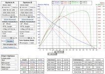
For example with an 87V batt and 70A controller the top speed on the flat is 45 for the 4T rather than 39 for the 5T
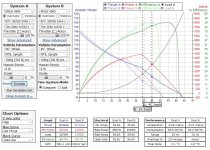
4T Vs 5T.JPG
The 5T peaks at 30 MPH compared to 40 MPH for the 4T.
The 6T is even worse.
At high loads and slow speeds, the 5T is 1% more efficient but it's so marginal as to make no difference as far as I can see
https://ebikes.ca/tools/simulator.html?motor=MX4504&batt=cust_87_.0875_24&cont=cust_70_200_0.03_V&grade=0&axis=mph&throt=100&hp=0&mass=150&bopen=true&cont_b=cust_70_200_0.03_V&motor_b=MX4505&batt_b=cust_87_.0875_24&mass_b=150&hp_b=0&grade_b=0&autothrot_b=false&autothrot=false&throt_b=100&frame=mountain&frame_b=mountain&add=false&blue=Lbs
fatty said:
BobBob said:
Why should I be able to explain why the Grin Simulator is wrong and why shouldn't I need help and advice?
The motor is bought so the choice is for the battery, IE the quesion is "for a 4T what is the best controller and battery?"
The Simulator isn't wrong; you programmed it wrong. Why are the 4p and 6p packs supplying the same (impossible) battery current?
How could I program it wrong? It's a mathematical model of the parts
Grin programmed the simulation. I just selected the parts. Either the resulting answer is correct or it is not
How can the battery current be impossible? I didn't hack the software, so doesn't that mean you are saying that Grin got it wrong?
Confused as to what you mean but the sim seems ok to me
I'll go back and have a look at that in a sec
fatty said:
The motor choice is wrong, because your design flow was wrong. I'm not picking on you -- I suspect that you're smarter than most of the posters here, and can figure this out.
LMFAO: my motor choice is wrong, my (alleged) design flow was wrong and backwards and I picked a dangerous battery to bodge it, 150V is ludicrous, the concept is silly, PowerVelocity provide exotic hacked controllers, the values that the Grin simulator give are impossible and you're not picking on me.
You're helping me, I asked for people to throw rocks at my design. you're spending your time doing so. Thanks
fatty said:
Your design flow was backwards. You picked out a motor first and are trying to bodge a dangerous battery to fix it. You should have (iteratively) modeled your entire system before you bought the wrong motor.
Nope, I did try lots of iterations and lit on the PowerVelocity controller first, Motor second and battery to suit.
I do tend to think of the higher voltage as an advantage though and am debating that with myself. Still like it ATM
fatty said:
The proper design flow is to define your constraints and goals first. This isn't rocket surgery -- as I've posted, performance ebikes coalesce around very common, almost singular solutions, because they make the most sense:
0) performance controllers max at 90V = 21s. This is already exceeding the safety envelope. This should be your max voltage, so you're not stuck with an exotic hacked controller from a single seller.
Right, so PowerVelocity in your opinion is an "exotic hacked controller". That seems a bit harsh, they seem fairly popular here.
You're worried that I won't be able to change suppliers, that makes sense but I could go for a lower performance controller later if this fails
I was originally planning to use the 70A 100V 7Kw version but am tending toward its big brother.
I can always break down the battery and rebuild if I really need to or fix the controller.
fatty said:
1) define your desired no-load speed and work backwards to kV, as described above. You want kV to be as low as possible. Why? What is the relationship between kV and kT?
I'm not even sure I have a desired top speed though around 40 is probably sensible
The power curve, torque accross the speed range under a wide range of loads and battery charge states seems more important.
I therefore tried lots of combinations and the PowerVelocity seemed to win due to higher available voltage and current.
I should try your method but if it tells me I can do 146 Mph I'm not going to believe it :)
fatty said:
2) size the controller current for desired torque. You want to have sufficient torque to be control-limited (lifting the front) for as much of the speed range as possible, without burning up the motor. 8kW will burn up a MXUS 3k. How can you get more torque from the same current? See hint above.
More voltage :)
fatty said:
3) size your battery current to meet controller current.
Yup did that
fatty said:
Learn from the motor mistake -- don't let it define the rest of your build. You'll spend much more on crazy battery and charger than you would redesigning correctly.
Battery can be rebuilt and charger is $130 and adjustable for different voltages if I can be botherd.
BMS might get binned but it's $50 so who cares, Battery may have gone up in flames by then anyway, motor will be toast etc
I think you are suggesting a low Kv, High Kt lower voltage system.
With the battery and controller I'm planning I could always turn the power down
 
Aim: I have had a go at the calculation you suggested but had not yet come to the conclusion you did
Background:
fatty said:
1) define your desired no-load speed and work backwards to kV, as described above. You want kV to be as low as possible. Why? What is the relationship between kV and kT?
2) size the controller current for desired torque. You want to have sufficient torque to be control-limited (lifting the front) for as much of the speed range as possible, without burning up the motor. 8kW will burn up a MXUS 3k. How can you get more torque from the same current? See hint above.
3) size your battery current to meet controller current.

Learn from the motor mistake -- don't let it define the rest of your build. You'll spend much more on crazy battery and charger than you would redesigning correctly.

fatty said:
Pack voltage is designed according to your desired speed. Any more is wasted, and in the case of ludicrous voltages like this, dangerous.
Desired speed in MPH * 1609344mm/mi = mm/h
mm/h * 1hr/60min = mm/m
mm/m / tire circumference = no-load RPM
no-load RPM / 85-90% = load RPM
load RPM / kV = Volts required

Then size controller and then pack current for desired torque.

You need to go back to the drawing board on this. If you got a 3T, your 36s pack on a 26" wheel would give 143MPH :lol:
Method

So taking your suggested calculations above:

Desired speed in Mph, let's say 40 Mph
* 1609344mm/mi = mm/h = 64373760 mm/h
mm/h / 60min/hr = mm/m = 1072896 mm/min
mm/m / tire circumference = no-load RPM = 499 (no, this is the target RPM loaded)
no-load RPM / 85-90% = load RPM 587 - (add 15% - OK)
load RPM / kV = Volts required = 587/9 = 65.2v

I want the system to work well from 3V to 4.15 so I assume I need to use the minimum voltage.

So trying to optimise using your suggested approach of taking the minimum KV:
4503_v2 (3T, 12Kv)
4504_V2 (4T, 9Kv)
4505_V2 (5T, 7.2Kv)
4506_V2 (6T, 6Kv)
I change to the MXUS 4506 being a lower KV
From the calcs above, the voltage is then 97V - too dangerous and also not available
The 5T (4505_V2 5T, 7.2Kv) gives 81.5V so I guess it will work well at cell voltages of 3.9V
Another interpretation of your suggestion might be that it must be lower than the available voltage but as high as possible which would result in the 3T though running at a min voltage of 3.1V / cell seems ok.
Of course if you want more power at lower voltages you need fewer thicker windings for higher current... so the 3T is better but the 4T ok at 63 V

now to test this

Two controllers: PowerVelocity,
15Kw 100V 150A B 300A Ph - 63V on a nearly dead battery
15 Kw 150V 150A 36S 108V also running on emply on the way home

Batteries for comparison, Samsung INr21700 rated 35A with bursts of 45A or sustained 20A
For your suggested maximum 90V system a 21S battery, lets say 5P for a 105 cells 20Ah 0.105 ohm resistance at 63 volts
My suggested 150V 63S3P pack using 108 cells 36S3P 0.3 ohm resistance - a similarly sized pack

Results
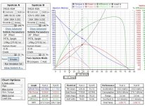
The higher voltage pack is 10 Mph faster and 8% more efficient with alll other components being the same
https://ebikes.ca/tools/simulator.html?motor=MX4504&batt=cust_108_00.3_12&cont=cust_100_300_0.03_V&grade=20&axis=mph&throt=100&hp=0&mass=170&bopen=true&cont_b=cust_150_300_0.03_V&motor_b=MX4504&batt_b=cust_63_0.105_20&mass_b=170&hp_b=0&grade_b=20&autothrot_b=false&autothrot=false&throt_b=100&frame=mountain&frame_b=mountain&add=false&blue=Nm
150V Vs 90v.JPG

Re-running with the 5T it is worse so thinking over why you don't like the 4T motor. 3T is similar to 4T unless you add lots of cells in parallel which puts the cost through the roof.
4T Vs 5T 150 90.JPG

I suspect the problem with the 85-90% RPM calculation is that it doesn't deal with going up a hill through mud with nearly flat batteries.
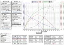
Nope, even with 4X the number of cells and a thousand amp controller your system never gets to 40 MPH, not even on the flat, maybe if we're going downhill? 3T is ok though
1000 Amp.JPG
https://ebikes.ca/tools/simulator.html?motor=MX4504&batt=cust_111.8_00.3_12&cont=cust_100_300_0.03_V&grade=0&axis=mph&throt=100&hp=0&mass=170&bopen=true&cont_b=cust_1000_2500_0.03_V&motor_b=MX4504&batt_b=cust_65.2_0.025_20&mass_b=170&hp_b=0&grade_b=0&autothrot_b=false&autothrot=false&throt_b=100&frame=mountain&frame_b=mountain&add=false&blue=Nm

I still like the Grin simulator -

Do let me know if I stuffed up somewhere as this isn't my preferred approach and I may have misunderstood something
 
BobBob said:
I want the system to work well from 3V to 4.15 so I assume I need to use the minimum voltage to define the pack size?
Well, no -- I would set this as target nominal voltage. Hot off the charger is a little faster, discharged is a little slower. I wouldn't be discharging down to 3.0V anyway -- that's hard on cells, and not needed with a lower voltage, higher capacity pack. But again, this is working backwards from motor to battery -- not optimizing the entire system from scratch.

BobBob said:
So trying to optimise using your suggested approach of taking the minimum KV, I change to the MXUS 4506_V2 (6T, 6Kv)
From the calcs above the voltage is then 97V - too dangerous,
The 5T (4505_V2 5T, 7.2Kv) gives 81.5V so I guess it will work well at cell voltages of 3.9V
Now you're getting it. And which will have greater torque/amp, the 4T or 5T?

BobBob said:
Two controllers: PowerVelocity,
15Kw 100V 150A B 300A Ph - 63V on a nearly dead battery
15 Kw 150V 150A 36S 108V also running on emply on the way home
While I agree with optimizing the energy density of the controller (that is, running max voltage), I'm not sure of your numbers here.
I believe 90V max controllers also use 100V FETs, so there isn't that margin of safety on the 100V PV. So you'd run this at 23s for 96.6V hot, or overvolt with 24s? I think this is where you're getting off track. You should never be running your cells down that low, and thus don't have to design around these unrealistic low voltages, because the cells won't be able to supply such huge current at that SoC anyway -- you'll constantly trip LVC.
Likewise, 150V with no safety factor is 35s for 147V hot, or overvolted with 36s.

BobBob said:
Batteries for comparison, Samsung INr21700 rated 35A with bursts of 45A or sustained 20A
[EDIT] With low speed requirement and high parallel count, I assumed you meant the current -50E. I don't know why you'd sacrifice capacity under your conservative design goals.

BobBob said:
For the 90V system a 21S battery, lets say 5P for a 105 cells 20Ah 0.105 ohm resistance at 63 volts
My suggestion 150V 63S3P pack using 108 cells 36S3P 0.3 ohm resistance - an almost identically sized pack
The higher voltage pack is 10 Mph faster and more efficient with alll other components being the same
The rest of this is back to pie-in-the-sky fantasy. Nobody is arguing that you can't put dangerous voltage through a motor and go faster. But 150V FETs are going to blow eventually on 36s, and you can't dump 8kW through a MXUS 3k. The MXUS is not robust -- look for (or solicit) feedback from poster amberwolf.
Check out the XOFO DD45 as an alternative.

Again, with such a low speed requirement, you don't need such a dangerous, expensive, and exotic solution. If you need dangerous voltage and current to hit 40mph, that should be an indicator that something is wrong.
 
fatty said:
BobBob said:
I want the system to work well from 3V to 4.15 so I assume I need to use the minimum voltage to define the pack size?
Well, no -- I would set this as target nominal voltage. Hot off the charger is a little faster, discharged is a little slower. I wouldn't be discharging down to 3.0V anyway -- that's hard on cells, and not needed with a lower voltage, higher capacity pack. But again, this is working backwards from motor to battery -- not optimizing the entire system from scratch.
I'm not working backward, I'm trying to follow your suggested process, tackling the necessary questions as I go along.
I have to have a target voltage to use your calculation
I'd rather have cells that wear out sooner than lug twice as many around, again that's just personal preference.
fatty said:
BobBob said:
So trying to optimise using your suggested approach of taking the minimum KV, I change to the MXUS 4506_V2 (6T, 6Kv)
From the calcs above the voltage is then 97V - too dangerous,
The 5T (4505_V2 5T, 7.2Kv) gives 81.5V so I guess it will work well at cell voltages of 3.9V
Now you're getting it. And which will have greater torque/amp, the 4T or 5T?
And what drives that same current through a greater number of thinner turns - yup, you got it - higher voltage.
3.9V is not nominal voltage so the 5T won't work, my choice of 4T appears to have been the one your calculation indicates to be the right one all along
fatty said:
BobBob said:
Two controllers: PowerVelocity,
15Kw 100V 150A B 300A Ph - edit this will only have 63V on a nearly dead battery
15 Kw 150V 150A 36S this will have 108V also running on emply on the way home
While I agree with optimizing the energy density of the controller (that is, running max voltage), I'm not sure of your numbers here.
I believe 90V max controllers also use 100V FETs, so there isn't that margin of safety on the 100V PV. So you'd run this at 23s for 96.6V hot, or overvolt with 24s? I think this is where you're getting off track. You should never be running your cells down that low, and thus don't have to design around these unrealistic low voltages, because the cells won't be able to supply such huge current at that SoC anyway -- you'll constantly trip LVC.
Likewise, 150V with no safety factor is 35s for 147V hot, or overvolted with 36s.
90V was 21S or 87V fully charged to be cautious according to PV advice actual volts running at 3V per cell gives 63V available at the end of the day. What I am trying to illustrate is that a system designed for optimum voltage does not work well on low charge cells.
All fo these simulations and calculations are to illustrate that a simple calculation cannot match a simulation IE I don'think that is hte best way, at least for me to understand the interaction of all the variables
My point was that real world use is not a single voltge but you need to design for a range of weights, speeds, charge levels and gradients you are riding up
fatty said:
BobBob said:
Batteries for comparison, Samsung INr21700 rated 35A with bursts of 45A or sustained 20A
[EDIT] With low speed requirement and high parallel count, I assumed you meant the current -50E. I don't know why you'd sacrifice capacity under your conservative design goals.
Each cell can put out a max of around 45A but not for long. I am only using these two battery configurations to illustrate the difference between using you low voltage approach to a high voltage approach with the same number of cells
fatty said:
BobBob said:
For the 90V system a 21S battery, lets say 5P for a 105 cells 20Ah 0.105 ohm resistance at 63 volts
My suggestion 150V 63S3P pack using 108 cells 36S3P 0.3 ohm resistance - an almost identically sized pack
The higher voltage pack is 10 Mph faster and more efficient with alll other components being the same
The rest of this is back to pie-in-the-sky fantasy. Nobody is arguing that you can't put dangerous voltage through a motor and go faster.
The simulations are for going at 20 MPH. We have different opinions about whether 150V is too dangerous. In the UK. 240 is standard for power tools in the rain. I don't disagree I just have a different opinion and am more worried about falling off than the voltage
fatty said:
But 150V FETs are going to blow eventually on 36s, and you can't dump 8kW through a MXUS 3k. The MXUS is not robust -- look for (or solicit) feedback from poster amberwolf.
As I noted before, I've already bought the motor and even your calculation (which I think is misleading) indicates it to be the right one.
fatty said:
Check out the XOFO DD45 as an alternative.
I'll look but I've already bought the MXUS as noted once or twice.
lol, glad you're coming round to my way of thinking, this has almost identical performance to the MXUS :)
I could get 2MPH better top speed but lose a little range and overheat faster due to slightly worse efficiency and it costs more.
It looks pretty good so if the MXUS turns out to be not robust, as you suggest, then this looks a good next option, thanks for the tip.
fatty said:
Again, with such a low speed requirement, you don't need such a dangerous, expensive, and exotic solution. If you need dangerous voltage and current to hit 40mph, that should be an indicator that something is wrong.
My system appears to provide more torque, higher top speed and is more efficient using the same number of cells and the same motor and controller.
I'm happy using 150V to achieve this. I'm not advising anyone else to do so. I work with these sorts of things and it's not for everyone.
I would suggest however that a calcuation that says work out your top speed, take the voltge to achieve this unladen then add 10% to the voltage and you're all good is not up to the job I'm afraid.
What if you're going up a hill?
 
BobBob said:
What if you're going up a hill?

Indeed: this misunderstanding sums up my argument pretty well.
If you're going to play with dangerous voltage, you should know this has nothing to do voltage.
Anyway, forget it. Just be careful with your 20-40mph, 150V 8kW MUXS 3k. Let us know how it turns out.
 
fatty said:
BobBob said:
What if you're going up a hill?
Indeed: this misunderstanding sums up my argument pretty well.
If you're going to play with dangerous voltage, you should know this has nothing to do voltage.
Anyway, forget it. Just be careful with your 20-40mph, 150V 8kW MUXS 3k. Let us know how it turns out.
Your calculation means "take the target speed unladen, then add 10-15% to the voltage"
It does not take the torque requirement into account, that was my point.

I'm not sure what arguement you mean, maybe you implied something else, if so I missed it. I spent a while looking.

Yes I'll be careful playing with 150V.
Some think guns, motorbikes, COVID, chainsaws, cave diving or skiing are too dangerous. Opinions vary on risk. Personal choice.

Yeah, I expect I've misunderstood some of the stuff you said - it's often difficult to know whether someone has a smile on their face as they type, so, thanks for throwing rocks at my ebike design. It's been a tough week and this has been a welcome distraction.

WOT; the 150V version is around 9Kw and 60 + Mph for about 1.5 minutes when it tears it's own wheel off and bursts into flames :twisted: .
 
BobBob said:
Your calculation means "take the target speed unladen, then add 10% to the voltage"
It does not take the torque requirement into account, that was my point.
And my point was that voltage has nothing to do with hills or torque. I'm not saying everyone has to understand (that) fundamental before building their first ebike, but you should understand fundamentals before you play with dangerous high voltage.

I wasn't throwing rocks at your design, but rather your process. This thread almost mirrored the other 8kW thread that was posted at the same time, and indeed like half of the other threads on here that aren't grounded in fundamentals and refusal to learn them. It's a monumental waste of both of our time.
 
fatty said:
BobBob said:
Your calculation means "take the target speed unladen, then add 10% to the voltage"
It does not take the torque requirement into account, that was my point.
And my point was that voltage has nothing to do with hills or torque.
Nope - what you said, was "Without the motor kV, this is all mental masturbation" followed by a calculation that suggested taking the voltage required for unloaded RPM at target speed and just adding 10% volts and unlimited current.
You also said that the 3T version (which would be pretty good) would do 146 MPH and i should go back to the drawing board.
You were clearly not considering torque or any other system parameters.
Voltage drives current which has everything to do with hills and torque. Motor choice converts that current into torque.
That's why your calculation, following the comment above comes up with a 37 mph bike and mine goes 50, using the same components.
https://ebikes.ca/tools/simulator.html?motor=MX4504&batt=cust_111.8_00.3_12&cont=cust_100_300_0.03_V&grade=0&axis=mph&throt=100&hp=0&mass=170&bopen=true&cont_b=cust_150_300_0.03_V&motor_b=MX4504&batt_b=cust_65.2_0.025_20&mass_b=170&hp_b=0&grade_b=0&autothrot_b=false&autothrot=false&throt_b=100&frame=mountain&frame_b=mountain&add=false&blue=Nm
fatty said:
I'm not saying everyone has to understand (that) fundamental before building their first ebike, but you should understand fundamentals before you play with dangerous high voltage.
The dangers of high voltage are a completely different subject. I'm an engineer, familiar with risks and it's only me I'm risking.
fatty said:
I wasn't throwing rocks at your design, but rather your process.
I asked you to throw rocks at my design - thank you.
You don't know my process. Lots of simulations plus peer review and see what sticks isn't a bad approach to start though.
fatty said:
This thread almost mirrored the other 8kW thread that was posted at the same time, and indeed like half of the other threads on here that aren't grounded in fundamentals and refusal to learn them.
He posted once and never came back. You posted your equation that ignores torque without explanation. You also posted to say his choice of batteries was bad but Dogman Dan said it was a good / safe choice.
Have you thought about delivery? We're all human and when someone says your idea is silly and you should go do your homework, this is all mental masturbation, or your design isn't gounded in the fundamentals there is perhaps less inclination to take your words of wisdom on board. It also helps if you're right.
I'm here to learn, despite some differences of opinion, I have found the references you sent useful. I'm learning the ebike basics - thanks
fatty said:
It's a monumental waste of both of our time.
Sorry you feel that way.
For me, the bike is a toy, and a hobby and this is some freindly banter, you don't have to reply. I reserve the right to.
Some of your comments have seemed a bit abrasive and I've reacted with somewhat pointed humour, and graphs to illustrate where I believe you got something wrong.
I put my design out there and asked the world to throw rocks at it, it seems to be still standing.
Thanks for taking your time to do so. Science is about challenging things so it seems only fair i'm allowed to chuck the occasional rock back.
Keep a grin on your face, this is for fun and we might change the world :)
 
Ha - my design is FINE - almost the same voltage, controller power and exactly the same motor!
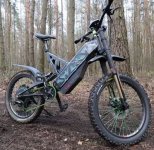
Found a youtube on the Cyklonebike Viper yesterday. Pictured below. https://www.youtube.com/watch?v=qDmYSk2tjNs&ab_channel=WrongWay%21
In my head, my concept is a lot like it (yeah, I know, tell me I'm dreaming)
Cyklonebike Viper.JPG

Viper - - - My hillbilly version

200A - - - 300A max per phase
100V - - - 115V nominal (135V 32S max to allow some headroom for the 150V controller)
8KW - - - Same as I put in the title
Simliar battery capacity to my 32S4P concept
Their frame is bespoke, heavier and they have a 200mm suspension travel instead of 150/170 but I expect to do some welding and machining as I break things. their frame geometry will be slacker and better for higher speed, everything is designed for it, but I'll be 10 Kg lighter and can chuck mine in the back of my car fairly easily

and they chose the same 4T version of the MXUS 3KW motor
 
Weird Lacing:
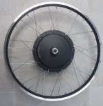
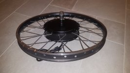
The wheel and motor just turned up.
The rim looks decent, double skin, 42mm wide, 34 inside to the bead
10Ga spokes ping at similar notes and wheel runs true, some spokes are slightly bent, the rim holes weren't angled but it seems good overall, however:

Different alternate spokes
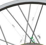
The thing that surprised me is that it has two sizes of spokes. Alternating spokes are different lengths so at different angles.
The shorter spokes will accellerate the wheel and measure 137mm / 5.4" from hub to nipple whereas the ones slowing the wheel measure 152mm / 6"
They seem to be different and the wrong way round. The more slopey ones should be pulling the wheel round if they are going to be uneven.

Thinking
Having said that, all the long ones point in the same direction. They will stretch a bit more when I hit a bump, partly due to being longer (proportional to the length 11% difference) and partly due to the less radial angle.
This will mean that the hub rotates slightly with respect to the rim when it hits a bump but I don't think that matters.
The forces on the rim will also be uneven, the ones pulling one way will be more angled than the others so the deflection of the rim due to the spokes will be uneven but I'm guessing less than a mm / 1/16" so maybe it doesn't matter? maybe I should turn them all round so at least the theoretical 300Nm torque is on the most angled spokes as that is around 250 Kg at the edge of the hub.

Homework
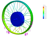
Gonna try a simple single body FEA on solidworks - helps me picture all the stresses in the wheel as I'm relatively new to this.
I'm going to have to start reading about lacing I guess, as I've been lazy and bought one ready made rather than working out how to do it myself.

All good fun and it's a stonking rim and spokes so hopefully makes up for the weird build
Top View.jpgAngled.jpg
 
Hmmm
Sometimes I think my computer is taking the piss (red is 20 microns / 0.8 thou displacement)
Displacement Static 150Kg.PNG
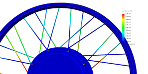
Pretty colours. The thickness of spokes plus inability of solid model to show pivoting spokes isn't much use
150 Static 2.PNG
Taking the measured difference in spoke length within the wheel geometry (could have done this with a paper and pencil):
2D basic force triangles: all the clockwise spokes are at the same angle. Ditto all the CCW so 2 angles are all we need.
The torque CW must equal the force CCW when stationary.
Making the torque values equal, the ratio of radial forces is 1:1.8 so half the spokes are only taking 35% of the load and the other half are taking 65%.
Get one right and the other will be too tight (likely to break the rim) or too loose - likely to loosen and generating more cyclic loading and shock around the spoke hole
Spoke Stress.png
 
BobBob said:
Nope - what you said, was "Without the motor kV, this is all mental masturbation"
Definitively correct. Not knowing kV is flying blind.

BobBob said:
followed by a calculation that suggested taking the voltage required for unloaded RPM at target speed and just adding 10% volts and unlimited current.
No, I offered this approach since you bought a motor without knowing the kV or modeling the rest of the system. I said nothing of unlimited current -- quite the opposite...

BobBob said:
You also said that the 3T version (which would be pretty good) would do 146 MPH
Unloaded.

BobBob said:
You were clearly not considering torque or any other system parameters.
Voltage drives current which has everything to do with hills and torque. Motor choice converts that current into torque.
Again, quite the opposite -- kV and kT are direct inverses. Your motor spinning at 146MPH unloaded necessarily produces less torque than a lower kV, higher kT motor. Of course, you can compensate by dumping dangerous volts and amps into the motor --until it burns up, which your MXUS will do at 8kW-- but that doesn't make it a good idea.

BobBob said:
That's why your calculation, following the comment above comes up with a 37 mph bike and mine goes 50, using the same components.
You said your target speed was 20-40MPH. What good is 50 when it costs you kT to get there?
Look, I don't know what kind of SDE you're trying to compensate for here, but we're speaking completely different languages. You're clearly smart enough to get this, but instead of designing around nominal pack voltage, you're designing around a fully-discharged 3.0 or 3.1V/cell voltage, which is incorrect since cells at such a low SoC won't be able to supply the silly current you're fantasizing about anyway. Keep overcompensating with that 150V 8kW -- but let's put each other on ignore so we don't waste any more time.
 
Nonsense, I quoted the simulation's I'd done in my first post - you're just being rude because I pointed out you gave bad advice.
All the simulations show that the original plan was pretty good, I'd done a few checks before posting first
I've covered the rest before
I don't have a target top speed. 40 was a hypothetical example when discussing your calculation.
Spare capacity on voltage and on current means I have a bit spare when capacity drops. Still working on battery
I want to have spare power mid range at the expense of best efficiency top end, makes sense to me.
The Cyklonebike Viper also has a MXUS 3K 4T running at 8KW in fact it appears to be almost the same spec so I'm pretty happy with what I came up with, Yes I know how fast it overheats
And, last but not least, I'm riding my ebike home after a long day and want to know how it will perform at around 3V and the best cell configuration when it's nearly dead.
Not completely dead
So by definition it's working and it's at 3V, it's not resting voltage, the controller and BMS can't see resting voltage when riding
It seems a sensible design goal to ensure that the system works in a worst case state
I had missed, however that my simulations were using resting voltage, re-checked an the higher voltage provides better performance. Thanks for the heads up
Feel free to come back or to ignore me
 
Are you really using 10ga spokes? If so, I'm genuinely curious why? From what I have been seeing, thinner spokes (13, 14ga) are generally preferable for maintaining good wheel reliability and performance.
 
99t4 said:
Are you really using 10ga spokes? If so, I'm genuinely curious why? From what I have been seeing, thinner spokes (13, 14ga) are generally preferable for maintaining good wheel reliability and performance.
My best / current understanding is that you need a rim that is proportinally stronger and you need to tighten the spokes to stretch them about the same amount, IE proportional to the additional strength.

Why did I get them? I bought the wheel fully built from an ebayer https://www.ebay.co.uk/itm/133711024589?ViewItem=&item=133711024589 and he offers it with 10 Ga spokes. He didn't offer different spoke options and I didn't ask at the time, as I didn't give it much thought beyond thicker is stronger.

Since then I've read that the springiness of thinner spokes helps reduce the shock and potential damage to the rim. I don't think this will make much difference if installed correctly
From the analysis I did, the amount of movement on the 10 Ga was of the order of 10-20 microns (0.4 Thou) though the model was not mechanically complicated so the answer will not be very accurate, I'd expect it to be less but of that order of magnitude.

With spokes that are (3.15*3.15mm)/(2*2mm) or 9.9/4 or aboiut 2.5 x the cross section the movement on the 14 Ga is around 25 microns / 1 thou or about half the thickness of a human hair with 750KG or 1,650 lb weight (5G) on it.
When compared to the amount of compression of the tyre, this is tiny. 1/1000
Of course if you hit a curb, the rim is much more likely to give way if you have a stronger spoke that might snap instead.

I would expect that putting shorter thicker spokes would be a little more likely to break a rim, putting a hub motor in would be much more likely to break it and the reduced cross patterns would also make things worse as they generate a mechanical advantage as they deflect

With a robust enough rim, I would hope that the thicker spokes would work ok, they do for motorbikes but the rest of the system has to match the spoke in strength
The rim that came with the wheel is a 42mm wide, double skinned, fairly robust affair so, I'm hoping, designed for the additional hub weight and the spoke size.

Seeing as it apparently turned up laced back to front I'm less convinced today.

Went and did 10 minutes reading:

OK, stuff I already knew - the elbow needs to be supported in the hub so that it doesn't bend and flex, a thicker spoke may also be designed for a thicker lip on the hub so not be sufficiently supported by a thinner one.

Bending may strain the spoke, or rim. Tensioning a shorter spoke is more tricky (regardless of thickness) there will be fewer suppliers of decent qualify 10Ga so lots of potential problems but I haven't seen a good fundamental reason they shouldn't be better, so long as the rest of the system is also beefed up.

My guess might be that for stronger spokes you need stronger rims so you can give them more tension so they are stretched about the same amount and most rims are not designed for 10 Ga spokes.

Feedback appreciated, I'm just thinking through this out loud and have probably missed something
 
Thanks Chalo https://endless-sphere.com/forums/viewtopic.php?f=51&t=111528#p1653334
Need to work out how strong the rim is somehow
 
So a bit of an update and a few questions:

Re-lacing the wheel - 4 bike shops were contacted, dropped if off but had it returned because their jig wouldn't fit the M16 axle, contaced another who agreed then changed his mind and referred me to a sixth who reckon that the MXUS hub flange and the double skin rim sold with it are not strong enough for a 10 GA but should suit 12 Ga so have changed to butted 10/12GA to maintain the flange hole size fit. Got it back and it looks a lot better than previous.

Decided on the Sevcon Dragon8 controller.
It says it's rated at 96v nominal and 140v peak (145v non operating) and I'm wondering how far this can be half sensibly be pushed.
I'd prefer to keep charging to 4.1V per cell and I read somewhere that leaving 10V headroom for inductive spikes was sensible so a max charge of 4.1V per cell gives a 31S or 32S giving 132.2V or 8.8V headroom.
An interpretation of the 145V non operating might be that Sevcon is allowing 5V for inductive spikes.
The difficulty is that inductive spikes are a product of the size of the capacitor in the controller, the induction in the inlet wiring, current flowing and how it's switched.
Of course the induction is worst when a high current is flowing in which case the voltage would drop to around 111V at peak amperage.
This means that a smaller (fewer parallel cell) battery with higher resistance could probably be safely run at a higher maximum unloaded voltage as the operating voltage would be lower.
Anyone with any thoughts on max Series cells

Got myself 100 Molicel INR21700-P42A which are rated at 45A giving a theoretical max of 135A for a 3P configuraton.
I can just about fit 96 in the triangle https://e4bike.ru/page/battery-shape-configurator?c=42110203203667178669400596458178041 and I think that as the Sevcon Dragon8 can handle 400A for a burst and I can only supply 135A, and it will be at 111V if so; the inductive load will be far lower than the max the Dragon8 can handle

Awaiting the Sevcon tech help response, other opinions also of interest
 
Back
Top