4110 vs 4115 FETs in a Xie Chang controller better? w/PICS

zombiess

10 MW
Joined
Jan 31, 2011
Messages
3,048
Location
Oklahoma City
I see this posted quite frequently but my personal experience so far has not shown any real difference in real world use (when both are built properly). In what I have read, the number one reason I have seen is the fact that the IRFB4110 FETs have a lower RDSon vs the IRFB4115. This is an absolute fact and there is no disputing it but I feel it’s important to discuss the other characteristics of the FETs to get a better picture.

I'm not mentioning operating voltage in this discussion because I'm trying to make a 1:1 comparison. When comparing them I would not exceed 100V on either FET.

Let me first post my own justification for choosing the IRFB4115 FETs in the controllers I personally build and use. Hopefully my thinking is not flawed.

1. Both of these FETs are TO-220 package which limits maximum current to around 75A which is where I choose to limit my phase amps for reliability. Because a 12 FET has two FETs in parallel I limit it to 150A phase max, 24 FET (four FETs in parallel) 300A max, etc.
2. Both will suffer similar switching losses regardless of RDSon
Volts * Switching Freq / 2 * (Turn On Time + Turn Off Time) * Phase Amps
3. RDSon makes up just a small part of overall losses, switching and diode losses are usually higher in most operating modes with diode losses especially high below 50% duty cycle.
4. The Xie Chang controllers have weak gate drivers and the IRFB4115’s are easier to drive into over saturation. IRFB4115 has a Qg of 77nC vs the IRFB4110’s QG of 150nC.

Most people on this site have seen people complaining of FET failures on controllers, sometimes it’s a single high or low side FET that that blows, other times multiple FETs in the high or low side. Reading back through several posts and info on controllers which use IRFB4115’s it is often recommended to run much lower amperage than the same controller using IRFB4110’s. I have a theory as to why it seems the IRFB4115 controllers often don’t handle similar currents as their IRFB4110 counterparts. I believe it is caused by not properly Miller Plateau matching the FETs which are paralleled together and secondarily not having enough low ESR bypass capacitance across the rails by each phase.

I arrived at the paralleling theory by individually measuring 300 IRFB4110 and 300 IRFB4115 FETs. Out of each king at least 250 of each kind were from the same batch with others coming from various other batches. The matching was done by holding the gate voltage below the miller plateau and calculating the resistance between drain and source. I noticed that the majority of the IRFB4110 FETs were pretty close to each other when all held to the same Vgs. There were some outliers that exhibited a resistance up to 100x higher than the median value, but the occurrence of these was infrequent with only around 20 out of the 300 being 50-100X higher than the most common values. The IRFB4115 FETs on the other hand had a much higher diversity of values with more even distribution into each group and less low/high value outliers.

I did not make not of exact numbers but when I grouped them into piles they went something like this:
I am using ohm values to estimate what I found when holding Vgs at a constant voltage and change the FETs.

IRFB4110 FETs
10 - 10 ohms
10 – 20 ohms
30 – 30 ohms
30 – 40 ohms
50 – 50 ohms
50 – 60 ohms
50 – 70 ohms
20 – 80 ohms
10 – 90 ohms
10 – 100 ohms
10 – 100 to 200 ohms
20 – 210 to 5000 ohms

IRFB4115 FETs
05 – 20 ohms
05 - 30 ohms
10 – 40 ohms
10 – 50 ohms
10 – 60 ohms
10 – 70 ohms
10 – 80 ohms
10 – 90 ohms
10 – 100 ohms
10 – 110 ohms
10 - 120 ohms
20 – 130 ohms
20 – 140 ohms
20 – 150 ohms
20 – 160 ohms
20 – 170 ohms
10 – 180 ohms
10 – 190 ohms
10 – 200 ohms
20 – 210 to 300 ohms
20 – 310 to 500 ohms
10 – 510 to 1500 ohms

While these numbers are not exact, they illustrate why matching paralleled FETs is important on the IRFB4115’s. If you are paralleling 4 FETs and select them at random your chances of getting FETs which are not close in conductance is pretty high which results in unequal turn on and one or two FETs having to take the full current before the other FETs turn on and share the load. The chances of getting closely matched IRFB4110’s are much better which is one reason why I believe they suffer less failures at higher currents.
I only know of myself matching FETs for use in my personal ebike controllers so my sample size is miniscule, but I have had good success with the IRFB4115’s.

I just completed a 24 FET IRFB4115 controller with a temp sensor on a switched FET bank and will build another using IRFB4110 FET with a temp sensor so I can hopefully make some comparisons in operating temp. I’d also like to measure the turn on times between them to see if one switches on/off faster than the other due to the difference in their gate charges.
 
Interesting. Thanks for posting the info zombiess.

I ran an 18 FET 4115 equipped controller in my Bomber for 18 months (and still running strong) 12kW peaks (100A), not a problem. Never lost a FET. Cant say the same about my 4110 equipped controllers though.
 
Kepler said:
Interesting. Thanks for posting the info zombiess.

I ran an 18 FET 4115 equipped controller in my Bomber for 18 months (and still running strong) 12kW peaks (100A), not a problem. Never lost a FET. Cant say the same about my 4110 equipped controllers though.

I have an 18 FET 4115 controller I modded that has been programmed for 100A battery, 125A phase. I ran 12kW for a while but turned it down to improve control ability, 20+ mph power wheelies are fun, except when you are not expecting them.

Another interesting bit of info is my temp sensor sitting directly on the FET rarely went over 75C unless I was doing back to back high speed runs from a dead stop at over 10kW.
 
Its nice to see you back in the game Zombies :)
 
I would say switching losses are not be the same, because they both have different amount of gate charge needs. This will influence the turn ON/OFF time.
 
And with the really hi resistance gate resistors the time with change a lot with different gate charge values.
 
Njay said:
I would say switching losses are not be the same, because they both have different amount of gate charge needs. This will influence the turn ON/OFF time.

This is what I was thinking as well. I just went back and looked at my scope pictures from when I measured the gate drive on the high side of my EB236, 36 FET controller I built with IRFB4115's. It takes 2.5uS to reach the miller plateau @5V which is where it's effectively in full conduction. I'm planning to make the same measurements on the EB224 24 FET controllers I'm currently building to see what they look like on both IRFB4110 and IRFB4115's. The IRFB4110's hit the plateau around 4V if I remember correctly.

What about thoughts on over all power handling capability due to the TO-220 package? I feel 50A continuous, 75A for 30sec and probably 100A for a short 10 sec burst is realistic. This is of course assuming the case temp of the FET is kept under 80c.
 
There's AN-1140 from IR about maximum continuous package current, but I feel they go round and round and in the end give no usable numbers, only an algorithm. I still can't wrap my head around that AN. They have a table for the "ultimate current" for the several packages, which I think is the "package limited" rating we see in datasheets, and then say that "with no attention to (package) lead thermal management, the recommended current for all of the packages above is 75A.". The problem is that the table refers to values obtained from tests where they use some "exotic" cooling method ("full immersion of parts in a nucleated-boiling inert fluid.").

I saw some pics of an open sevcon and I counted the number of MOSFETs (TO-220) they had; if I recall, dividing the current rating of the controller by the (total) number of FETs gave 32A per MOSFET. I don't remember if I used only 1/3 of the FETs for the calculation.

I think it's irrelevant at what voltage they reach the plateau, since time is what matters here.
 
Njay said:
I saw some pics of an open sevcon and I counted the number of MOSFETs (TO-220) they had; if I recall, dividing the current rating of the controller by the (total) number of FETs gave 32A per MOSFET. I don't remember if I used only 1/3 of the FETs for the calculation.

I think it's irrelevant at what voltage they reach the plateau, since time is what matters here.

That sounds like a reasonable rating for Sevcon because it's for continuous use I believe, overhead is good. I did find one post on a forum somewhere where a person tested the legs of a TO-220 FET due to the spec sheets and found that it melted at 150A. I keep finding the 75A number different locations so that is what I'm going to stick with.

I brought up the voltage for mainly for my own records in this thread so I don't have to reference my old pictures. It's also helpful for anyone reading this who is not familiar that different FET's have different turn on voltages.
 
POST EDITED: Sorry for commenting.
 
Arlo1 said:
Zombies You are doing it right. If you want to run higher numbers you need a more accurate controller. These Controllers just guess at phase amps and this causes them to over shoot a lot of the time with a conservative number like 75 amps programed for phase amps you will likely still have times when the controller lets bigger numbers flow without meaning to. You might be surprised to find the true phase amp numbers. I am going to build a phase amp sensor for testing things like this. Farfel ( I think it was) found that the torque was lower with a sevcon vs a china controller I think that they were the same phase amps programed but the sevcon did not make mistakes so this will allow it to live :)

While what you are saying is true, it's irrelevant to this discussion which is about comparing the FET's and their current handling capabilities based on the package limit and the belief that IRFB4110 FET's are superior to IRFB4115's.
 
zombiess said:
Njay said:
I saw some pics of an open sevcon and I counted the number of MOSFETs (TO-220) they had; if I recall, dividing the current rating of the controller by the (total) number of FETs gave 32A per MOSFET. I don't remember if I used only 1/3 of the FETs for the calculation.

I think it's irrelevant at what voltage they reach the plateau, since time is what matters here.

That sounds like a reasonable rating for Sevcon because it's for continuous use I believe, overhead is good. I did find one post on a forum somewhere where a person tested the legs of a TO-220 FET due to the spec sheets and found that it melted at 150A. I keep finding the 75A number different locations so that is what I'm going to stick with.

I brought up the voltage for mainly for my own records in this thread so I don't have to reference my old pictures. It's also helpful for anyone reading this who is not familiar that different FET's have different turn on voltages.
OK so my last post has nothing to do with this?
 
I have no hands-on experience I can hold-on to to make more concrete comments about this. You know how to calculate heat dissipated at the MOSFET, and with that info and the heatsink thermal mass and thermal resistance one can estimate thermal behavior. Problem is that you probably don't have specs for the heatsink. Same for the package leads; shouldn't be hard to calculate the heat dissipated there using the lead geometry and current, but then we don't know the thermal mass and resistance for lead-air (IR says the thermal resistance lead-silicon is so much higher than lead-PCB that basically all heat generated in the lead goes to the PCB).

Relying on previous experiences by others isn't always a reliable foundation. When you say that a guy tested a lead and it fused at 150A, it really lacks "context" like thermal history, how much time did it took, how long was the piece of lead used, was it soldered on a PCB, how much PCB copper/solder there was, etc etc.
 
Arlo1 said:
zombiess said:
Njay said:
I saw some pics of an open sevcon and I counted the number of MOSFETs (TO-220) they had; if I recall, dividing the current rating of the controller by the (total) number of FETs gave 32A per MOSFET. I don't remember if I used only 1/3 of the FETs for the calculation.

I think it's irrelevant at what voltage they reach the plateau, since time is what matters here.

That sounds like a reasonable rating for Sevcon because it's for continuous use I believe, overhead is good. I did find one post on a forum somewhere where a person tested the legs of a TO-220 FET due to the spec sheets and found that it melted at 150A. I keep finding the 75A number different locations so that is what I'm going to stick with.

I brought up the voltage for mainly for my own records in this thread so I don't have to reference my old pictures. It's also helpful for anyone reading this who is not familiar that different FET's have different turn on voltages.
OK so my last post has nothing to do with this?

Arlo1, I hope you didn't take offense at my post because it wasn't meant that way. I'm trying to keep this thread mainly about the difference/similarities of the IRFB4110 and IRFB4115 FET's and how much current they are able to handle in a controller. Secondarily I brought up the Xie Chang controllers because they have a very weak drive and I have a theory that the IRFB4115's are actually easier to drive than the IRFB4110's. The comments I made about the sevcon were directly related to how much each FET has to current share vs it's rating.

I'm not buying into the data sheet koolaid and I've run the loss calculations and made measurements on the gate drivers in regards to the Xie Chang boards. I am theorizing that on ES people mistakenly praise the IRFB4110 and shun the IRFB4115 all based on the RDSon value and experience. I'm attempting to debunk this with what I've found in my own testing and I'm pretty sure the #1 problem why IRFB4115 controllers tend to pop at lower current is because the paralleled FETs are not matched for the same turn on time.
 
Bumping this back up now that I have some scope pics to post. Thought some might find this interesting.

Controllers are built the same, programmed to same settings, run at same voltage, same load, same throttle, both measured on high side FET's which is the side that gets PWM, only change is FET's.

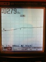
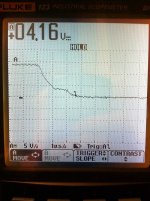
IRFB4110:

Turn on:
2.5uS to get to Miller Plateau
2.0uS spent on Miller Plateau
3.0uS to turn off

Turn On:
4110-1.jpg

Turn Off:
4110-4.jpg

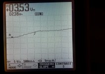
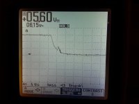
IRFB4115:

Turn on:
2.0uS to get to Miller Plateau
1.5uS spent on Miller Plateau
1.7uS to turn off

Turn On:
4115-1.jpg

Turn Off:
4115-2.jpg

24 FET controller Estimated switching losses based on above numbers:
15.9khz, 50% Duty Cycle, 100V, 225A Phase

IRFB4110
983.8W Switching
51.0W Resistive
146.3W Diode
1181.0W Total Losses

IRFB4115
661.8W Switching
134.3W Resistive
146.3W Diode
972.7W Total Losses
 
Did the 4110s get hotter?

What formulas did you use? I get 1342W for the 4110 and 930W for the 4115 switching losses.
 
Njay said:
Did the 4110s get hotter?

What formulas did you use? I get 1342W for the 4110 and 930W for the 4115 switching losses.

I'll have to go through my spreadsheet to get you the exact formulas, but our results are somewhat similar. I did not test under load so thermal measurement was not worth noting. Could you please post your formulas as well, I'd like to compare them to what I'm using, yours might be better. I did forget to note that in my loss calculations I used a FET junction temp of 112C which could account for some difference in our numbers. I always up the temp in calcs to simulate the real world, not the spec sheet coolaid 25C ratings :D

Formulas aside, would you agree with a statement that says "the IRFB4115 FET is every bit as good as the IRFB4110 in Xie Chang controllers as long as they are Miller Plateau matched?" Can you think of an instance where the IRFB4110 FET would prove superior to what is shown here?
 
zombiess said:
Njay said:
Did the 4110s get hotter?

What formulas did you use? I get 1342W for the 4110 and 930W for the 4115 switching losses.

I'll have to go through my spreadsheet to get you the exact formulas, but our results are somewhat similar. I did not test under load so thermal measurement was not worth noting.
If not 225A phase current, then what is it that you call "under load" :)? I asked this because it could kind of confirm the estimates.

Could you please post your formulas as well, I'd like to compare them to what I'm using, yours might be better. I did forget to note that in my loss calculations I used a FET junction temp of 112C which could account for some difference in our numbers. I always up the temp in calcs to simulate the real world, not the spec sheet coolaid 25C ratings :D
I only did the switching loss calc, using the well known formula (that overestimates) Pd(sw) = F x Vds x Id x (tr + tf) x 0.5
Yeah, I also always correct the 25ºC max Rds(ON) for temperature.

Formulas aside, would you agree with a statement that says "the IRFB4115 FET is every bit as good as the IRFB4110 in Xie Chang controllers as long as they are Miller Plateau matched?"
I have no idea.

Can you think of an instance where the IRFB4110 FET would prove superior to what is shown here?
Maybe by reducing the gate resistors to achieve similar turn on time (solder a resistor on top of the one already there). Nothing simple can be done about the turn off, as far as I know there's no resistor in the path on these controllers.
 
Does motor operating frequency have anything to do with the heat from switching, or it is really just the pwm frequency and current? I ask because the 36fet with 4110's controller I have running a motor with 56 magnets gets hot in a hurry, so I'm wondering if my 24 magnet motors will be inherently easier on my 4115 Zombies super controllers.
 
Njay said:
zombiess said:
Njay said:
Did the 4110s get hotter?

What formulas did you use? I get 1342W for the 4110 and 930W for the 4115 switching losses.

I'll have to go through my spreadsheet to get you the exact formulas, but our results are somewhat similar. I did not test under load so thermal measurement was not worth noting.
If not 225A phase current, then what is it that you call "under load" :)? I asked this because it could kind of confirm the estimates.

Could you please post your formulas as well, I'd like to compare them to what I'm using, yours might be better. I did forget to note that in my loss calculations I used a FET junction temp of 112C which could account for some difference in our numbers. I always up the temp in calcs to simulate the real world, not the spec sheet coolaid 25C ratings :D
I only did the switching loss calc, using the well known formula (that overestimates) Pd(sw) = F x Vds x Id x (tr + tf) x 0.5
Yeah, I also always correct the 25ºC max Rds(ON) for temperature.

Formulas aside, would you agree with a statement that says "the IRFB4115 FET is every bit as good as the IRFB4110 in Xie Chang controllers as long as they are Miller Plateau matched?"
I have no idea.

Can you think of an instance where the IRFB4110 FET would prove superior to what is shown here?
Maybe by reducing the gate resistors to achieve similar turn on time (solder a resistor on top of the one already there). Nothing simple can be done about the turn off, as far as I know there's no resistor in the path on these controllers.

The load comment was aimed at the scope pictures. I was only turning the motor freely in air, not on a dyno under a real world load.

My switching formula is the same as your, just different order
Pd(sw) = Vds * Fsw/2 * (TOn+TOff) * Id
Here at the rest
Pd(r) = Id^2 * RDSon * DutyCycle / FETs in Parallel
Pd(diode) = (1 - TOn) * Id * Diode Forward Voltage

BTW, the gate resistors on all my boards are 0 Ohm, no way to lower them.

John in CR said:
Does motor operating frequency have anything to do with the heat from switching, or it is really just the pwm frequency and current? I ask because the 36fet with 4110's controller I have running a motor with 56 magnets gets hot in a hurry, so I'm wondering if my 24 magnet motors will be inherently easier on my 4115 Zombies super controllers.

John, the switching frequency can play a very large role in the heating of the FETs but it is mostly dependent on how quickly the FET gate transitions from off to fully on and back to fully off. A good controller will do it in 800nS or less, these controllers are doing it about many times slower and paying for it with heating the FETs up while in PWM. At WOT the controller does not PWM, it's just switching the FET on/off.
 
Back
Top