Bafang ultra upgrade to 2500watt

Great thanks for letting me know, going to be getting one soon and much planning to go the phaserunner route.

Thanks again will post pics once arrived.
 
Hi all,

We have time for DIY thoses days.
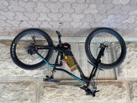
I have made the modification on my bike.
I have choose the Neptune 15 BMS.
Then change the resistor shunt of the G510 motor controler by 2x2.5mohms.

By setting 23A in Bafang tunning software, I get around 2000W.
And I can feel it !!!

It's a new bike, love it !
 

Attachments

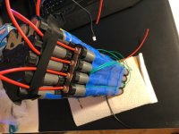
  • 20200319_092545.jpg
    20200319_092545.jpg
    138.7 KB · Views: 3,261
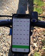
  • Screenshot_20200320-150817_Neptune.jpg
    Screenshot_20200320-150817_Neptune.jpg
    71 KB · Views: 3,260
Hey JFK,

Very interested in the Bafang controller mod. Can you supply details? maybe a photo?
 
Early models of the G510 controller didn't have a very good track record surviving the higher current. One known issue was the 5v supply would get spikes and blow some tiny zeners on the board. A TVS diode across the 5v supply or possibly a higher voltage TVS across the battery input might help prevent this failure. Adding additional capacitors across the battery input would also help but there is no room inside. But you could add something in line with the battery wires like you frequently see with RC ESCs.
 
Hi all,

yep, we have time for DIY those days. :thumb:
the original bafang controller is not bad - having 85v/120amps mosfets (derived from printing on mosfets). so it will also take some more watts than 2000 :D … unfortunately it is not a FOC controller…
here the Neptune 20 output (original controller with shunt mod, 80v caps and 19s4p battery and Neptune 20 prototyp BMS - and TVS-diode to reduce controller volts by 18 volts):
Bafang_4s19p.JPG

but to be honest 4135 watts are not easy to handle anymore and of course temperature of motor and controller will rise enormously after heavy load…
normally i use around 3200 watts - which is ok i think (44 amps limit). anyways perhaps i should change the 80v caps to 100v...

nice little grey LG H26 cells, serial connections with nickel plated copper strips combined with nickel strips (sandwich) - should take a lot of amps with low voltage sag/drop :D :
battery19s.jpg
 
garyal1 said:
Hey JFK,

Very interested in the Bafang controller mod. Can you supply details? maybe a photo?

Hi Sorry, long time not on the forum.
Attached is the two shunt resistor.
I have choose to cut half the resistance, I have remove the two 5mohms and replace it by 2.5mohms.
Now in Bafang setting software, when I choose (ex.) 20A output, the controller output 40A.

The controller board is made on a aluminium PCB, it's very easy to add some thermal past at the rear to help heat dissipation, and cost nearly nothing.

For now, I have set it at 23A output without any problem, I use it every days for home to job, around 14kms per days.
Let's see and measure the motor temperature during the warm days of the summer. I probably have to reduce it a bit.
 
barbarossa said:
Hi all,

yep, we have time for DIY those days. :thumb:
the original bafang controller is not bad - having 85v/120amps mosfets (derived from printing on mosfets). so it will also take some more watts than 2000 :D … unfortunately it is not a FOC controller…
here the Neptune 20 output (original controller with shunt mod, 80v caps and 19s4p battery and Neptune 20 prototyp BMS - and TVS-diode to reduce controller volts by 18 volts):
Bafang_4s19p.JPG

but to be honest 4135 watts are not easy to handle anymore and of course temperature of motor and controller will rise enormously after heavy load…
normally i use around 3200 watts - which is ok i think (44 amps limit). anyways perhaps i should change the 80v caps to 100v...

nice little grey LG H26 cells, serial connections with nickel plated copper strips combined with nickel strips (sandwich) - should take a lot of amps with low voltage sag/drop :D :
battery19s.jpg

I have not renforced the battery connector nikel strip, I guess it should be a good idea to reduce the battery resistance once the temp increase.
Any idea about the power lost, keeping the stock nikel strips ?
I'm on a Reention Dorado Max battery pack.
 
-JFK- said:
barbarossa said:
Hi all,

yep, we have time for DIY those days. :thumb:
the original bafang controller is not bad - having 85v/120amps mosfets (derived from printing on mosfets). so it will also take some more watts than 2000 :D … unfortunately it is not a FOC controller…
here the Neptune 20 output (original controller with shunt mod, 80v caps and 19s4p battery and Neptune 20 prototyp BMS - and TVS-diode to reduce controller volts by 18 volts):
Bafang_4s19p.JPG

but to be honest 4135 watts are not easy to handle anymore and of course temperature of motor and controller will rise enormously after heavy load…
normally i use around 3200 watts - which is ok i think (44 amps limit). anyways perhaps i should change the 80v caps to 100v...

nice little grey LG H26 cells, serial connections with nickel plated copper strips combined with nickel strips (sandwich) - should take a lot of amps with low voltage sag/drop :D :
battery19s.jpg

I have not renforced the battery connector nikel strip, I guess it should be a good idea to reduce the battery resistance once the temp increase.
Any idea about the power lost, keeping the stock nikel strips ?
I'm on a Reention Dorado Max battery pack.

I am also on a Reention Dorado Max battery pack ( Frey AM1000 ) :)

i would not recommend to reinforce the nickel strips afterwards with that type of battery case construction. normally you build this reention battery pack type stepwise and cant do it backwards.

voltage sag and voltage drop will become a problem if the combined value is too high - in that case the low voltage regulator might get some serious problems as mentioned by Fechter. i guess this might be the main problem => using a battery that cant deliver the amps based on the cell type/parallel cell count combined with bad serial connections or even nickel plated steel strips => this is the best way to destroy your controller…
i also recommend to use some thermal paste for the controller thermal back plate because originally there is no one used by Bafang.

but with a Neptune 15 you can diagnose it - best BMS ever (my opinion).

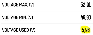
you have a value of around 6 volts. this value is not bad at all. most of the voltage difference is normally caused by discharge drop of cells. so it is always important to choose the right cells and right amount of parallel cells.
dropsag.JPG

another value is also interesting:
temp.JPG

this means your pack temp is lower than your fet temp. this can be a hint that your negative and positive pole connections/strips (through which all your current is flowing) are getting hot -> copper wires are transferring heat to your BMS and finally to your mosfets.

my original 48volts battery with weak serial connections and weak positive and negative pole connections had up to 46 degrees fet temperature. having 3times the watts my own built battery has only 30 degrees or max fet temp is equal to max battery pack temp (have a look at my photo).

finally i would say your battery can deliver the amps you selected - not perfectly but it will work.
 
Is there a sine wave controller that works well with the Ultra and allows functioning torque sensor? 52v or 72v
I haven’t made up my mind as to which voltage I want to use yet.
 
barbarossa said:
Hi all,

yep, we have time for DIY those days. :thumb:
the original bafang controller is not bad - having 85v/120amps mosfets (derived from printing on mosfets). so it will also take some more watts than 2000 :D … unfortunately it is not a FOC controller…
here the Neptune 20 output (original controller with shunt mod, 80v caps and 19s4p battery and Neptune 20 prototyp BMS - and TVS-diode to reduce controller volts by 18 volts):
Bafang_4s19p.JPG

but to be honest 4135 watts are not easy to handle anymore and of course temperature of motor and controller will rise enormously after heavy load…
normally i use around 3200 watts - which is ok i think (44 amps limit). anyways perhaps i should change the 80v caps to 100v...

nice little grey LG H26 cells, serial connections with nickel plated copper strips combined with nickel strips (sandwich) - should take a lot of amps with low voltage sag/drop :D :
battery19s.jpg
Hoping you can point me in the direction of where you placed the TVS Diode. I can handle the replacing of the shunt resistors and caps. I plan to run a 20S battery (will replace caps with 100v.)
Thanks!
Jeremy
 
Hi,

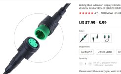
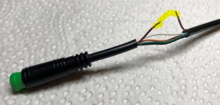
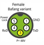
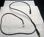
TVS diode is placed between voltage supply for controller and controller - using the display controller connection ( controller voltage feed - 5pin HIGO = green plug). I used a Bafang display cable extension from aliexpress and soldered the TVS diode in.

aliexpress.JPG

TVS diode is placed between brown cable (P+ power supply).
Wire.JPG

display_plug_brown.JPG

if you have 78 volts and put a 16 volts TVS diode between = 62 volts for the controller.

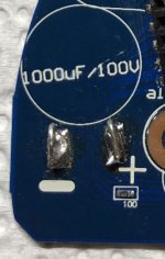
meanwhile I also use 100 volts caps (1000uF and 560uF) - a little more than specified by Bafang :lol: it is really funny: Bafang printed "100V..." on the controller board and in fact they use 63 volts caps.

Bafang1.JPG

Bafang2.JPG

but hey, caps are not really the problem.
85 volts mosfets means that you normally only should use 80% = around 70 volts. 78 volts is already borderline. even better would be 18s and charge up to 4.1 volts each cell group = 73.8 volts.

and I totally forgot: Anderson battery connectors should be replaced e.g. by XT60 (in case of using higher current).

cheers
 
Thank you!!!
I will test my luck with running a 19S battery but may run 52v to start at 46 amps.
1) Can you clarify which specifications of the TVS Diode? does it need to be different based on what voltage battery you're running?
https://www.digikey.ca/en/products/filter/tvs-diodes/144?s=N4IgjCBcoLQExVAYygFwE4FcCmAaEA9lANogCsIAuvgA6pQggC%2BLQA
2) clarify what wattage and package size are the 2.5ohm resistors
EDIT:
?CLAMPING VOLTAGE: would be the max voltage i'd see from my battery. so If I'm running a 80v battery, I'd want to have it back down to ~63max voltages. so Clamping should be around 17V+?
?REVERSE STANDOFF VOLTAGE: your operating voltage of 5v?
?REVERSE BREAKDOWN VOLTAGE: the point where it will start working again?

last, does these modifications need to be done if you're pumping more amps only and keeping voltage?

Thank you again! As much as I like the Phaserunner, I want a 'factory setup' for my new bike.
barbarossa said:
Hi,

TVS diode is placed between voltage supply for controller and controller - using the display controller connection ( controller voltage feed - 5pin HIGO = green plug). I used a Bafang display cable extension from aliexpress and soldered the TVS diode in.

aliexpress.JPG

TVS diode is placed between brown cable (P+ power supply).
Wire.JPG

display_plug_brown.JPG

if you have 78 volts and put a 16 volts TVS diode between = 62 volts for the controller.

meanwhile I also use 100 volts caps (1000uF and 560uF) - a little more than specified by Bafang :lol: it is really funny: Bafang printed "100V..." on the controller board and in fact they use 63 volts caps.

Bafang1.JPG

Bafang2.JPG

but hey, caps are not really the problem.
85 volts mosfets means that you normally only should use 80% = around 70 volts. 78 volts is already borderline. even better would be 18s and charge up to 4.1 volts each cell group = 73.8 volts.

and I totally forgot: Anderson battery connectors should be replaced e.g. by XT60 (in case of using higher current).

cheers
 
tatawaki said:
Thank you!!!
I will test my luck with running a 19S battery but may run 52v to start at 46 amps.
1) Can you clarify which specifications of the TVS Diode? does it need to be different based on what voltage battery you're running?
https://www.digikey.ca/en/products/filter/tvs-diodes/144?s=N4IgjCBcoLQExVAYygFwE4FcCmAaEA9lANogCsIAuvgA6pQggC%2BLQA
2) clarify what wattage and package size are the 2.5ohm resistors
EDIT:
?CLAMPING VOLTAGE: would be the max voltage i'd see from my battery. so If I'm running a 80v battery, I'd want to have it back down to ~63max voltages. so Clamping should be around 17V+?
?REVERSE STANDOFF VOLTAGE: your operating voltage of 5v?
?REVERSE BREAKDOWN VOLTAGE: the point where it will start working again?

last, does these modifications need to be done if you're pumping more amps only and keeping voltage?

Thank you again! As much as I like the Phaserunner, I want a 'factory setup' for my new bike.

yep, my intention also was to use the phaserunner (I have the v1.3 Bafang controller in my Frey AM1000 with normal hall sensors so no problem, my other bike has the v1.5 controller with integrated chip hall sensor) but before I just wanted to check the maximum capabilities of my original controller or let's say : try to kill the original controller - but hey, it works stable as a rock since 1000km. but if you have the v1.5 with integrated hall sensors as a chip and no unused normal hall sensors = forget it !!! your phaserunner experience won't be nice... you can only run it sensorless. Having the v1.5 I recommend having a spare part controller - no chance to use something else without normal hall sensors. I buy the spare part from the guys that produce the Excess/Innotrace controller so after their modification they have original controllers (v1.5) left and sell them.

yep, 46 amps seems to be the sweet spot ( 23 amps in controller software).

TVS diode is much more simpler and these are cent articles ( 50 pieces = 4-5 Euro). In fact I use an 18 volts reduction in my setup ( don't forget: this is transferred in heat but not much). I don't have the digikey numbers but taken a photo (P6KExxCA where xx=voltage drop):
TVS.JPG

these diodes are always reducing e.g. 18 volts , it doesn't matter what battery you use. but of course for a 52v battery voltage will be too low using 18 volts reduction (undervoltage protection will kick in). for that reason I soldered a JST plug to the display extension cable to put in different diodes/to change the diode or to short it for "original use".
JST.JPG

the modification is not necessary if you only want to pump more amps. you can use up to 15s batteries with the original setup ( 62.9 volts max).

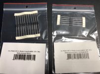
I don't use 2.5 mOhm resistors. controller layout is not very thick and hard to solder caused by the heat spreader. to avoid damage of the controller I simply soldered 2x 5 mOhm resistors over the exsting 2x 5 mOhm resistors (you can take every 2512 smd resistor but I recommend a mimimum 2 watts specification). resulting in 4x 5 mOhm resistors. not perfect but works without any problems (heat is not transferred directly to the board).
If you have an eggrider v2 display you can adjust the ampere multiplier. so if you choose "2x" (having 4x 5 mOhm resistors or 2x 2.5 mOhm) you will see the correct amperes,volts and watts (until you don't use a TVS diode). really nice.

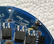
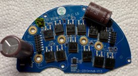
one last advice: changing the originally caps you should "save" the legs of the original 63volts caps. then solder the legs to the legs of your new 80v or 100v caps. so you won't need very much heat and you don't have to solder directly to the board. don't forget to "glue" them again with high temp silikon (to protect the underlying smd parts and of course the caps themselves) and to route the B+ wire in a different way. I finally protect each solder and the resistors with liquid tape, shunt resistors are marked yellow :
controller.JPG

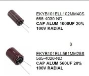
I used these caps:
caps.JPG
 
btw. Phaserunner & Bafang Ultra:
perhaps this thread is a little misleading.
there are v1.3 (and lower version) controllers/motors. these motors all have and use normal hall sensors.
the latest controllers are v1.5 . earlier v1.5 motors still have normal (unused) hall sensors (that was when this thread and the phaserunner modification was made). but they all use the "hall sensor in a chip". but all newer v1.5 don't have normal hall sensors anymore.

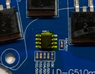
hall sensor in a chip (rotating magnet of motor activates it):
hall.JPG

that means: phaserunner has to run in sensorless mode with new Bafang Ultra motors which is a PITA in my opinion (though phaserunner sensorless mode is one of the better ones on the market).

so the only option that makes sense for new Bafang Ultra motors: Innotrace controller or original controller.

cheers
 
Thanks again, very much appreciated! I think I understand what's happening now.
1) The TVS diode just reduced the battery voltage going to the display to stay within it's operating range
2) Shunt in parallel tricks the controller to pump double the amps.
3) caps allow you to push more volts. The rest of the controller is capable of handling up to '85v' (max on Mosfets).

eggrider looks like a good option! so helpful.

barbarossa said:
tatawaki said:
Thank you!!!
I will test my luck with running a 19S battery but may run 52v to start at 46 amps.
1) Can you clarify which specifications of the TVS Diode? does it need to be different based on what voltage battery you're running?
https://www.digikey.ca/en/products/filter/tvs-diodes/144?s=N4IgjCBcoLQExVAYygFwE4FcCmAaEA9lANogCsIAuvgA6pQggC%2BLQA
2) clarify what wattage and package size are the 2.5ohm resistors
EDIT:
?CLAMPING VOLTAGE: would be the max voltage i'd see from my battery. so If I'm running a 80v battery, I'd want to have it back down to ~63max voltages. so Clamping should be around 17V+?
?REVERSE STANDOFF VOLTAGE: your operating voltage of 5v?
?REVERSE BREAKDOWN VOLTAGE: the point where it will start working again?

last, does these modifications need to be done if you're pumping more amps only and keeping voltage?

Thank you again! As much as I like the Phaserunner, I want a 'factory setup' for my new bike.

yep, my intention also was to use the phaserunner (I have the v1.3 Bafang controller in my Frey AM1000 with normal hall sensors so no problem, my other bike has the v1.5 controller with integrated chip hall sensor) but before I just wanted to check the maximum capabilities of my original controller or let's say : try to kill the original controller - but hey, it works stable as a rock since 1000km. but if you have the v1.5 with integrated hall sensors as a chip and no unused normal hall sensors = forget it !!! your phaserunner experience won't be nice... you can only run it sensorless. Having the v1.5 I recommend having a spare part controller - no chance to use something else without normal hall sensors. I buy the spare part from the guys that produce the Excess/Innotrace controller so after their modification they have original controllers (v1.5) left and sell them.

yep, 46 amps seems to be the sweet spot ( 23 amps in controller software).

TVS diode is much more simpler and these are cent articles ( 50 pieces = 4-5 Euro). In fact I use an 18 volts reduction in my setup ( don't forget: this is transferred in heat but not much). I don't have the digikey numbers but taken a photo (P6KExxCA where xx=voltage drop):
TVS.JPG

these diodes are always reducing e.g. 18 volts , it doesn't matter what battery you use. but of course for a 52v battery voltage will be too low using 18 volts reduction (undervoltage protection will kick in). for that reason I soldered a JST plug to the display extension cable to put in different diodes/to change the diode or to short it for "original use".
JST.JPG

the modification is not necessary if you only want to pump more amps. you can use up to 15s batteries with the original setup ( 62.9 volts max).

I don't use 2.5 mOhm resistors. controller layout is not very thick and hard to solder caused by the heat spreader. to avoid damage of the controller I simply soldered 2x 5 mOhm resistors over the exsting 2x 5 mOhm resistors (you can take every 2512 smd resistor but I recommend a mimimum 2 watts specification). resulting in 4x 5 mOhm resistors. not perfect but works without any problems (heat is not transferred directly to the board).
If you have an eggrider v2 display you can adjust the ampere multiplier. so if you choose "2x" (having 4x 5 mOhm resistors or 2x 2.5 mOhm) you will see the correct amperes,volts and watts (until you don't use a TVS diode). really nice.

one last advice: changing the originally caps you should "save" the legs of the original 63volts caps. then solder the legs to the legs of your new 80v or 100v caps. so you won't need very much heat and you don't have to solder directly to the board. don't forget to "glue" them again with high temp silikon (to protect the underlying smd parts and of course the caps themselves) and to route the B+ wire in a different way. I finally protect each solder and the resistors with liquid tape, shunt resistors are marked yellow :
controller.JPG

I used these caps:
caps.JPG
 
tatawaki said:
Thanks again, very much appreciated! I think I understand what's happening now.
1) The TVS diode just reduced the battery voltage going to the display to stay within it's operating range
2) Shunt in parallel tricks the controller to pump double the amps.
3) caps allow you to push more volts. The rest of the controller is capable of handling up to '85v' (max on Mosfets).

eggrider looks like a good option! so helpful.

Yep! Your conclusions are right. That is exactly the trick !!!

only one little detail is missing - there is an upper and lower controller section - the controller consists of 2 parts. Upper section controls mosfets of lower section, or let‘s say is the logical controller part.

1) The TVS diode just reduced the battery voltage going to the display to stay within it's operating range.

-> this reduced voltage not only goes to the display but also to the upper controller section. low voltage regulator in upper section can handle more than 63volts but anyways it is protected against too high voltage...

or a little easier:

mosfets & caps in lower section = full voltage for motor windings

display & upper controller section = reduced voltage

that‘s the trick :lol:
 
Hi!

Do you know if there’s some kind of overheat protection on stock Ultra? I ran my Ultra outside cover at 75 C. This probably means the inside temps hovered around 150-200 C. I felt a clear loss of power towards the end of my ride. The motor still works.
 
FlyingFinn said:
Hi!

Do you know if there’s some kind of overheat protection on stock Ultra? I ran my Ultra outside cover at 75 C. This probably means the inside temps hovered around 150-200 C. I felt a clear loss of power towards the end of my ride. The motor still works.

Nothing obvious on the board, but it might be some tiny little SMD. More likely you melted the solder on one of the shunt resistors. Did it go back to full power after cooling off?
 
fechter said:
FlyingFinn said:
Hi!

Do you know if there’s some kind of overheat protection on stock Ultra? I ran my Ultra outside cover at 75 C. This probably means the inside temps hovered around 150-200 C. I felt a clear loss of power towards the end of my ride. The motor still works.

Nothing obvious on the board, but it might be some tiny little SMD. More likely you melted the solder on one of the shunt resistors. Did it go back to full power after cooling off?

It has but IMO the motor gets hotter alot faster than previously even if higher ambient temps are considered.

Motor sprockets might require re-greasing.
 
It's possible you have a shorted motor winding. Try rolling the bike backward and see if you have a lot of resistance.
 
fechter said:
It's possible you have a shorted motor winding. Try rolling the bike backward and see if you have a lot of resistance.

I tried. No added resistance. I think it’s just high ambient temps combined with migrated grease out of sprockets. I’m going to re-grease soon when I get the socket to open the engine.
 
FlyingFinn said:
Hi!

Do you know if there’s some kind of overheat protection on stock Ultra? I ran my Ultra outside cover at 75 C. This probably means the inside temps hovered around 150-200 C. I felt a clear loss of power towards the end of my ride. The motor still works.

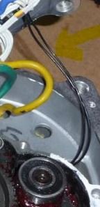
Bafang Ultra motors (at least my two v1.3 and v1.5 motors) have thermistors in motor windings.
thermistor connection = these 2 black wires :
wire_thermistor.JPG
when overheat protection based on too high temperature messured by thermistor kicks in I could see the following behavior (but I only reached the overheating protection level by using the throttle aggressive at high ambient temperatures so far):
1) Throttle does only give a little power in "full throttle position"
2) PAS/Torque system does not deliver full power anymore.
if I remember correctly there were around 10 amps max in "overheating mode" instead of normal around 30 amps - messured with Neptune 15 BMS.
after cooling down full amperage of 30 amps is used again by the controller.
normally overheating protection kicks in very early at not really dangerous temperatures - only my opinion, only tested with "hand on motor-side and controller side" - I still could touch both sides. 75 C - that is really hot and I think I would not have been able to touch it anymore. but anyways that means that your overheat protection worked as designed :thumb: - perhaps it kicked in a little late...
 
Thanks again for all the help thus far. I've decided to stick with a 52v battery for now. I'm currently running 50amps through it. I've put just over 500km and full throttle all the time and seems stable. I want to run more power (maybe slowly work it up to 60amps). Do you think this the stock controller can handle it?
I've added thermal paste on the backside of the controller to help with heat dissipation

worst case: https://www.greenbikekit.com/accessories/bafang-8fun-spare-parts/ultra-g510-mid-motor-parts/bafang-ultra-510-controller-48v-30amp.html

EDIT: I'm at 54 AMPS and the initial test was fine (very cool outside) rode to work in +11c weather and seems ok. Bike feels better, but I think 3500watts is ideal (60amp) for the weight and size of this bike.
IMG_1500 (1).jpg
 
FYI: 52-54Amps is the sweet spot for efficiency. At 56Amps It chews through battery like no tomorrow. motor gets hot hot hot.
 
Back
Top