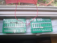
Bestechpower BMS

i saw that they now have the D132 which is identical to the D131 but it has a separate switch to turn the BMS on and off and i had hoped to find a picture of one to figure out how to modify the D131 to operate in that fashion without locking up the output mosfets.
 
their design has very low standby current demands. the D131 uses less than 20uA from the data sheet.

it is really only the BMSs that use optotransistors on each channel for HVC and LVC that consume the most power. each channel has to provide a few (2x3.5)mA to power the optos and maybe another 20mA to run the controller IC.
 
I have bought couple more HCX-167 16S 4.2V BMS'es. I think they have changed it a bit. Now, instead of having extra balancing wire, E.G. 16S - 17 wires, they now have them in 16 wire flavor. B- balance signal is acquired from main B- battery wire and now shows continuity between B- and b- JST connector pin.
I have attached new wiring datasheet.
 

Attachments

  • D167-16S-Li-ion BesTech Power datasheet.pdf
    338.8 KB · Views: 310
henry sent me an email telling me they are introducing new, programmable products:

"Now we are developing some real programable BMS with microchip, now we are under sampling phase.

Hope we can finish end of this month, at that time, I really would like to send you some free samples (free shipping fee as well) for your testing.

This BMS will be able to program any logical parameter and also have Gas Gauge functions and other communications as well.

What’s more, we will not sell those kind of BMS with high price like others are doing, we will keep them as low as we can to open the market and build BesTech’s reputation.

Hope you have some interests to test the samples."

if there is anyone who is competent and would be interested in testing some of their new products then lemme know and will see what can be done. i suspect he will inform me when they are released or they may appear on their website first.

i have always felt that recording the charging profile on a cell basis would be the most useful data to use in creating a history of individual cells to evaluate cell health so i will watch for those in particular. i am not familiar with the programming stuff so it would be useful for someone in the know to help with that.
 
Awesome. I hope he gets them out on the market. All of that is certainly possible with modern hardware. It would be beautiful to be able to program the desired cutoff voltages, etc. and have a way to monitor things remotely with a data connection.
 
I have bought a 131 for about 2 years ago. A mounth a go I bought 2 new ones but the old one had 9-8-8 connections, The new BMS has 8-8-8 connections.
How to connect this to lipo 6s this has 7 balance wires.

Help me please.
 
Its a bit confusing on the new bms. B1(First pin on bms jst) goes to batteries 1st and 2nd cell series junction (negative side of the pack)
Programmable bms is good news, could of been sooner thou. We have new bms here in europe, programmable, with BT, temperature sensor input, fan or heating element controll, external charger switching controll. Linky:
http://www.e-motion.lt/2015/05/22/labiausiai-over-engineered-diy-baterija/
 
Yes it is. I have 4 lipo 6s of 12 amps in series. Each lipo has 7 balance wires coming out of the housing. The positieve and negative thick wires are connecting in series.
I like the BMS on my old battery pack thats why I ordered a new BMS so I could build a second battery pack to have a longer range.
But this new BMS has only 3 times 8 connections on it. The old type had 9-8-8 connections for the balance wires.
Has some one a drawing how to connect the new BMS. It would make my life a lot easier.
 
dnmun said:
henry sent me an email telling me they are introducing new, programmable products:

"Now we are developing some real programable BMS with microchip, now we are under sampling phase.

Hope we can finish end of this month, at that time, I really would like to send you some free samples (free shipping fee as well) for your testing.

This BMS will be able to program any logical parameter and also have Gas Gauge functions and other communications as well.

Has this happened? Progress?
Hoping!
 
I will get some samples next week i hope. it's the D270. But it's far from being perfect, so it's more like beta testing ATM

I propose you stick to a different product if you want to get something reliable for a real battery, not just for testing/development
 
dnmun said:
henry sent me an email telling me they are introducing new, programmable products:

"Now we are developing some real programable BMS with microchip, now we are under sampling phase.

Hope we can finish end of this month, at that time, I really would like to send you some free samples (free shipping fee as well) for your testing.

This BMS will be able to program any logical parameter and also have Gas Gauge functions and other communications as well.

What’s more, we will not sell those kind of BMS with high price like others are doing, we will keep them as low as we can to open the market and build BesTech’s reputation.

Hope you have some interests to test the samples."

if there is anyone who is competent and would be interested in testing some of their new products then lemme know and will see what can be done. i suspect he will inform me when they are released or they may appear on their website first.

i have always felt that recording the charging profile on a cell basis would be the most useful data to use in creating a history of individual cells to evaluate cell health so i will watch for those in particular. i am not familiar with the programming stuff so it would be useful for someone in the know to help with that.
Anything Dnmun?
 
nope, i was telling crossbreak i am not familiar with the 270. i thought it was the big 40 mosfet model so i need to look for it. i do not get free stuff to sample but if he can i think that would be useful too. i was just glad to get enuff ordered together to get good prices and that was enuff. of course now i have dozens of extra BMSs laying around too. wasted more money on this stuff than women. of course no way that can be true but does seem like it.
 
dnmun said:
nope, i was telling crossbreak i am not familiar with the 270. i thought it was the big 40 mosfet model so i need to look for it. i do not get free stuff to sample but if he can i think that would be useful too. i was just glad to get enuff ordered together to get good prices and that was enuff. of course now i have dozens of extra BMSs laying around too. wasted more money on this stuff than women. of course no way that can be true but does seem like it.
Hah! Better than bottles of whiskey... You could always part with a few? If you have one suitable for 48V 18650 build, I'd help you get your focus back on women.
 
Is it possible to wire 2 identical bms's in parallel to run double the discharge current ?

So 2x 100a bms now can take 200a discharge ?
 
yes i wired two D131 BMSs together on my 24S 87Ah lifepo4 pack. but i used a master/slave arrangement. i also rewired the slave power board of one BMS from 15mosfets to 20 mosfets on the slave power board. so that gives me a total of 35 IRFB4115 in parallel so it will handle up to 350A but i have to add some solder to the shunt for that.
 

Attachments

  • DSC01914.JPG
    DSC01914.JPG
    55.9 KB · Views: 3,056
  • DSC01915.JPG
    DSC01915.JPG
    63.9 KB · Views: 3,056
  • DSC01918.JPG
    DSC01918.JPG
    73.7 KB · Views: 3,056
  • DSC01919.JPG
    DSC01919.JPG
    75.6 KB · Views: 3,056
Ok thank you for the answer. A 14s 250a bms is costing 415 Usd. So maybe I can put 2x 100a bms in parallel
 
yes. these BMS have an over current cutout of about 80A as i recall. 43% of the current flows through the BMS with the over current detection. so this stock set up will handle 187A continuous before cut out. you can easily force that up over 250-300A by adding some solder to the shunt wires to increase the over current cutout. the solder is only needed on the master shunt if you follow this procedure i outlined of converting the slave from 15 to 20 mosfets in parallel.

total cost is about $130 for 24S for both of the BMS.
 
dnmum

I am just about to place an order for two or three d131's, but wanted to double check first.

My bike is generally pulling a max of 80-90..usually 20-30 in the cruise..but the CA does show maximum (even with block time of zero) of up to 140 amps.

Is the D131 going to handle this in stock configuration, or am I going to get a power cut under acceleration.

if modification...can you elaborate on how this is done ? Just a straight shunt mod?

Cheers

Neil
 
you can use two in parallel with each other if you want to also. if you use one and wanna solder up the shunt then first be certain you have an idea of what your max current is and if it causes the BMS to cut off then solder the shunt a little bit and see if that allows it to work. don't use so much solder that you lose the response time to a short on the output.

i use a pair of D131 as master/slave on my 87Ah lifepo4 pack. i could have soldered the shunt but decided to make the master/slave instead. that gives me 200A+ of output current and 350mA of balancing current.
 
Hi thanks
Not the space for a pair ..otherwise I'd just use their bigger D-171 that does 250 amps

The d-131 is the ideal size, just needs a few more amps just for the peaks on acceleration/ startup.

Rather than soldering up the shunt. what about adding extra shunt wire. At least then yu can add a controlled amount. what is the current shut value ? did you ever know that ?
 
Great thread here - happy to have found it. Thanks to all those who have contributed up to this point - good read.

I want to integrate a PCM from bestech into my 20s25Ah RC LiPo battery but I'm not going to sugarcoat it, this is a sect of battery building that I've avoided for along time because it's outside of my immediate understanding. But I know it's something I need to do and I'm confident I could wire it up. I sent bestech sales an email asking for pricing and availability for the HCX-D131 and the HCX-D170 because they seemed to fit the profile of the bike I'm building. For reference, it's a heavy vector bike using a programmed 18fet with beefed up traces. I'm hoping to push 50mph with it - but, as it's not assembled yet, I have no idea what the end settings will be.

Sales from bestech asked me for a couple of tidbits of battery/use information that, for others reading this post and are thinking of contacting them

continuous charge current - no charger yet, so no idea. Can I use a meanwell bulk charger as my charger with BMS?
continuous discharge current - this would be whatever MaxA is via CA?
peak current and the lasting time for the peak current - here's where I'm stuck.

Peak discharge is still going to be whatever CA shows me as MaxA? And the lasting time for peak current... this is going to be the "overcurrent detection delay" in XPD, right?

Any recommendations for me as far as a model? I have read plenty of success with the D131 here, if I were to choose that model I would likely opt for a shunt mod (if needed) to increase output rather than using them in parallel.
 
Just quick reply

the D-131 according to Henry, last e-mail from him. is good for bursts. 20 mili seconds or so of 140 amps

you will need to order two of them, they generally seem to have a minimum order quantity of x 2 units.

my pack is similar to yours 20 series 20 Ah Nanotech lip with beefed up 18 FET controller.

I see peaks ( with block tine at zero) or 130 amp on the CA , averaging acceleration of 80-90 this is with a 5304 motor in 26 inch wheel

I charge at 20 amps with a BMS battery 2kW charger. Yes you can use a meanwell. Set it to a higher voltage than yo would for normal bulk charging, I believe, so it allows the BMS to do its job and bring all cells up.

Even with block time ( overcurrent detection delay) set to zero, you still do get momentary peaks. I'd definetly set it to zero. as soon as you go above that with a power ful pack abnd current hungry motor you can start pulling big currents and poppin fets..daisy chain then other go too.

sorry for bad typing ...in a hurry..about to go flying
 
Back
Top