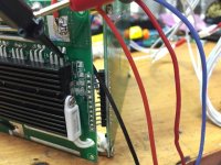
Bestechpower BMS

NeilP, thanks for your reply here, answered all the concerns I had.

Some updates here, looks like the MOQ for the D170 is actually 1 which lends itself as a decent option. The salesperson (not Henry, but Ada) has been very easy to work with. I have some minor tweaks that I think would be good via the criteria that they sent over via the datasheet. Let me know what you think. Side question: these things have IC right? Are they just programming these parameters in or are they truly based on the components installed only? If the former, what's the point of programming the amps down?

DATASHEET
QAynZtq.png


Maximal continuous discharging current: 100A - - - (just for the additional overhead)
Over charge detection voltage: 4.24v - - - (base 4.28 seems pretty high...)
Over discharge detection voltage 3.30v - - - (when my LiPo balance charger does charge/discharge cycles, it usually only goes to 3.30...)
Over discharge release voltage 3.30v - - - (Should release be slightly higher here to accommodate for voltage sag under load? )

For those who've ordered these before, do they come with the sense wire JST plugs or should I request that? I'd very much rather spice wire connections to a premade plug than attempt to make a quality one.

Thanks again for the help, excited to get this thing ordered.
 
All of the adjustable settings..I was not sure either.

Balance I thingk I asked to be set at 4.18.

you see there is an over voltage protection AND a balance voltage.

I think I asked for 4.22 over volt and 4.18 balance.

with down to 2.6 as the low voltage..

but I did ask this question before ,as to what settings should be asked for, but did not get a response for here. maybe you will get more luck and we can get an answer.
 
I don’t order from this outfit anymore but when I did I found my orders processed much faster if/when I stuck with “standard” Li-ion OCDV 4.25V, ODDV 2.8V, BVSC 4.2V, settings for D167, D141, D245 BMS.

Going with unusual/custom values always seemed to add a week or more to squeeze things into the production line.

Whenever I used the values provided on the spec sheet, I always got the DHL ship notice within a couple days of placing my orders.
 
and did the standard values seem to work OK?

Not had any real dealings with BMS until before. Well fitted a couple form ...BMS battery I think , then not monitored there performance.


How do the these perform ? any feedback ? or did you like me, just plug em in and let them get on with their job?
 
Standard values work just fine. Remember, they build a shit-load of these things so I’ll leave that part of the “design” to the experts.

The only real gripe(s) I have about these BMS/PCM is the balancing current is so minimal (about 80mA) it takes a very long time to correct any significant out-of-balance condition when used on 5-10-15-20Ah cell groups.

However, the more serious issue is that I’ve suffered many shorted balance transistors on D167, D141 BMS. Obviously, this conducts balance current across the resistor for a particular channel and if you’re not paying attention it can and will drain cells to damaging levels.

The pros say it’s my fault for using connectors for my setups and that may be true. But, if they’re so god damn fragile and since they do very little real balancing (unless you wait for days) I’d rather not have the balance circuit at all.

My fix is that when I suffer shorted balance channel transistors I merely remove the SMD resistors which prevents any current drain on that channel.

Majority of the time I never experience out-of-balance issues but if/when do get a little whack (usually due to a shorted balance channel transistor) I just charge single cell through the balance leads.

Another thing that’s really handy for working with these BMS/PCM is to fabricate parallel JST dongle so you can plug in a CellLog or similar to actually see WTF is going on. Otherwise it can be fairly mysterious…

But as far as OVDV and ODDV protection is concerned they work great. Saved my ass and cells on some occasions and for that reason I run them on all my packs.
 
Ykick said:
I don’t order from this outfit anymore but when I did I found my orders processed much faster if/when I stuck with “standard” Li-ion OCDV 4.25V, ODDV 2.8V, BVSC 4.2V, settings for D167, D141, D245 BMS.


Did you find something better?

On the OVP level, it seems most of them are set pretty high which I think is intended for charging at high rates.
When charging at 1C or so, the cells have a "reverse sag" which elevates the voltages. If you are charging fast and hit 4.28v, the cell voltage will immediately drop when the charge current stops.
 
fechter said:
Ykick said:
I don’t order from this outfit anymore but when I did I found my orders processed much faster if/when I stuck with “standard” Li-ion OCDV 4.25V, ODDV 2.8V, BVSC 4.2V, settings for D167, D141, D245 BMS.


Did you find something better?

On the OVP level, it seems most of them are set pretty high which I think is intended for charging at high rates.
When charging at 1C or so, the cells have a "reverse sag" which elevates the voltages. If you are charging fast and hit 4.28v, the cell voltage will immediately drop when the charge current stops.

Not really better just cheaper and less BS (no MOQ) to grab something suitable off eBay. Pretty much same as BMSBattery offerings but at least if it doesn't arrive or totally fubar eBay/PayPal will help make it right.

My needs are lame compared to many here as I'm mostly dealing with 15-30A systems. The eBay caveat which matters for me is if I need 30A, buy 60A rated BMS If I only need 15A, buy 30A BMS. $30-$40 w/shipping I'm happy.

You're probably right about OVP - I charge mine 1-2C and everything seems to settle down to around 4.18V. At least on fresh stiff cells.
 
D170 is paid for. I payed right via paypal. Ada assured me that tomorrow the request to produce it would hit the floor. Once manufactured, the board would arrive within 4 working days after the carrier had marked it being in transit.

Note on this unit: it's pretty big (220mm L / 120mm W / 50mm tall) / it's 20mm longer than an infineon 18fet/ 120mm wide (that's 30-40mm wider than the 18 fet) and about as tall. For Vector owners, it will fit pretty well on the frame (vector frame is is 125mm wide) in top most part of the frame where there is a 250mm length total before tapering off to the front of the bike. The cost of unit increased based on maximum discharge/charge - I went with 100a max continuous (150a for 1sec bursts) and 25a charging continuous. Pictures inbound when it arrives. I'm hoping to document the install here in great detail.

I do have some follow up questions: here is the wiring diagram provided to me:
VzH4VzX.png


i39IHgZh.png


Above sort of illustrates some gaps I need to fill. First and foremost are the balance leads: these are 5s paralleled packs via the mains and balance leads. The mains are put into series while the balance leads (at current) are simply in parallel. The balance leads for my 5s packs have 6 wires, 1st wire being black cell 1- negative where each there after is cell 1+ / cell 2+ / etc.

My question... so when wiring the BMS, I only want to be connecting the cell + wires, right? Remove black cell 1- wire completely and then connect up the cell + wires to the BMS. Can someone confirm/steer me in the right direction here? Am I even close?

The order in which the sense wires are connect DOES matter here, right? e.g Cell1 should be 3.7v, cell2 should be 7.4v all the way up until cell20 at 74v. I can check this via a multimeter once the mains have been put in parallel. Now, when I get to cell6, am I going to want to be testing it with the negative from cell1 or from the negative on cell5 (black balance lead from 2nd paralleled balance lead)?

Lastly, no indication of where P - is: I'm sure when inspecting the actual unit I'll be able to locate it, but for now, it remains a mystery as to it's position on the board.

Thank you for your guidance here. These questions were difficult to express, if they lack clarity please be patient with me!
 
On the 24s d131 boards I just got from bestek they didn't have the low cell negative connected either. There's an empty pad for it, but they didn't use a 9 wire connector for it, just an 8 wire like the other 2, so it only brings out connections for the + sides of each cell. I may solder in a single wire for the low side negative or I may not. Depends on how I feel when I hook it up. It's not needed, as the pad for it is common to the B- connection for the battery pack. In the photos of the board in the first post, you'll notice they did use a 9 wire connector on the ones he got. Guess they decided to keep it uniform with three 8 wire connectors now.
The D131 boards I got has 3 big pads labeled B-, C-, and P-. The remarks on the data sheets was confusing to me compared the the drawing, as is yours. It appears that my P- is the same as your Dis-, and your P- is the same as my C- .
The battery packs main positive lead does not connect to the board at all. That was what was confusing to me, and it appears may be to you too. The board gets its power from the sense leads and only controls the negative side of the battery pack. So for your board the connections are like this.
Battery pack main positive does not go to the board at all but connects the controller (load) positive. It's also where you would connect the positive side of the charger.
Battery pack negative connects to B-.
Controller negative connects to Dis-.
Charger negative connects to P-
I'm pretty sure that's right for the way your board is labeled in the drawing you have.
 
On the balance wires, remember that if your board doesn't have a negative connection for the first cell, don't use the first balance wire from your pack to the sense wires from the board, or you'll have it all screwed up.
 
I hang the connector in and let the wires hang like a parachute. Plus love an extra set of sense wires for I need to know. What are the amp limits ?
 
dnmun: do you know a good way to use a low current switch to turn the hcx d131 on/off? we once discussed that by using the thermistor signal you can make the bms turn off. but you need to cut main power and apply it again to make the bms work. not very handy.
what if i would cut the gate signal of the output FETs, and close them with the switch? good idea or not?
 
So I think I figured the wiring for it completely, studying http://imgur.com/jGKMG.jpg and http://www.servovision.com/LifePo4%20Pouch%20Cell/BMS%2048V%204A,45A.jpg really helped me. I didnt know the short line represented - and the long line in the diagram represented +. Here are my final assumptions submitted for confirmation.

Indeed what I'll need to do is parallel my balance leads. I will take a 5s balance lead extension plug, decap the non-battery connection end, remove the cell 1 negative wire, and then splice the connections to the BMS balance plug and then connect to the correlating battery balance leads. As wes said, it is definitely the case that cell 1 negative does not get plugged in.

The more I thnk about it, the cell ORDER must certainly matter.

What I will need to do is grab the multimeter, stick the negative probe in the load lead negative connector, and stick the positive probe to the individual balance wire JST to verify the voltage thusly identifying the cell# in series, is this correct? Even though 25Ah pack #2 isnt serialed via the balance leads, because they are via the load leads, 25Ah #2 will show me a voltage of 22.2v for the first cell positive (2nd balance lead wire) when doing this test, is this also correct?

As far as the load leads are concerned, the battery load lead positive will need to a Y, where it can be connected to a charge plug and also to the ESC plug. The battery load negative will have an in pad for connetion. The BMS will have a negative pad out for the charger and also a negative pad out for the load.

When looking at the diagram at first, it was not intuitive for me bcause I have only used LiPo and never made a 18650 battery (its hot on my bucket list though), but when I think of these connections in terms of what voltage it should have it becomes far more clear for me. For instance, with the diagram I posted for the D170, look at cell 20... The illustration made me think... "So I need to have cell 20 paralleled with my positive load lead?" The answer is no, cell 20's balance lead will be 74v just like the load lead.
 
markw said:
I didnt know the short line represented - and the long line in the diagram represented +.


Yikes. I am not being negative , but that info is really very basic pre school 'tinkering with a flashlight ' bulb and battery kit type knowledge.

Bearing that in mind, please be very sure before you make any connections. One wrong connection will very very likely kill a BMS dead. I have a pile of 4-5 here from well meaning tinkering 'customers' who have tried to go it alone after seeing me do them.

I have not read up back on your previous posts, and I am on iPhone here now, and don't have time to go back and read up, so I shall refrain from commenting on your questions.
Just wanted to shout out a word of warning to you, as you are obviously prepared to ask questions and take advice, and even admit your lack of basic knowledge. I have seen too many people come to me locally for help, claiming they know electrics, just want help in what to order, then you start speaking and drawing basic diagrams like you link to, and their eyes glaze over.

Good luck,
 
Yeah that symbol one short - and one long - means One cell.
Where as you have a 3 layer one of those in a pyramid or triangle, then its ground.
 
i just looked for a way to turn the bms on and off and getting rid of the inrush limiter to reduce complexity and error sources.
so i followed gate signal line and the output gates are all connected and then transfered through the pin headers #5 and #6 to the other board where they end in a little transistor. so i cut the pin headers and checked that gate voltage was zero.

no connection between B- and P- anymore with cut pin headers. when you connect them again with a regular switch the gate voltage climbs from zero to 8v+ in one to two seconds. after disconnection it takes some seconds to fall again. this may be shorted to almost no time when connecting gate directly to B-.

here is the pic and a short video:

IMG_0167.JPG
and here's the video

[youtube]uQcyKi_ZoKs[/youtube]

let me know your thoughts. good idea or not? would it be safe to switch gate to B- to acchieve an instant off?
 
If the gate is only pulled up by a resistor, then it should be OK to just short it to the source to turn off the FETs. On some designs the gate is pulled up by a chip or transistor that might not be happy with the short. It may be possible to trace out the gate drive circuit to see how they are doing it.
 
But the gate is removed from the transistor switching it. That trace is cut and replaced by the switch. And the switch toggles the gate between the transistor and gnd. So the transistor's output will never be connected to gnd which obviously could kill it. Should i draw a sketch?
 
Ah, yes that should work no matter what. SPDT switch.

If there is any load on the output, even a tiny bit, it might not turn back on. One way around this is to place a big (470 ohm?) resistor from the B- to P- connections to make sure the voltage comes up enough to allow the FET to turn back on.
I know this is true if you use the temp sensor to turn it off. If you switch the gate line, it might not be a problem.
 
Could you please explain why this could happen - i just cut the gate supply. Isn't this how FET-switching normally works? Would cutting the supply voltage to the little transitor that drives the gate voltage be the better solution?And wouldn't the resistor allow permanent current flow - something i want to avoid?!
 
If you use the temp sensor as others have tried, it essentially 'trips' the safety circuit and drops the gate drive. The circuit stays in the tripped mode until it sees the load clear. If the controller is connected, the drain will be enough to keep it from resetting.

If you can cut the trace going to the gates and install a switch that grounds the gates, it should do what you want.
The only problem might be when you turn it back on, it there will be a big current spike as it charges the controller caps.
It may actually be possible to integrate the precharging circuit into the BMS.
 
D245 BMS comes with an e-switch and it basically accomplishes no spark battery connection. With BMS turned off, connect to controller, switch it on and power's delivered with no spark.

The e-switch wires attach near the temp sensor wires so it's likely using some point around the temp switch? Turning off is easy but getting them back on seems to be the hurdle.

Unfortunately, i no longer have any D245’s in my possession or I'd try to grab some pics of the e-switch area.
 
i already have the d131 installed and it's perfect for my needs. high discharge current and high balance current.
@fechter: if i compare the raise time of the gate voltage to your inrush limiter they are very similar. there is a nice ramp up which should charge the caps slowly w/o a lot of current. i guess i will just test it and we'll see. :)
 
i tested the BMS with the disconnected GATE line. what worked fine on the bench didn't work with a controller connected.
there is some way that some current find it's way through the BMS w/o gate connected.
and once there is a load, switching on the GATE doesn't work. as fechter did say.
i will try with the resistor.
 
Back
Top