BMC gear-drive motor won't restart

Joined
Apr 15, 2008
Messages
63
Location
Blackburn Hamlet, Ottawa, Ontario, Cannada
I have a BMC hub motor in the front wheel of a cruiser bike. The wheel will start and run as long as there is power applied by the throttle. However, after coasting, the motor will not respond again until it comes to a complete stop and rests for a few minutes. To isolate the issue, I changed the battery and used an old pack with no BMS. The same symptoms exist so I eliminated the BMS shutting the pack off. The problem exists with or without the CycleAnalyst connected, I have set the CycleAnalyst speed to 99 to eliminate that cut out possibility. I also raised the Amps cut off to 30 Amps so the CycleAnalyst can't be the problem. I also swapped out the throttle with a brand new throttle and the same problem exists. Lastly I swapped out the Crystalyte 20A controller with an Infineon 25A controller and same problem. The motor runs until I let it coast with no power, then it won't re-start. Since I have been able to re-create the problem with 2 different batteries, two different controllers and two different throttles, I have to conclude the motor is the source of my pain. What could it be? Weak hall sensor signal? Incompatible controllers? Ghost in the machine?
Any help is appreciated.
 
I had a very similar issue with a BMC. Went down the same roads to remedy - also to no avail. Couldn't find a hall/phase connection or shorting issue, etc, etc.

I finally identified it as a hall connection issue with the hall test part of an ebike tester and by wiggling/pushing/pulling/flexing the motor cable where it enters the shaft. I bought new hall wiring in preparation to pull new wiring, but then when I opened then motor to begin surgery ----

  • ...it turned out to be a bad solder joint on a hall wire to a pad on the PCB. It was making enough contact to operate normally until the motor heated up, everything expanded a bit, and the connection pulled - putting the hall to sleep. A few minutes later, the stator would cool a bit and it would mysteriously wake up. It turned out that the connection was being held in place by a drop of epoxy from the original hall PCB installation. Cleaned the end, resoldered, fixed.
After the fix, I subsequently read about another ES member with a bad BMC hall connection. Two cases don't make a trend, but...

Pop the case and try resoldering the hall wires to the PCB. Take a look at (or re-solder) the hall leads as well. You can chip off the epoxy on the PCB without much difficulty to expose the pads on the PCB - don't remove the halls or the PCB - just fiddle with it in-situ. After soldering, a little JB weld from the hardware store will goop it all back together (The steel-filled stuff - high temp but non-conductive). Don't go crazy, just a bit to hold down wiring and cover the solder pads.

I don't know if this is your problem, but it sounds similar and the fix is easy - although removing the wheel and cracking the motor is always annoying...


  • Some info on BMC motor disassembly here. Virtually identical to MAC and there are some posts about servicing them here on ES as well.
 
Thanks teklektik, your explanation of the heat causing the problem is very convincing. This motor is very loud right now. Would an incorrect hall /phase wire combination lead to unnecessary heat and noise? The symptoms occur even on the bench with no load on the motor, just free spinning in the forks.
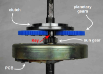
I watched the videos on the disassembly of the BMC motor. I should be able to borrow a gear puller. I see how to get the planetary gears off, but I am not quite sure how to get at the PCB to inspect and re-solder the connection(s). Do I need to pull the gears off to get at the PCB?
 
BlackburnPete said:
Thanks teklektik, your explanation of the heat causing the problem is very convincing. This motor is very loud right now. Would an incorrect hall /phase wire combination lead to unnecessary heat and noise? The symptoms occur even on the bench with no load on the motor, just free spinning in the forks.
I watched the videos on the disassembly of the BMC motor. I should be able to borrow a gear puller. I see how to get the planetary gears off, but I am not quite sure how to get at the PCB to inspect and re-solder the connection(s). Do I need to pull the gears off to get at the PCB?
PCB should be on the other side of the gears.

Dan
 
BMC_gearAssembly.png

BlackburnPete said:
Would an incorrect hall /phase wire combination lead to unnecessary heat and noise?
Yep.
BlackburnPete said:
The symptoms occur even on the bench with no load on the motor, just free spinning in the forks.
Okay - the story is slowly leaking out...
Did this ever work or is this a fresh installation of a new/used motor and controller?

The bench thing doesn't discount the hall issue described above, but it discourages heat as part of the answer.

Be advised that BMC motors are difficult to drive and not just any generic controller will work. Symptoms are running very noisy/ratty at low speed and mid-rpm power cutouts under acceleration. AFAIK these only run with BMC controllers, old analog Crystalyte controllers, or XieChang (Infineon) controllers from EM3EV or Lyen. If this motor worked before then this is not an issue, but if you are just getting going, the controller is suspect...
 
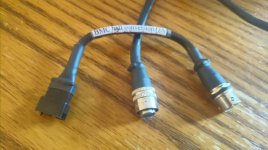
bmc_connector1.jpgYes, I picked up the parts used, but the old Crystayte controller is supposed to be the one that works for this BMC motor. It was part of a working bike project, but I never saw the old project in action. The controller is a Crystalyte with a red push button power switch. The controller's hall sensor wire terminates in a five-pin cylindrical plug with a sliding locking collar. There is a short adapter to a five pin flat connector labelled "BMC hall conversion QA", but I have no idea who made or labeled this part. The controller hall sensor wires are the same color pattern matching B-B Y-Y G-G and red-red black-black.
The phase wires are not matching (B-Y G-B Y-G). I have seen another colour sequence suggested that I will try next. Hall B-B G-Y Y-G and same with the phase B-B G-Y Y-G).
Thanks for the PCB location. It looks like I don't need to pull the gears to get at it. Thank to DAND214 for your replies too. Did you have a similar issue with a BMC motor?
 
BlackburnPete said:
Yes, I picked up the parts used, but the old Crystayte controller is supposed to be the one that works for this BMC motor. It was part of a working bike project, but I never saw the old project in action. The controller is a Crystalyte with a red push button power switch. The controller's hall sensor wire terminates in a five-pin cylindrical plug with a sliding locking collar. There is a short adapter to a five pin flat connector labelled "BMC hall conversion QA", but I have no idea who made or labeled this part. The controller hall sensor wires are the same color pattern matching B-B Y-Y G-G and red-red black-black.
The phase wires are not matching (B-Y G-B Y-G). I have seen another colour sequence suggested that I will try next. Hall B-B G-Y Y-G and same with the phase B-B G-Y Y-G).
Thanks for the PCB location. It looks like I don't need to pull the gears to get at it. Thank to DAND214 for your replies too. Did you have a similar issue with a BMC motor?
I have mostly MACs. Have 2 BMC V1 with 9 fet Infinions and they work fine. As teklektik said about the controllers is whar was my problem at first. I do know that color matching was a problem. I do think I went Y-G match hall and phase but that was a few years ago and they are still running. MACs if not a matching controller from Paul, I needed to swap those colors.
When you get it running right, you'll love it.

Dan
 
Find Xlyte to BMC color phase/hall color code here.

There are several permutation of this according to color rotation. That said, since your halls are already connectorized, there's no point in screwing up the tidy shrink, etc and screwing around with them. Since you don't seem to know how the phases were wired originally, there are only a few permutations of those wires - you already know one has to work with the fixed hall combination since it worked before. Just be sure to only apply throttle very gently when trying the phases combos - going WOT can take out the controller FETs on a bad phase hookup. Some folks like to put 5A fuses in the phase leads when doing this to help avoid this issue, but a soft touch will work as well.

Xlyte used those round miniXLR connectors as standard, so shops made up and sold those little miniXLR-to-JST adapters - I've made several myself - nothing special or weird going on there.
 
I already have the wires bare from the motor and controller side. I have been twisting them together and using small blue marrette screw-on connectors to keep them tidy until a final solution. I have the tools and parts to replace the Anderson connectors for the phase wires and I have the inserts for the JST connectors so I may try to re-use the 5-pin JST housings (or I might just solder and heat-shrink it all!). Would the controller still run the motor at all if a FET was blown on the controller? I am going to set up the wiring as you suggested in your link and hope for a working combination. Maybe I won't need to take the motor apart.
Thanks for all the excellent responses on this thread!
 
The halls and phase wires are currently set up as per the link in teklektik's previous post and the combination spins up the motor from a standstill. If I hold the throttle on, the wheel keeps turning under the motor power, but once I back off the throttle, the motor will not restart. Very frustrating. I guess I will be taking the motor apart soon and looking for faulty solder connections like teklektik said in his first reply.
Could the placement of the spoke magnet right against the hub motor body be creating a bad signal from one of the hall sensors? I am going to remove that possibility next, but I can't see how it could affect the outcome while spinning with all those other magnets spinning in the motor...
 
I just checked the voltage on the hall sensor wires, I disconnected the green controller hall wire from the yellow motor hall and put an alligator clip from my digital multi-meter on each wire and carefully rotated the motor backwards until it registered 13.5 volts with the controller turned on. Same with the controller blue to motor green, but there was nothing at all between controller yellow and motor blue. i carefully rotated the wheel backwards in each case but still no Y->B voltage.
Oddly enough, the controller still started the motor with the Y->B wire disconnected. I think this may be pointing to a bad hall connected to the blue wire in the motor.
I thought I would be reading 5 volts in those hall wires. Does 13.5 volts point to another issue?
The more I look at this, the more I am intrigued... (confused??)
Controller/Motor
G->Y 13.5V
B->G 13.5V
Y->B 0V

Phase wires match
Y->Y
G->G
B->B
 
Back
Top