Building the Best Controller

Which side usually blows up in controllers? Low or high? Seems a fair bit of both in the ones I've been sent so far (sometimes just one or the other, sometimes both).

With "regular" controllers, do they shutdown gate drive of both FETs when overcurrent conditions exist, or do they only do the high side? If the former, maybe that's what blows up low side FETs?
 
liveforphysics said:
Lots of talk about the low voltage power, but it's the high-side FET gate drive isolated supply that needs the attention. No boot-strapped crap, a real switcher to maintain a steady +10vdc source above the pack voltage no matter what sort of awful bounceing things happen.

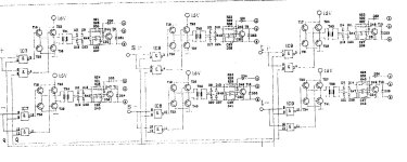
An effective, but I admit somewhat bulky solution to complete isolation of driver and power is the use of a transformer as I used in the controller shown in this thread:
http://endless-sphere.com/forums/viewtopic.php?f=7&t=19993&start=15#p292906
file.php

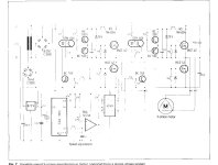
Below is the schematic. Sorry for the poor quality scan. At least there is 6-redundancy in making out the schematic from the observed data. Below that is a simpler opto-isolated high side driver from a Siemens app note, where one could substiture the Zener stabilization with a separate PSU. How about just using the internals of a cheep 12V wall-wart switched PSU?
AAFETdrivers.jpg
SiemensFETdriver.jpg
 
Apologies, I haven’t gotten around to writing a summary in the last 24 hours, however…

Quick Status:
  • I did post the MPS – Main Power Supply detail spec in the Reference section.
  • Modest updates to Block Diagrams (typos and tweaks)

Feedback on MPS – Main Power Supply:
  • Input Voltage can be as low as 15V, and as high as 150V or more (plenty high for all but racers).
  • Main Bus Voltage: Reset to 12V, and settled on regulated by switching, though still accepting input on design, with possible consideration for a transformer.
  • Note: I have defined limits for the Main Bus and AUX circuits. Feedback appreciated when you can please :)
  • We are getting close to critical mass on developing a block diagram for the MPS, and that will likely happen very soon.

Feedback on Driver/FET:
  • Conversation has been focused on how to manage the thermal and over -current sense, shutdown, and recovery mainly in localized hardware. Additionally there is concern over power quality/implementation to prevent blown FETs.
Q: With regard to FET timing, could we consider using an optical interface to the inverter bridge to eliminate delay across the switching? A book I’ve been studying suggests using DSPs found in media players, though admittedly I am swimming into deep water. The section in particular had to do with rotor position feedback on sensorless sinusoidal BLPM drives which I found to be quite illuminating and had me thinking of how to employ a recovery when a motor blows a HE sensor, and provide for our R/C friends in one swoop.

Addressing the Replies:
Fechter » 8/20-13:44 :: I don’t like the MCU engaged either, therefore I have proposed a 4-way switch of OFF|ON|Alarm|AUX wherein Off = 100% off, On = 100% except for Alarm, Alarm = minimum required for Alarming, and Aux = only Aux circuits (freewheel allowed). The Main Connection could have a slow ramp; the concept is documented for the Main Switch though not the Main Connection - noted.

oldswamm » 8/21-13:53 :: Variable Anti-Slip/Posi-Traction: Gold Star for most unique idea of the hour! Yeah, optionally hardwired right next to the throttle: Bring it on! :twisted:

jag » 8/21-16:41 :: Schematics: Tough to read; how about taking a digital image instead of a scan? :)

There’s not enough consensus for me to detail an MCU or Driver spec, so we will wait a bit. In the meantime we'll keep buffing and polishing what we have in the Technical Reference. Please feel free to comment the information.

Thanks, KF
 
I don't want to be the wet blanket, but I think we should be careful about spec creep here. There is a very fine line between a flexible, versatile design and a monstrosity where people are paying for 100 features they don't need to get the 5 they do. It's better to end up with a product that excels at a few things (preferably things that commercial products do not) rather than something that's mediocre at 100 things. Rather than try to integrate every last feature, a better method is to focus on the handful of critical features and let people customize from there. With careful thought, we can make that very easy for them - an extension port here, a well-documented interface there, etc.

I'm a little concerned about this in context of the MPS spec you posted. Your spec calls for 6A from the 12V rail plus for additional supplies from here. If you want Aux1 and Aux2 to be capable of supplying 5W at 1.5V, that's 3.3A. You need to choose a 3A+ regulator - in a linear regulator that will generate a LOT of heat from 12V (~35W) - and the 12V supply needs to be able to supply 3A for each of those Aux supplies as well. 20W @ 3.3V is another 6A (and 52W of heat). Do we support max load on all rails simultaneously? That requires 18A+ from the 12V supply. That's a pretty serious supply, with large components and significant heat dissipation of its own. That means more space, more cost. You could arrange it so that you don't have to populate all those components if you don't need them, but you'll still end up with a significantly larger package than it needs to be.

Sorry if all that sounds negative. But, an important part of the engineering design process is deciding where to draw the line, what features to include and what features to exclude. I'm just trying to start a discussion on what we should exclude. Instead of having a big internal supply with multiple outputs, we could tone it down, but provide a relay control signal to allow external supplies to be controlled from the master switch.
 
rhitee05 said:
I don't want to be the wet blanket, but I think we should be careful about spec creep here. <snip>

Read second post: http://endless-sphere.com/forums/viewtopic.php?f=2&t=20731#p302055
“Imagine now that this is your birthday, you can have whatever you want, and we present the all-inclusive list.”
Read Thread Summation Wed 2010-08-18 http://endless-sphere.com/forums/viewtopic.php?f=2&t=20731&start=15#p302895
“About Noon (PST) Wednesday, August 25 – the Feature Request will close for Version 1.”

These kind and interested parties can add whatever they want under the sun as long as it is germane to the topic. Seriously: I want to listen to all input; the door is open. :)

The specs in the Technical Reference area are drafted as Proposed and Working; nothing is set in concrete - though I am trying to stay on top of consensus early.

After Wednesday then we can form teams and reasonably consider what can be developed within the timeframe. I have no doubt that features will be cut to the down to the knuckle for Version 1.

In the meantime, please contribute – we welcome your good suggestions!

Cheers, KF
 
Speaking of controller FET stages... ;) Looky what arrived :)

fet3.jpg


fet1.jpg
 
:shock: Those things are bigger than the solid state relays in the breaker panel at work that switch 1/3 of the store's overhead fluorescent lighting on and off!
 
liveforphysics said:
Speaking of controller FET stages... ;) Looky what arrived :)
Oh man! I want... I want two for my bike... :twisted:
Hmmm, guess were looking at 00-conductor huh? :D

N _i_ c e!

Let me guess, this is going on your next bike, the one you were riding at Seafair in the pic below?

a_willliams2wsid_675.jpg


:twisted: KF
 
liveforphysics said:
Speaking of controller FET stages... ;) Looky what arrived :)

fet3.jpg


fet1.jpg
So I dont think those will fit inside my methods controler :?
 
Kingfish said:
Let me guess, this is going on your next bike, the one you were riding at Seafair in the pic below?


Nope, this ol' girl is happy adding O2 to HC's for power. :)
Makes a good e-bike rack too. :)

gsxrebike.jpg
 
Arlo1 said:
So I dont think those will fit inside my methods controler :?


Fortunately, the tabs are isolated, all you gotta do is bolt them to a chunk of alumium (maybe use a flat part of the vehicle's frame if it's aluminum), and run a pair of big buss bars down the sides (and pack as much cap as physically possible between the bars), and you've got yourself a FET stage! Just connect a wire to the center tap of each fet. :) Super easy peasy to work with. :)

3parray.jpg
 
amberwolf said:
Which side usually blows up in controllers? Low or high? Seems a fair bit of both in the ones I've been sent so far (sometimes just one or the other, sometimes both).

With "regular" controllers, do they shutdown gate drive of both FETs when overcurrent conditions exist, or do they only do the high side? If the former, maybe that's what blows up low side FETs?

My impression is that it would want to limit or cut off both the high and low side. Good thing to wonder about.
 
fechter said:
Those are monsters :twisted:

I bet they're not cheap though. What's the part number?

They're Ixys VMM 650-01F, currently $50 for two packages from a chap on eBay (although I bought the last ones he had this morning..........).


The datasheet is here: http://ixdev.ixys.com/DataSheet/L401.pdf

They are 100V, 680A, 1.8mOhm devices, with a very low junction to case thermal resistance.

Jeremy
 
Solcar said:
My impression is that it would want to limit or cut off both the high and low side. Good thing to wonder about.
amberwolf said:
With "regular" controllers, do they shutdown gate drive of both FETs when overcurrent conditions exist, or do they only do the high side?

I think you would want to only cut off the high-side, and leave the low side on for at least a short period. Cutting the high-side disconnects the battery, but you want to leave the low-side on so the current has a path to flow through as it decays. If you suddenly cut off the current through the motor inductance the voltage will spike. You could shut down the low-side as well after a short delay.

A fast hardware circuit could take care of cutting off the high-side, then the controller could decide what else is necessary.
 
rhitee05 said:
I don't want to be the wet blanket, but I think we should be careful about spec creep here. There is a very fine line between a flexible, versatile design and a monstrosity where people are paying for 100 features they don't need to get the 5 they do.

I've seen numerous projects here at school. The ones that succeed usually start with modest aims, then over time improve to perfection. The ones that aim for the moon often remain on paper. It of course comes down to the experience of the builder or builder team.
Here on ES we have already had people selling kits and others successfully building them.

Not much more difficult would be to start from a Xiechang, and say duplicate the design Jeremy has posted for low volts, high current 6FET. The builder has to buy the parts, assemble and test. One can imagine other variations of the basic 6FET board for different apps.

Next step would be to add an intermediate driver circuit board to allow higher power FET stages. I'm anxiously waiting for LFP's results on this. Simple versions of these could be PCB layouts for PCB soldered FETs on the diver board. More elaborate would be to specially construct high power buses with short runs, good geometry and minimal inductance etc, so the power routing is optimized and decoupled from the drivers. Hence a high power controller would be a three-layer sandwich: 1/ the Xieachang board, 2/ the driver board, 3/ and finally the power FETs and bus bolted directly to a heat sink.

I'm curious how much of the scaling problem with 2,3,4 parallel FETs that we see on the Infineon controllers sold here can be avoided with better PCB design. The infineon 12 and 18 FET "all FET's in a row" design seems like the worst of the bunch. BMC's 4110 50A controller looks a bit more promising in this respect. Has anyone tried modding that? What MCU? How many electrical rpm does it seem to handle? I need a candidate to mod for my 5-6kW Astro build, but I'm going to push the astro to 10-15k rpm, so I'm looking for 150,000+ electrical rpm.

Designing the MCU part from scratch I suspect will be a whole other can of worms. Newark/Farnell had an article on it in their monthly magazine about a year ago. I've emailed them numerous times for an electronic pdf copy to post to ES, but the sales and interned dudes are stumped by any out of the ordinary request... I'll see if I can look up the reference. I think I posted it before.
 
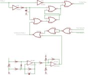
Here's a schematic for a pulse-by-pulse fast current limiter circuit as discussed previously. This is designed to sense current based on the low-side FET Rdson and cut off PWM to all 3 high-side FETs if any phase senses overcurrent.

Pulse-by-Pulse Current Limiter.PNG

IC1B and C form the basic R-S latch, with IC1A added to prevent the R=1, S=1 race condition (S is dominant). IC1D gates the PWM signal based on the output state of the latch ("set" = PWM enabled, "reset" = PWM disabled). IC2A and B buffer the incoming PWM signal and invert it to make the logic work. R1 and C1 set a time constant (about 2 us here) which holds the latch in the "set" state for a brief period while the FET is turning on.

IC4A/B/C form a 3-input NOR gate which combines the reset signals from each phase together, so a trigger from any phase will send a reset to all 3 phases. In reality, only the currently active phase is affected, since the other two phases are held in the "set" state while PWM is low.

Op-amp U1G2 amplifies the current signal from the FET Rdson. Diode D1 protects the inputs from high voltage when the high-side FET is active. C2 is optional, and can be used to filter the signal if needed. U1G1 compares the current sense to a set threshold, and is configured to have hysteresis to reduce noise.

A single hex inverter chip and 4 quad-NOR gates are needed to implement the logic, which would probably be clustered at the input. 3 dual op-amps are needed for the sense, which would probably be located next to each low-side FET. Any garden-variety op-amp should suffice (LF412, TL072, etc). It looks a little complicated, but the total is maybe about $2 worth of parts.
 
jag said:
Designing the MCU part from scratch I suspect will be a whole other can of worms. Newark/Farnell had an article on it in their monthly magazine about a year ago. I've emailed them numerous times for an electronic pdf copy to post to ES, but the sales and interned dudes are stumped by any out of the ordinary request... I'll see if I can look up the reference. I think I posted it before.

So I found the reference, Newarks "Technology First" magazine, May 2008 (first volume) was on motion control in general. Some articles were on MCU's some on things like pulse design for increased efficiency. These magazines are supposed to be readable on-line, but somehow I failed to find a link that indexes all of them. (the reader by z-magazine is also extremely annoying, supersizing my browser window w/o asking me -- please give us plain html instead...)
 
rhitee05 said:
Here's a schematic for a pulse-by-pulse fast current limiter circuit as discussed previously. This is designed to sense current based on the low-side FET Rdson and cut off PWM to all 3 high-side FETs if any phase senses overcurrent.

Sensing across Rds is going to rather iffy. It varies quite a bit with temperature and current. Also, it is at a place that is VERY intensely noisy. Also this circuit may not let the PWM ever start up. If the high side fets are on before the low side (or voltage is being stored or induced in the windings), the voltage on the source of the low side FETs will be at a much higher voltage than needed to trip the sense amp...

The 1N4148 diode pops at 75V. You may need a higher rated clamp diode. Also at 0.003 ohms Rds an 0.6V diode junction will be clamping at 200 amps. You could be in a situation where the current is too high, but the diode is limiting the Rds voltage and you will never know it.

Use a quad op amp. And a quad comparator. The LM339 comparator has open collector outputs that you can wire-or. This eliminates the 74S02 that combines the sense outputs. Better yet, use the 4th op amp as the comparator and resistor or diode-or the sense amps into it. Gets all the analog into one package.

Also, those 74Sxx devices are too fast and twitchy for this application. Use LS devices. Saves power, less noise sensitive.
 
First of all, the design is just a concept. It's silly to talk about component choices or values when we haven't even started talking about what the FET stage will be like. I just chose parts that were handy in my EAGLE library.

texaspyro said:
Sensing across Rds is going to rather iffy. It varies quite a bit with temperature and current. Also, it is at a place that is VERY intensely noisy.

Partially true, but this is no more noisy than a conventional shunt measurement. The circuit is only concerned with what happens while the FET is on, so the off state and transient conditions are not important. I consider the temperature variance a benefit, since it will cut off sooner if the FETs are very hot. You could stabilize it by using a temperature sensor to generate the threshold signal and make it vary with temperature to match the Rdson.

Precise measurement is not particularly important, anyhow. This is not intended to replace the traditional shunt measurement and current limiting that would be found in a controller. The threshold would be set to a value greater than we expect to see (and higher than the software-based limit), and would only cut in to try and save the FETs in case of a sudden, large spike.

texaspyro said:
Also this circuit may not let the PWM ever start up. If the high side fets are on before the low side (or voltage is being stored or induced in the windings), the voltage on the source of the low side FETs will be at a much higher voltage than needed to trip the sense amp...

That is the purpose of the RC delay. It holds the "set" input asserted for a short period while the FET is turning on. The delay would be chosen so the circuit does not become sensitive until the FET is in its fully on state.

texaspyro said:
Use a quad op amp. And a quad comparator. The LM339 comparator has open collector outputs that you can wire-or. This eliminates the 74S02 that combines the sense outputs. Better yet, use the 4th op amp as the comparator and resistor or diode-or the sense amps into it. Gets all the analog into one package.

I think it is much better design to use a dual op-amp per phase and keep it physically close to the FET(s). Using a single quad-amp would require routing those low-level voltages to a central point and is begging for all sorts of noise issues. Keep the low-level analog signals short where noise can be controlled, and then route the logic-level signals to a central point. Using an open-collector comparator would be possible, but I don't think that would allow the comparators to be configured with hysteresis and that could be problematic. An extra 74-series chip is like $0.15.
 
to 'jag'
I mapped out the whole board of an early xie cheng 12fet controller, there are a couple of minor errors on their, which i'll update, but is pretty accurate ( not very pretty though). It was when they were using the infineon chip ( from memory theres a pin which can be used to shut down the mcu might be useful for protection)
its on this thread
http://endless-sphere.com/forums/viewtopic.php?f=2&t=19011
 
Standard shunt circuits are not trying to respond to the microsecond level conditions that a current lockout is trying to do.

Also the lockout delay will not help much if currents are being induced in the undriven winding or voltages are stored in the winding capacitance. You need to scope out what the Rds voltage looks like on a three channel digital scope. Something tells me that the Rds voltages are going to be unsuitable for the current limit trigger.

I have played with using Rds as a current measurement shunt. Even with software based calibration based upon temperature, etc it was very crude and no match for a proper shunt. It would be a lot better if the FET tapped out a on-die reference diode (at one time there were some that did).
 
Quick Status:
  • There have been no changes to the specs over the weekend.
  • However we have had lively discussion over the Driver/FETs implementation :)
  • I have been reviewing several open source controller projects and development kits to understanding the nature of the tasks before us, the options available, and comprehend the fiscal scope. It is too early though for conclusions.

Reminder: Feature requests will close about Noon (PST) on Wednesday, August 25th.
Keep those ideas perking ~ tell us what you want!

~KF
 
Regarding features, I would suggest that the design be arranged so that a commercially available reference board can serve as the MCU. It could be Arduino, PIC, Atmel, FPGA, etc. We could choose one for the project based on personal preferences, features, and of course cost. The "feature" aspect here would be requiring that all interfaces to the MCU be either standard CMOS/TTL levels, or analog signals suitable for an on-board ADC. That would require placing a small amount of circuitry on one or both of the other two boards to provide for buffering, gating, amplification, etc. But the upside would be we don't have to mess with hardware design for the logic board, we just buy one and hook it up. It makes sense to choose just a single platform for development, but that would leave future users free to choose a different board if they have different needs. Some aspects of the design would be influenced by the chosen platform's needs (supply voltage & current, # of available ADCs, CMOS/TTL levels, that sort of thing), but with a little thought we can make it flexible to other platforms.

That's not a feature per-se, but a design decision that would have to be made early on.
 
Back
Top