Cheapo ebike volt / ammeter?

nutnspecial

10 MW
Joined
Mar 3, 2015
Messages
3,753
Location
PA
I'm hoping this will be a very easy question. . .

I have my bare motor and programmable controller. I run all controls thru controller, making a $100+ Cycle Analyst a bit overkill in price and size for the build. I own a V3 but want to save it where I can really use all of the functions.

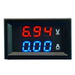
I have one or two of these http://www.ebay.com/itm/Dual-LED-DC-Digital-Display-Ammeter-Voltmeter-LCD-Panel-Amp-Volt-100A-100V-L5YG-/361449365620?hash=item54280fa074:g:eek:mUAAOSwRgJXhumn
voltamm.jpg
and was planning on using them for no frills current and voltage display, but am just realizing there is no adjustability to their current sense.

Apparently they want 0-75mV for a 0-100a scale because they use a .00075 ohm resistor.

How will that work with a motor controller's shunt measuring around 1mOhm???

I think I may need to add a trimpot somewhere, and maybe another resistor but I really haven't found the specifics to make me comfortable with the mod. . . .

Isn't there any cheap display that is already manually adjustable???
Thanks!
 
Well, the simplest thing to do if you have one of those or want to use that one is to get a shunt that is the value it needs, and put it in series with the battery wire just like the CA's shunt would be. ;)


However, if you want to use an existing shunt and need to down-adjust the voltage from it, you can look up (IIRC) Jeremy Harris' posts about tuning a shunt (sorry I can't remember waht thread it's in). It was a way to tap off the existing shunt and use either resistors and a pot, something simple like that and get a different voltage out--it was to deceive the controller as to how much current it was delivering, with more precision than just soldering the shunt.


What I'd use is one of the cheap RC wattmeters, as long as you're below 60v fully charged, things like the WattsUP and clones thereof like the Turnigy Wattmeter would all do the job as "accurately" as any of those panel meters, but also give you watts, wh, ah, etc.
 
On aliexpress.com you will have 10, 20, 50 A versions for less than 10 USD delivered.
I got 20 A.
You can make your own shunt by checking tables of resistance of wire vs diameter, but for a very accurate reading, you will need shunt with a little higher resistance than required and THEN solder in parallel extra wire/ wire pot for correction.
 
Thanks guys. Yes that would work WH. And it would have some more function than the cheaper 10$ 100v 100a meters w/shunt.

However, the CA doesn't need a big ass ugly shunt because it simply can be adjusted digitally to decipher readings from the controller shunt I think. So technically I think another display doesn't necessarily need another big shunt either?

I'm looking for one with a trimpot and the brain to adapt to the various controller shunts, just like CA seems to do digitally. Why have that ugly ext shunt if it's just a reduncancy in the system?


AW, I happened across a similar thread by JohnCR, about actually using a pot to temper the controller's readings of it's own shunt, simulating changes that led increase or decrease in amperage. That sounds awesome as a side note, but I just want to accurately monitor the controller shunt to a display same as CA does. Also, reading into spoofing the controller with a pot to change amperages, it sounds like a good way for me to really eff stuff up lol. I'm hesitant to even mod a shunt itself permanently for more amps.

But I think a pot inline somewhere is also a remedy/ right track for simply mating a 'dumb' display.
Will search for Harris's posts.

Just wish someone sold one (like CA), but without all the extra functions and size of the CA.
 
If it's made for a .75mohm shunt and you have 1mohm, then it would read high. This could easily be fixed by placing a trimmer pot as a voltage divider between the shunt and the meter. You would then need to calibrate it, but if the shunts are pretty precise, you could just do some math and set the pot at the needed resistance.
 
Well, they say it's in mV (75mV). I guess that can translate directly into mohm?

If so it would always be 33% high, right? (75mV display, 1 mohm shunt)

Regardless, if it's just a trimpot (probably put on the far end of shunt from ground?), and the light math it sounds perfectly doable.

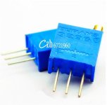
Would I need a specific resistance trimpot? Are there various ones that are better to solder up in-line, set, protect, and forget about?

Thanks!
 
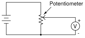
Nearly any value of pot will probably work here assuming the meter has a high input impedance. Use whatever's handy. 100 ohm to 100k ohm should be fine.
potentiometer-diagram.png

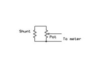
Have the shunt wires feeding the ends of the pot and the wiper and one side to the meter. The pot gets adjusted to feed 75% of whatever is going in.
 
Thanks for those points sir! I have some homework here so I faaa knuthing up; but it does sound simple!

////
Have the shunt wires feeding the ends of the pot
Ok got it. . .

and the wiper and one side to the meter.
I'm guess I'm not quite following the text or the diagram.

pot.jpg
Does this make sense? http://www.instructables.com/id/Wire-a-Potentiometer-as-a-Variable-Resistor/
Normally, potentiometers are wired as variable voltage dividers: connect +V to one side, connect the other side to ground, and the middle pin will output a voltage between 0 and +V (fig 2).
However, by only connecting two pins (one outside pin and one center pin) of a potentiometer to your circuit, you can turn a pot into a variable resistor. Think about it this way: the potentiometer is filled with resistive material and turning the knob changes the amount of this material that the electrons must travel through before leaving the pot. This means that the maximum resistance of this variable resistor is the total resistance of the pot. In figure 1 the pot has a total resistance of 10kOhms, so if the pot is turned all the way to the left the resistance between the two black wires is 10kOhms. If the pot is turned all the way to the right the amount of resistive material between the two black leads drops to zero and the resistance goes to zero as well. Any position in the middle will give a resistance between 0 and 10kOhms.
Does a side of the shunt sense also hit the center pin of pot (wiper?), and the other sense of shunt goes to the meter? What about the other side of meter sensing?

I'm sorry if this is obvious, I guess it's way beyond me.
 
OP, I have the same one on my ghetto laptop charger for my setup.
Volts are OK, but Amps are way off. Beware.
 
Edited///
Without even breaking open a controller . . . .

You [strike]could[/strike] CAN tap into an existing CA3 plug.
It's the white (S+) and blue (S-) to take to the pot, or just ammeter.


And the red and black on the plug will give pack voltage for a voltmeter.

And the 5v + and - from throttle or 3spd switch will power the volt/ammeter.

Polarity of S+ and S- DID matter when I tested without pot, to the meter.

This controller's shunt is around *(.071 ohm, so if the standard setting for the gauge is .075 ohm) it will only be off by about 5-6%. That might be livable if you don't have a pot handy.
http://www.ebay.com/itm/LED-Digital-Voltmeter-Ammeter-Amp-Volt-Meter-Current-Shunt-DC-100V-50A-Dual-/141455619876?hash=item20ef697724:g:8PMAAOSw-jhT~EZI This is the meter and wiring, although I have the cheap one without shunt. Using controller's shunt works well, and Fetcher has added how to easily correct shunt to any meter. Thanks!

Best of all, I blew nothing blew up! :lol:
* still a little confused of the scale. Both are about the same to the decimal place though, so percentage should be right.
 
Best thing would be to measure against another calibrated ammeter. If that's not an option, you could dial the pot to the calculated needed resistance before installing.
 
Well dang it, I measured good 5v and ground from the 3spd switch, wired everything up, and the meter doesn't power up and the 3spd switch goes to defualt setting. unplug those twp conductors from the meter and everything is fine. Run PS 5v and ground to the meter and it works.. . .

Guess it has to do with typical 3spd switch operation. I'm pretty sure I can switch over to throttle 5v and ground, and steal a little mv there. Out of friggin heatshrink though, lol- Oh the humanity! :lol:

Btw, the glue heatshrink is awesome, but I'm still not sure if people regularly even shrink their jst's.
Is it overkill to fill them with grease and use the glue heatshrink? It's not like your trying to bike thru the great salt sea or anything. . . :?
 
The meter might be drawing more than the little 5v regulator in the controller can handle. Those are typically only rated for 100mA and the controller is already using half that or more. You may need a separate 5v dc-dc converter.
 
On those I've worked on, 3speed switch doesn't have a 5v, just a ground and two signal lines that are pulled up to 5v thru a resistor. Put a load on that and it just grounds that signal line, telling the controller to switch to whatever mode that is programmed for.

There might be versions that use a 5v, and two signal lines pulled to ground thru a resistor instead, but the problem remains that there aren't two wires you can use for 5v and ground out of the switch.

The throttle will have that, though it's possible as Fechter noted that it may not be able to supply enough power to reliably operate both the meter and all the controller's 5v stuff.

If you have an unused phone charger, they're usually 5v and often will work fine off a 48v (55-60v fully charged) ebike pack, just wire main pack +/- to the wall prongs.
 
Right. Maybe try using the +5v from the throttle. Good if you know what the current draw of the meter is also.
 
I have it pulling from throttle now. After a few rides, the voltmeter part will flash from pack voltage to '100' (it has max 100a 100v). Not sure what the heck that is. A little more testing will hopefully show. I have an inkling it's only as pack voltage gets to a lower soc, although I don't see much logic behind that or why it would happen.

Without a 'max' memory, the ammeter part is just for a little reference and feels somewhat arbitrary. I know what the controller is set at, and (not in broad daylight with these meters) I can notice spikes during wot pretty close to that setting. .71 controller shunt and .75 mohms meter was close enough in this case.

Just got back from a few mile ride- my neighbor rode the huffy with 1kw yescom. I hit full draws (~6kw) and did some ripping, but mostly just stayed with him 25-30 on the road and trail. My bike is heavier, but he is heavier. I have 2.4" tires and huffy has 1.5 and 1.75.

The mantra has 11.6ah and ended w/ 3.83 avg cell. The huffy 1kw has 16ah and ended the same! From reading on here I new this parallel middrive was efficient, but wow I'm pretty surprised it kept up with 50% more capacity and 1/5 the draw. I guess more draw allows you to get to optimal rpm quicker, wasting less power. I'm guessing it was 6-7miles and some hills. About to map it out.
 
Those things are really hard to read in direct sunlight. A LCD version would be better.

Not sure why it would flash, but you might check the 5v and see if it is possibly dropping out.
 
Back
Top