could use some electrical help here, thanks...

ptd

100 W
Joined
Jun 15, 2011
Messages
196
Location
california
I have an ecospeed, 600 watt BMC, 48v20ah vpower battery, 48v35a infineon controller.

Got her all tightened down. All wired up. Took her out. Maiden voyage. She did ok for about a mile, nothing too crazy, I even pedaled most the way, full throttle only some of the time, some light ups and downs, two stops, no takeoffs on a grade. Then, taking off after the third stop, she kicked off. Motor was warm, controller was hot. First trip, first casualty. Got her home. Those 35 extra pounds make a pretty big difference in mountain country, but not too bad. Put her on the charger, 60v, 2 amp, it ran for 35 minutes. Hooked her back up, nothing.

When it first happened, I thought maybe something wrong with the battery (it's used). But since it charged so quick, I'm thinking controller. Any other possibilities? I've got a cheapo volt meter, and no idea how to use it (almost literally, lol). Where should I start?
 
Lots of possibilities, but I had something like that happen on a 6FET under heavy load at low speed, controller main cap overheated and failed. Replaced it and was ok. I think I replaced a couple of others just in case, but the main one was the known culprit.

There is a tutorial on adafruit / ladyada site on how to use a meter. ;)
 
thanks AW, ladyada worked. ok. i get 57.3v on the charged battery, which sounds right. curious, can i check the various groups of cells? through the BMS? it has a couple of JST looking connectors. or does the bms balance during charge? still might be worth checking out after a lvc tripping ride.

breaking into the controller and replacing FET's sounds challenging, but not impossible. especially after assembling a non hub drive. (and a quick youtube search yielding this)

[youtube]ieoM_40nRVs[/youtube]

ok, desoldering braid. i might have to give it a go. so, is the main cap something different? how do i test individual pieces? do i need some kind of schematic? or do i just break it open and look for the burnt ones? you mention having replaced a few, did you upgrade them? to kind of avoid a cascading failure kind of thing? (are they in a series configuration?) like, if the main cap wasn't the weak link anymore, what's the next thing that'd give out?

lastly, how do i avoid doing it again? i guess i'm wondering if the partial throttle was the culprit. and whether i should go WOT all the time, and pay lots more attention to which gear i'm in. my thinking in partial throttle was that i have a 35amp controller, and a 20amp battery, and was trying to take it easy on the battery. or is 1.75C even an issue? thanks again.
 
ptd said:
i get 57.3v on the charged battery, which sounds right. curious, can i check the various groups of cells? through the BMS? it has a couple of JST looking connectors. or does the bms balance during charge? still might be worth checking out after a lvc tripping ride.
57.3 sounds reasonable for a topped-off pack like that, similar to mine.
You can check cells via the methods here:
Volgood 48V20Ah LiFePO4 pack Repair
http://www.endless-sphere.com/forums/viewtopic.php?f=14&t=30864
and here:
VPower / CammyCC 48V20Ah LiFePO4 Repair
http://www.endless-sphere.com/forums/viewtopic.php?f=14&t=22750
If the pics aren't back up yet from the forum server transfer, well, maybe someone will eventually restore them from their backups.


breaking into the controller and replacing FET's sounds challenging, but not impossible. especially after assembling a non hub drive.
I doubt it's FETs; usually those would die suddenly and completely. Caps can start to act funny and then stop working. Though if caps go bad and the controller is then overworked, it is possible to blow FETs with voltage spikes the caps would've absorbed.

so, is the main cap something different?
It's one of the big can-shaped parts.

how do i test individual pieces? do i need some kind of schematic? or do i just break it open and look for the burnt ones?
Schematic would help, if one exists for your controller, or you can trace it out, but simply testing all the bigger caps in there will do the trick; there's only a handful. It does typically require desoldering them from the board to test, at least on one leg. Your meter also must have a capacitance tester mode that goes high enough in uF to test them, and most cheap meters do not go that high even if they have the mode.

In those cases, going by visual inspection or just plain replacing any that might be suspect is all you could do, but not until you ahve elminated all the other possibilities.

Visually, there is not usually anything you can see, except sometimes a "bulging" of the flat top end of the cap, sometimes it's more obvious because it's actually ruptured the score-mark on top and leaked. Google images of "leaky" or "blown" capacitor, or check places like badcaps.net and you'll see what I mean.


you mention having replaced a few, did you upgrade them? to kind of avoid a cascading failure kind of thing? (are they in a series configuration?) like, if the main cap wasn't the weak link anymore, what's the next thing that'd give out?
Lots of possible things in the system; take a look around at all the controller-troubleshooting threads and you'll see what I mean. :)

I put in the best ones I had that would fit, but they weren't much of an upgrade. :lol: If I had money to *order* better ones, I probably would have, though. Actually I'd probably use more of them, and larger, along with smaller paralleled ones, as discussed in a few controller development threads.

lastly, how do i avoid doing it again?
Depends on why it happened.
keeping the controller cool will help; finding out why it's getting hot would be a good idea. Keep an eye on your wattmeter to see what currents are being drawn in various gears and situations, then see about re-gearing things to lower the currents and still give you the performance you're after.

Force-ventilating the controller can help, too, with squirel-cage fans (radial flow) on one end, for instance, with vent holes on the other.

i guess i'm wondering if the partial throttle was the culprit. and whether i should go WOT all the time, and pay lots more attention to which gear i'm in. my thinking in partial throttle was that i have a 35amp controller, and a 20amp battery, and was trying to take it easy on the battery. or is 1.75C even an issue? thanks again.
I'm pretty sure that up to 2C is ok on those packs, but it will shorten their life if it were continuous. Thing is, a 35A controller just means it *can* suck that much from the pack, not that it *will*. You'd have to watch your wattmeter to see what current you are actually pulling at various loads with various gears, but typically even my direct drive hubmotor on CrazyBIke2 doesn't pull 40A for more than a few seconds, and goes down to less than 0.5C on the same type of pack you have after reaching speed.

With shiftable gears, you'd be able to keep it even lower and at higher currents for much less time, as long as you are in the right gear for startups and accelerations.

Partial throttle for me on the DayGlo Avenger setup was mostly trying to conserve battery and keep from hammering the poor NiMH so hard; I would ahve been better off to just ease up to speed and then WOT from there.

When your controller is in current-limiting it will do the same thing as not being in WOT, anyway, so you can do WOT all the time with the right gearing and keep current down without worrying about the other problems.
 
Since it didn't start working again after a charge, I don't suspect the battery so much. But that is a lot of controller for that type of battery.

The controller being so hot definitely points that direction. It just doesn't sound like you abused it enough to cause that big a problem. I'm wondering if you had the correct phase order. Did it seem to run well? Since the motor was not hot, I doubt that was it, but it's possilbe.

It could be as simple as what I always say check first, bad connections or cut wiring. Backed out contacts from the halls plug is common, followed by bad plugs on throttles, or anything else.

But it could be just bad QC on some item in the controller or motor, like a hall sensor died in the motor immediately.
 
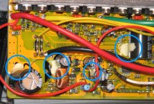
I didn't suspect the battery either, but more because of the 57 volts. Although, in hindsight, it would have been nice to have gotten some measurements of the individual 'strings', before I charged her back up. The links to AW's post don't have the attachments anymore. Not yet, anyways. Methods actually suggested a 40amp controller, and to just take it easy, so I figured 35amp was even less of a risk. I've taken the controller off, unscrewed the 13 screws, and slid out the board. I looked at the site AW posted, and most of the cap failures look like bulged or split endcaps. Not the case on mine, but I do have some light beige material on the sides of a few of them. Both big ones, and a couple of the small ones. Don't know if it's innards. Here's the photo.

controller2.jpg
As for running, when I first put it together, it ran kinda rough. It would only 'catch' some of the time, as in, I could hear it running, but it would rarely engage the drive sprocket. So I cut off the JST connectors, and crimped on 18-22 bullet connectors. And then matched color for color (suprisingly enough, the jst's male and female didn't have the same wiring order). With color for color, it engaged all the time, enough to spin the wheel up nicely, while held off the ground. I took that as a good sign. Silly me, lol. When I tried to ride it like that (and only with the same little blips of the throttle), it wouldn't engage. So I decided to experiment with the halls. On the third try, (where none of the three colors match up, no less), she was quite torquey. I took THIS as a good sign.

As for the ride, I was pretty cautious with it. Full throttle for only a few seconds at a time, then partial once I was at speed. No big inclines, couple of slight ones, but only for about a block at a time. Again, pedaled lightly to moderately, most of the way.

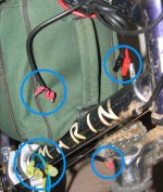
The connectors 'could' be a problem. The throttle and halls are even smaller gauge than 22 methinks. I realized that going in, so I stripped the wire back a bit more than needed, and doubled it up, before inserting into the connectors. I also used a regular 'pinching' crimper, not the 'toothed' kind. I wouldn't be surprised if something just got a little loose. I may have to try that first, better crimping all the way around. I don't have any cut wires, the layout is quite compact. Here's a photo.

wiring.jpg
I also thought it could be something in the BMS. This made me hook it up and check the voltage at IT'S output, and it was the same, or only off by .1 volt. Unfortunately, no watt meter. Yet.

With my limited experience, I think the motor is the weak link. It's only 600 watts. The battery is 960 watts. Seems to me the controller should have been able to handle these guys no sweat. Using justins program (i know it's for hubs, but i didn't do much gear changing), it looks like the controller would have only been taking 1400 watts max from the battery, and putting out 1000 watts max to the motor. Is it possible that it might have been defective in some way?

Lastly, is there some way to check the halls without getting into the motor? Like some kind of continuity check?
 
It is not very common for hall and phase colors to match up between motor and controller, so it is totally unsurprising that they started out unmatched. If the motor functioned as it was supposed to with the original color pattern, I highly recommend using that, but otherwise testing all combinations and watching the no-load (wheel off-ground) current at low throttle each time should help you find the right combination.

Even if you have to use the 10A function on your multimeter to do the current testing, you should still do the no-load current test on the motor for wire-order determination. You can have a positive match that appears to work but draws WAY more power than it should, and can overheat motor and controller (and eventually damage things from that heat) while under load.

Normally it's probably less than 1A, maybe 2A, no load on motor, depending on it's type and the drive system it's hooked to.


The caps on yours look normal, and the white stuff is just glue to keep them from vibrating around and either damaging other components or having their legs fracture and break off, disconnecting them from their function in the controller.

Nothing else obvious either.

The caps could still be bad (usually the largest ones; I forget which one was bad on mine but it should be noted in the DayGlo Avenger thread, even if the pic doesn't work), but the only way to find out is to either test them or replace them with known good ones.

It could be totally unrelated, too, and maybe there is a broken wire inside the insulation, or a bad crimp that got wet and then oxidized. Lots of possiblities, but have to narrow them down by elimination and by symptomatic troubleshooting.

There's a few threads discussing testing halls in various ways, some with nifty testers designed for the purpose, and some with DIY hacked methods, some with just the existing controller hooked up and turned on, and hand-rotating the wheel.
 
ok, got some real crimpers. crimped everything nice and tight. still no power. battery checks out fine, bms is throughputting as well. nothing got wet. no response from cycle9 yet. this bites. the grin is fading.
 
AFAIK, Cycle9 is going or already went out of business, recently, at least for their physical store. I dunno about the website version; it says that a website will stay up, here:
http://www.cycle9.com/blog/cycle-9-retail-shop-closing-doors/
but I imagine that just means the blog, because there isn't much available on the webstore anymore; just one accessory (side flag) and a couple clearance chargers. Don't know if they are still providing support or not.


If the battery is getting power to the controller at the proper voltage, and the controller's "keyswitch" or "ignition" wire is connected, but there is zero throttle response, does the current draw from the controller increase when throttle is increased?

If so, the phases or halls are probably not in the right order. If there's no change in current, the controller itself may have a problem.
 
kristen told me it was just the physical store that was closing, but that could have been a line.
i don't have a CA or a watt meter, so i'm not sure how i'd check draw, as in, where would i attach a volt meter? and do i switch it to the 10A setting? the wiring is in the same order as it was when it was running. and zero throttle response.
 
I'm still voting on a broken or shorted wire. If the battery is reading 50+ volts and the motor doesn't even turn 1/4 refolution I'm pretty sure you don't have a battery problem.

A controller getting hot does not really indicate that it is the controller that is broken. They are supposed to get warm/hot, that's why they are a giant heatsink. How many seconds could you hold your finger on the controller without burning yourself / having to pull away?
 
Regarding colors vs working, remember I said that you can have a postive match that appears to work but draws too much power? That's very possibly what happened, and that could have damaged something from the heat.

To test current with the meter (which somehow isn't in the LadyAda tutorial :?) you place the black lead of the meter in it's COM or black hole, and the red lead in the 10A hole, and set it to the 10A setting.

Put the black lead on the positive main power pin of the controller, and the red lead on the postive main power pin of the battery output. Connect the negative main power leads of the controller and battery together (if you only have one multipin connector and not somethign like andersons or bullets, you may have to use a jumper wire or alligator clips).

If everything is hooked up and working, there will be a small current draw, probably less than 0.1A, maybe 0.05A, but there should be *some* above 0.00A.

When you then very lightly engage the throttle just a little bit, with the wheel off the ground, there should be a current change. If it's really high, more than a few amps, there is probably something wrong either in the controller (damage) or the wiring to the motor is wrong.
 
el_walto said:
I'm still voting on a broken or shorted wire. If the battery is reading 50+ volts and the motor doesn't even turn 1/4 refolution I'm pretty sure you don't have a battery problem. How many seconds could you hold your finger on the controller without burning yourself / having to pull away?
the battery actually goes to 58.4 volts now. the motor doesn't turn at all. and i could have kept my hand on it for probably 5 seconds, dunno. i like the idea of the broken wire. seems like it would be a lot easier to test, and repair. any suggestions on where to start? i'm thinking throttle. so i hate to sound like the noob that i am, but how do i do that? my guess is to power the red, ground the black, and then twist the throttle and look for a signal on the third white wire? somehow? is there a thread somewhere for diagnosis procedures? or maybe just a really detailed explanation of controller functions? for dummies? or maybe just noobs? lol

ok, maybe i should also mention that my throttle has 4 wires, only 3 of which i'm using, going into the controller. is that bad? i had figured the fourth was just for the power level lights on the throttle. and considering it did work, even if for just a short while, it's hard to imagine that it was wired up wrong. but i could easily be wrong about something.
 
I'd hazard a guess that you have miss wired the halls and phase wires.

Before you do anything else listen to AW and test all the other color combinations (all 36). If you can't get the motor to spin you will then need to check the halls and check the phase wires for shorts. If you can get it to spin, then you need to check the amp draw when the wheel is off the ground.
 
amberwolf said:
Put the black lead on the positive main power pin of the controller, and the red lead on the postive main power pin of the battery output. Connect the negative main power leads of the controller and battery together (if you only have one multipin connector and not somethign like andersons or bullets, you may have to use a jumper wire or alligator clips).

If everything is hooked up and working, there will be a small current draw, probably less than 0.1A, maybe 0.05A, but there should be *some* above 0.00A.

When you then very lightly engage the throttle just a little bit, with the wheel off the ground, there should be a current change. If it's really high, more than a few amps, there is probably something wrong either in the controller (damage) or the wiring to the motor is wrong.
ok, back at it. i don't have andersons, anymore. but the big yellow connectors seem quite amenable to the static voltage test. i can just insert the leads into the backside of the connectors. i'm still a little confused about the procedure. ie, 'main power pin of the controller'. do you just mean the controller input (presumably red) ? or one of the output phase wires (B/Y/G) ? or is it a thing where you disconnect the the positive connector (between the BMS and the controller ?), and use the meter as a bridge ?

as for the pre testing, i got the spreadsheet, and it appears that cycling through just the hall wire combinations will result in SOMETHING, at least once, out of 6 times, and i got nothing with any of them. my thought is, considering the combination i had originally, it al least powered up, so i think there's something wrong with the controller (or the throttle, although i think that's a little optimistic). if that's the case, what is it that would have blown, given a possible miswiring ? and should i be testing the throttle somehow ? like, switch the meter down to the 20v setting (don't they run on like 5v ?), attach the leads (to which wires ?), turn the controller on and blip the throttle ? or is it possible that a failure on the board could prevent it even getting power ? if that's the case, do i first try connecting the meter to the positive and negative connectors of the throttle? turn the controller on and see if i'm even getting the 5v ? and if i do, which lead do i then disco, and attach to the signal wire ?
 
nicobie said:
If you can't get the motor to spin you will then need to check the halls and check the phase wires for shorts.
ok, did all 36 combinations, and as expected, nothing. so how do i go about testing for shorts? and testing the throttle? and testing the controller? i get the feeling that it is the 'bridge' method for the controller, but can i just insert the leads into the backs of the connectors? or do i need to disco both wires, connect the red lead to the to the positive coming out of the battery (are these the 'main power pins' you're talking about AW?), the black lead to the positive going into the controller, and then connect the negatives?
 
hello, hello, hello... is there anybody out there... just type if you can hear me now...
 
Sorry about the long wait; there are just too many things going on lately. :( Can't even finish my own stuff (but that is not new).

The fourth wire in the throttle connector is only used for it's battery meter. If it worked before, that's not the problem.

But you can use it to help troulbeshoot, if it is made for the voltage of battery you are using. I would wire up a temporary wire, at least, from that meter wire to the controller positive power wire. Then you will know if you are getting voltage to the controller or not, *and* you can use it to watch for battery sag or cutout, both while testing and later on the road.

If youc an't use that meter for some reason, then use your multimeter set to V, with the red lead into the *back* of the controller's main positive power connector to the battery, and the black lead into the controllers' main negatie power connector to the battery. Do this on the controller side of the connector, to be sure it's reaching the controller.

To be doubly sure, you could take two safety pins, and push the pin thru the insulation of your controller's battery power wires, ensuring you don't short the safety pins to each other or anything else. Then touch the safety pins with your multimeter leads. That tests what you get at the *wires*, whcih is a better test than what you get at the connector pins. Again, it has to be on the controller side of the connectors.

If you get normal battery voltage, then turn on the bike/controller, if it isn't already, and see if it stays that way.

If you get no battery voltae or a lower voltage than you get at the battery end, you have a connector problem, or a wire broken inside the insulation.


To test current draw:

The main power pins I'm referring to in previous posts are the ones from battery to controller. To test the current draw during the phase/hall tests, without a CA or other wattmeter, you need to insert your multimeter, in 10A mode (if it has one, if not, post what it does have to see if this can be done with it at all), between the positive of the battery wire and the postiive of the controller wire.

I assume that if you dont' have andersons, you are using the same automotive spade style connectors that are on your phases for your battery wires. If so, simply leave the negatives plugge din normaly, and disconnect only the postives.

Put the black meter lead from meter common jack to the battery positive.

Put the red meter lead from meter 10A jack (it is usually separate from the regular V/ohms jack) to the controller positive.

Make sure both are connected well; this may be difficult because you're not going to be able to hold them by hand while you do the rest of this test. If you have spare banana plugs, and spare spade lugs and some spare wire, you can make test leads specifically for this, to use in place of your meter leads. But you won't need those very often (hopefully only this time), so they might not be worth making.

Make sure the meter is set to it's 10A mode.

Set up the bike so it's motor wheel is off the ground.

Power on the bike, if it isnt' already.

The multimeter should register some current, maybe 0.1A or less. If there is no current registered at all, it's possible there is a connection problem with the meter leads to the power leads at controller or battery, or that the problem is within the bike stuff.

Very slowly move the throttle up from zero to just enough the motor would normally begin spinning, watching the multimeter the whole time. It should register more current, up to a couple of A or more, if the wheel were moving, or even if the phase coils are getting current flow from the controller but not moving.

If nothing at all happens, no current, again it could be the meter connections, or the controller could be dead, or a connection in the bike harness, etc. If the current reading is very high even at tiny throttles, something else is wrong (possibly the phase or hall order).


You can test the halls individually, too, to see if they are getting power from the controller, and that they are outputting the right signals, either with your meter or with a DIY tester. There are at least a couple of those described and shown in threads on ES, so youc an build one if you want. It's easy enough, or you can buy one from Lyen (which will test other things on teh bike, too).

Same thing with the throttle--you can test it to see if it is actually even doing anything when you move it. Reember that it won't output 5V, but rather just a small range of voltage somewhere between 0V and 5V; though you should get 0V on the ground wire and 5V on the postive wire.


It is still very possible that your original combination that appeared to work was too high a current draw, and damaged something in either controller or motor from the resultant heat.
 
hey ptd, how's it going?

After amberwolf's tests above the next thing I would check if I were you is the throttle... The throttle typically has three wires or maybe 4. They are:
1. Ground
2. +5V Power
3. Speed Control back from throttle to controller
4. (sometimes) battery voltage for bat level light

So maybe you have a wonky connector, or a loose wire that worked its way out of the crimp. Double-check. And if not, figure out how you can touch your meter probes to the throttle connector wires, carefully, without shorting them to each other. (See other posts in this thread for tips).

Now with the controller powered on, the first thing you can check (meter in Volts mode) is whether you have 5V between Gnd and +5V... If so good, the throttle is getting power at least. Next, as you turn the throttle, you should see a changing voltage between Gnd and Speed Control wires, from about 1V to 4V as you turn the throttle. If this works, then you are also getting a throttle signal to the controller.

Next thing I'd check is good connections from the controller to the hall sensors on the motor. And again maybe you just have a wonky connector or a wire that worked its way out. If nothing obvious, check that when the controller is on, you should be getting +5V from ground to hall-power (usually Gnd is a small black wire and hall power is a small red wire from the controller to the wheel)...

I don't know if anyone has suggested it yet but also, ES forum member Lyen sometimes sells an inexpensive motor + controller tester that also might help you narrow down whether the problem is on the controller or the motor side... Good luck!
 
Back
Top