Cycle Analyst V3 preview and first beta release

ashwright said:
Can the Aux input be used to control max throttle out?
Yes. I am presently using the Vaux input to provide three power levels using current limiting (Ctrl->AuxFunct = AmpsLim). I have a little post with an Excel resistor calculator that will go up shortly to illustrate this using an off-the-shelf Crystalyte LMH switch.

ashwright said:
I am trying to think of a way of using the new CA, to control the performance of a PAS, mid mount bike. So you can use the three way switch on the handle bars to say, Pedestrian mode (10%, 5kph, very slow accell), bike mode (70%, 30kph, medium accell) and road mode (100%, fast accell).

My current bike has a PAS controller, with a three way switch, which seems to have this behaviour. But most newer good controllers don't have this, and it looks like the new CA would be perfect, with a basic, cheap, high performance controller.

Would there be any other way of using the CA in this way?
Justin will need to verify, but it appears that there is mode that will do exactly what you want with Ctrl->AuxFunct = PasLevel. If you check the Setup summary, you can see two other associated parameters (Ctrl->PASMode and Ctrl->AssistLevel) that appear to determine operation at the 100% value for the POT pad (Vaux) on the CA PCB.

As with Ctrl->AuxFunct set to any of the other possible control modes, it remains only to use a resistor divider to obtain a couple of lower percentage values of the voltage range Ctrl->MinAuxIn to Ctrl->MaxAuxIn and to select one of these fixed voltages with a switch. One possible configuration might use a SPDT on-off-on switch arranged like this:
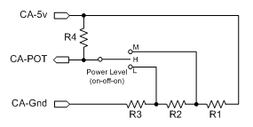
CA_v3_LMH_fixedR.gif
 
Thanks Teklektik;

I'll give that a try today. It isn't like limiting at all it'a complete cutoff..

On another note why doesn't setting the throttle to pass-thru or disabled bypass this problem? It would be great if one of these modes was just a limp home diagnostic type bypass or pass through. So that what came in the throttle input went out the throttle output exactly with no transformation limiting or compensation.

I didn't find out about my current problem till I rode down a really big hill. Would have been great to have been able to set to pass thru and have it just ignore whatever setting it is that's wrong and just get me home. The drive by wire throttle needs a work around at least for me. If I smash the CA off on a tree or something It would be game over for propulsion. I think I'll add a micro size switch and do a hard bypass for the one signal line involved.

I'll report back on the changed settings. I'll try and turn every feature down or off one at a time and alter every parameter. The hard part is I have to go up the hill everytime to test it as it won't do it on the stand.

I'll let you know
 
lizardboy said:
I'll give that a try today. It isn't like limiting at all it's a complete cutoff...
The idea is not to go into this with a preconceived notion of how it will fail or behave regardless of the names of the parameters - just to gather some information for Justin that involves the smallest number of interacting control features as possible. If this first test works fine, you can add in ramping, etc one at a time until you have a clear "I did this and suddenly it misbehaved". This may help localize the issue whether it's code or our (mis)understanding of parameter interactions that he can clarify.

lizardboy said:
On another note why doesn't setting the throttle to pass-thru or disabled bypass this problem?
ThrI->CntrlMode = Pass-thru bypasses the closed-loop throttle feedback logic utilized by ThrI->CntrlMode = {Current|Speed} modes so you are running in open-loop mode - pretty much what goes in, goes out without embellishment save for ramping (and throttle voltage scaling). I believe that with ramping disabled, there should be no effects on the throttle save for the max limiting parameters (amps, watts, speed) much like v2.23. When I make these settings, the v3 behaves identically to the old unit.

lizardboy said:
It would be great if one of these modes was just a limp home diagnostic type bypass or pass through. ... The drive by wire throttle needs a work around at least for me. If I smash the CA off on a tree or something It would be game over for propulsion. I think I'll add a micro size switch and do a hard bypass for the one signal line involved.
I had the same concern about a single point of failure and so added a second JST3 connector under the dashboard that runs my controllers directly as originally intended. All three throttle connections (Gnd, +5, Sense) are sourced from the controllers - nothing from the CA. The normal CA-throttle JST3 gets its three connections from the associated pads on the CA PCB instead. Eliminating common connections avoids ground loops and allows the CA to be completely unplugged/removed without affecting the backup mode e.g. 'tree smash'.
 
lizardboy said:
It isn't like limiting at all it's a complete cutoff...
Rain finally stopped and I only had limited time yesterday before dark to try v3b13 - worked okay. It's sunny today so I'm doing more tests.

But - I am experiencing the same failure mode with the throttle cutout using ThrI->CntrlMode = Current. The symptoms come and go. I can get into a state where it works perfectly, then get into a state where it cuts out abruptly.
...
More tests, etc, but I thought I'd get this posted so lizardboy would know he has company :D

EDIT-

Justin-

Tests were all done heading up a hill with two BMC V2S motors, 66v20Ah Headway, 2 12FET Xlyte analog controllers, and Ctrl->AuxFunct = AmpsLim with Vaux set to 3.0v (3.0v/5.0v = 60% of Plim->MaxCurrent = 50 A yielding an effective MaxCurrent = 30 A).

After a bit more testing, it appears that the surging/cutout failure lizardboy reported is random on power-up making this look like an uninitialized variable. If it does start in the failure mode where it is surging badly (cutting out, zipping fwd, ...), I seem to be able to get it out of that mode by running down a short incline giving it throttle so the surging stops and all runs okay in the downhill. Then I cut the throttle to zero, stop, and the symptoms stay gone until another power cycle occurs. There is no CA button-pushing whatsoever between working perfectly, power cycling the bike, and having the failure (possibly) re-occur. I didn't test other action sequences beyond the roll/throttle/stop sequence - that magic works consistently, so I left it at that... it seemed that once it was heading downhill and it was able to achieve control w/o overshoot, it got the ability to do so in any situation.

Once the CA is happy and running properly, my ramping parameters seem to work properly which leads me to believe that the surging I saw with them previously was related to this other issue (just a guess). I didn't do very much with the ramping beyond seeing that non-999 values did not precipitate surging.

Here's my setup: View attachment CA_vB13a_ConfigSettings_teklektik_20120506_1510.zip
 
Well it is good to know I'm not alone;

My enviroment is all hills so I may have run into this a bit sooner than other people. Not trying to have preconcieved ideas here. But I'm an out of the box thinker in troubleshooting and I tend to follow a different pattern to other people. My understanding of how the CA works is evolving as we go. Seems exactly like a variable being initiated twice.

You'll notice that the voltmeter stuff I was talking about earlier only happens when the random variable problem comes up. reset like five times and the voltmeter drops the 0.2 volts(for me) that I expect for the calibration value and then the current throttle works no problem until you cycle the power.

Should be a simple fix I'm so glad you stayed on this... Takes a bit of hill to occur. Thanks for the tip about the ramp values I was decreasing the ramp value to shorten the ramp as this seemed logical but it's the other way around. Love that feature and the current throttle. My motor will last eons longer this way. I can ease on the power instead of every throtlle change being a full power speed change.

Now on to temp sensing, Did a few massive climbs of almost 2000 feet of vert. today Motor was fine but the controller was hot so I may start by sensing the controller. It's kind of the mine canary in my system The weather has been stellar today already came home and charged up again 4 times.

Because I wired my throttle using 2 wires out of the DP bundle. one to send the throttle signal to the CA and one to take it back I'm just going to mount the hard switch on the end cover of the controller. Easy bypass one hole required to mount the switch.
 
I have just been catching up on this thread and the cutting out problems others are experiencing, mine is currently running in current mode with the ramp up set to 100, everything is working well except i can turn it on and off 5 times and see several different voltages for the main pack on the main screen, as much as .4v difference, sometimes i get a blip from the motor on start up too and also when the reset is pressed. when a different voltage is displayed on the main screen the min in and min out preset voltages also change a little, it occured to me that this maybe related to the cutting out some are experiencing, when the throttle voltage settings change if they are set very close to the controllers starting voltage it could trigger the over ride to prevent an open throttle start? ie; if the throttle output voltage is above the controllers start point on start up the controller will not activate the motor, closing the throttle to reduce the voltage below the controllers min activation voltage will reset it, just a thought chaps, lower your min output voltage a little more to see if this is your problem.

Simon.
 
With the cutout/surge issue identified and a solution in hand to get out of that mode, I moved on to other experiments and testing today. The bike was configured for current throttle, power (Watt) limiting, and used both up and down ramping. The Vaux input was configured as a three level LMH power limiting (Watt) selector. Unlike v3B12 where I could not get Power Limiting to work even with WGain=1, v3B13 works pretty well although I cannot use values above WGain=15 without getting dramatic surging from a dead stop.

Settings:View attachment CA_vB13a_ConfigSettings_teklektik_20120507_1720.pdf
Tweaking complete, I went for a 25 mile ride with minimal pedaling. This was one of my usual trips with speeds varying from 12mph to 40mph - part rolling hilly roads, part paved bike paths.

Once I got it out of the initial power-up cutoff/surge mode, the bike ran very well for the remainder of the ride. Startups were smooth and the power limiting worked very slick delivering the prescribed power levels even with battery sag due to discharge or heavy two motor loads. Switching the Vaux levels on the fly worked smoothly with no appreciable delays as new higher/lower power levels took effect.

I had some very minimal 'hunting' on getaways but additional WGain adjustments should address that. Although I could not feel it, there were some rapid power oscillations visible on the CA Main Display in certain circumstances as the CA attempted to home in on a target power level while underway climbing hills - the average power came out okay, and the hunting was rapid enough that there was no rider sensation of the action. This may be related to running at Vaux power levels different than the one used to tweak the WGain setting. Again, this was an observation of CA displayed values, but the ride itself was fine. Some additional WGain adjustment may lessen this effect.

Someplace in the middle of the ride, I switched back to Pass-thru Throttle because the Current Throttle was coming on too strong and I could not feather it to re-engage the load while rolling - (although it worked well from a dead stop). This is related to the planned but as yet unimplemented logic allowing the CA to accomplish more gentle re-engagements at speed. Until that feature appears, manual control (for me) offers less stress on the gear motors.

I need to test Speed Limiting, but that will need to wait until after the next few days of rain.

Meanwhile, the unit is running well with the exception of the cutout/surge bug and perhaps the low WGain scaling (015). The rider experience on getaways is much improved over v2.23 and the Power Limiting in lieu of Current Limiting keeps the bike peppy and responsive right up until max DOD is reached. The new ThrI->FaultVolt feature to auto-shutdown on open (runaway) throttle works very nicely and is a welcome addition. The earlier issue with throttle burp on Reset has not re-occurred.
 
Justin-

Although this would affect a noteworthy change in the operator interface over earlier versions, I would really recommend switching the top-level button functionality so that the left button invokes Reset and the right button invokes Setup. With only minor exception, the entirety of the Setup procedure utilizes the right button and it seems counter-intuitive to use the left button to initiate the Setup procedure then to rely on the other button to actually carry out all the configuration tasks.

...I have accidentally Reset my CA many times this last week while trying to reconfigure a parameter... :oops:
 
For me it's that I can't see the ok when it comes up because my right hand is blocking just a bit of that edge of the screen but not a big deal just have to get used to a new hand position.

Just to confirm the battery gauge only works when the throttle is released and shows full all other times correct? It also seems to hardly move only losing a few pixels by halfway discharged then catches up rapidly on the bottom part of the discharge curve. So far it's way better to just do the math in my head and subtract total ah from consumed a./h could be because I'm still running the emailed version as the posted version is useless for me currently. But if there is still work to do there I understand and I'll be patient. But otherwise I'd just like it to be run by the A/H totals cause thats what I'm doing when I look down anyway and I'm not sure what the advantages are for going with some other system. ROde my pack dead on a big uphill last night and the gauge didn't move from 7/8's full till the last 200 yards when the battery died (then it showed empty).

I've also forgotten to reset (many times wish that was automatic somehow) and even after running to 150% of what the pack capacity should have been the battery gauge still told me I had 7/8's of a tank. So clearly it's not looking at ah anymore. Maybe internal resistance is set wrong. I used my icharger's built in special function to measure the pack resistance. Is this wrong?

And also maybe I'm missing it but the second screen used to have a spot that showed the amps , I set the main screen to watts and I'd like to check the amps without having to change any settings. Is one of the realtime values amps? or am I just missing the screen that shows amps? I'd really love to have the first screen the way it is although I'd like the throttle slider to be switchable to show me what the output of the throttle is. and I'd like the second screen to show me everything else I need while riding like.... the temperature readings and the amp draw and maybe an estimate of distance left at the current wh/km sort of two screens easy to flip through. And how about an adjustable time setting that would default back to the main screen after a set amount of time. It would save having to have your eyes off the road to return to the main screen.
 
Special Considerations When Using Resistive (Magura) Throttles

The v3B13 Release Notes call out a new safety feature:

g) Adds a throttle fault voltage that you can set a bit higher than Max Throttle to shut the system down if you have a break in the throttle ground wire
This feature is implemented as a new Setup parameter ThrI->FaultVolt which has an allowable range of 0.00-4.99v and which cannot be set outside that range. This parameter is intended to be set slightly above the maximum input voltage set by ThrI->MaxInput. However, for resistive throttles such as the Magura, ViMax is already at or very near 4.99v making a higher setting for ThrI->FaultVolt problematic e.g. typical measured (ViMin,ViMax) = (0.00,4.95). Setting ThrI->MaxInput to an artificially lower value is ineffective since the actual measured sense voltage (ViMax) remains unchanged. Also, since ThrI->FaultVolt cannot be set higher than 4.99v, it is not possible to deactivate the auto-shutdown feature.

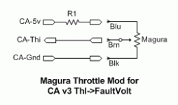
A simple workaround is to introduce a small resistor as shown below to slightly reduce the actual max throttle voltage. Loss of the Gnd connection will still raise the CA-Thi input to approximately 5v. Figuring a small safety margin of 10% (5% above and below ThI->FaultVolt) and a nominal Magura resistance of 5K, a 470 ohm resistor is suitable. This value is arbitrary; use any resistor 470ohm-3.3K to keep ViMax > 3 volts. Since the throttle range of motion will still deliver the full configured ThrI->MinInput to ThrI->MaxInput range, normal throttle operation is unaffected.

The resistor can be soldered directly to the (+5v) pad adjacent to the Thi pad of the CA PCB in-line with the (+5v) lead of the throttle cable and then entirely sleeved with heat shrink.

maguraThrottleMod.gif
Configure the throttle as outlined in the Setup notes. For instance, with R1=470 ohm, a typical measured (ViMin,ViMax) = (0.00,4.55) so ThI->(MinInput,MaxInput,FaultVolt) might be set to (0.10,4.45,4.80).
 
lizardboy said:
I've also forgotten to reset (many times wish that was automatic somehow) and even after running to 150% of what the pack capacity should have been the battery gauge still told me I had 7/8's of a tank. So clearly it's not looking at ah anymore.

Right now it's not looking at Ah _at all_, it's just a look-up table based on the extrapolated open circuit voltage. So with RBatt set correctly it's pretty good with LiMn and LiPo, but fairly useless with LiFePO4. I was hoping that the prototype code that I had talked about in the first page description would have been totally flushed out by now into something I could include, but it's not there yet. For each chemistry I need a whole set of lookup tables describing how much "confidence" to put in the open circuit voltage data vs. the accumulated Ah data, and it's gonna take some analysis time to work out.

And also maybe I'm missing it but the second screen used to have a spot that showed the amps , I set the main screen to watts and I'd like to check the amps without having to change any settings. Is one of the realtime values amps? or am I just missing the screen that shows amps?

There are a number of screens that are currently hidden including the all electrical screen2. Next beta firmware will have in the "display" setup options the ability to select which screens show up when you are moving, and which ones show up only when you are stopped. That way you can pick and choose so that while biking you don't have to push the button a bunch of times to see what you want, but when stopped you still have the ability to look at everything. If you pick a screen only visible when stopped and then start riding, it will stay on there until you scroll away from it.

And how about an adjustable time setting that would default back to the main screen after a set amount of time. It would save having to have your eyes off the road to return to the main screen.

Yes. And that too!

-Justin
 
Tench said:
everything is working well except i can turn it on and off 5 times and see several different voltages for the main pack on the main screen, as much as .4v difference,
Simon.

This is really curious and thanks you guys for noticing this, we definitely missed catching it internally. I've been able to verify a similar phenomenon on my bench unit but only to the tune of 0.2 to 0.3V. So on boot-up it might be 49.8V, or 50.0V, and which ever it boots into it seems to stay at that value pretty steadily as long as it stays powered on. That's an odd, and potentially fun, one to figure out. -Justin
 
teklektik said:
Unlike v3B12 where I could not get Power Limiting to work even with WGain=1, v3B13 works pretty well although I cannot use values above WGain=15 without getting dramatic surging from a dead stop.

Interesting, I found on our test ebike (9C motor with 48V pack and 25A controller) that a value of about 50 did a good job. However, a lot of the infineon controllers have a very annoying discretization of the throttle input signal which is especially pronounced at low speeds. So they will jump from like 3% PWM to 10% PWM but nothing in between, and this makes anything trying to run with feedback at low speeds / dead stop really problematic.

I need to test Speed Limiting, but that will need to wait until after the next few days of rain.

So the speed limiting now has a differential gain term, which is initially defaulted to a low value of 2 just to be out of the way. I have not yet had time to play with this and find the ratio of values that gives smooth speed control without overshoot. I'm hoping that it's a lot better than just the PI controller, but from what quick tests I did it wasn't too apparent.

Justin-
Although this would affect a noteworthy change in the operator interface over earlier versions, I would really recommend switching the top-level button functionality so that the left button invokes Reset and the right button invokes Setup. With only minor exception, the entirety of the Setup procedure utilizes the right button and it seems counter-intuitive to use the left button to initiate the Setup procedure then to rely on the other button to actually carry out all the configuration tasks.

Hmm, sometimes a more removed vantage point is needed to see the big picture like this. I think you are completely correct Teklektic! The current interface evolved from a 1 button design, and for various reasons it made sense that that 1 button became the right button, and where holding the 1 button used to invoke a reset so too would holding the right button. But wow, it makes way more sense that a left hold is a reset and a right hold (go to next screen, but DEEPER into the next screens) would be to enter setup. Totally concur.

The v3B13 Release Notes call out a new safety feature:
g) Adds a throttle fault voltage that you can set a bit higher than Max Throttle to shut the system down if you have a break in the throttle ground wire
This feature is implemented as a new Setup parameter ThrI->FaultVolt which has an allowable range of 0.00-4.99v and which cannot be set outside that range. This parameter is intended to be set slightly above the maximum input voltage set by ThrI->MaxInput. However, for resistive throttles such as the Magura, ViMax is already at or very near 4.99v making a higher setting for ThrI->FaultVolt problematic

That is a very good point, I hadn't really put thought into resistive throttles when implementing it. The way that the variables are stored I can't let the code save a value higher than 4.99V, so I'll put in list that if this gets set to 0.00V then it will disable the throttle over-voltage. Either that, or a "enable/disable" option for the throttle overvoltage fault protection.

That said, from a safety perspective it's a good idea to do as Teklektik suggests and use the fault protection and include a resistor inline with the 5V side of the throttle, so that if you do have a break in the throttle ground return it won't cause full power.

-Justin
 
Can anyone tell me which way to adjust [Rbatt] to make the fuel gauge (battery icon) go down quicker, i am going to keep adjusting it manually rather than use the actual IR so that it works over an 80% DOD instead.

Simon.
 
Tench said:
Can anyone tell me which way to adjust [Rbatt] to make the fuel gauge (battery icon) go down quicker, i am going to keep adjusting it manually rather than use the actual IR so that it works over an 80% DOD instead.

Simon, it doesn't work that way. The RBatt term when properly adjusted simply makes it so that the battery icon doesn't move up or down when load currents or regen currents change the apparent pack voltage. If you are running LiFePO4 just ignore the fuel gauge until the Ah accumulation is integrated in the beta software here.
 
Thank you Justin, i am running lipo, 18s 16ah, yesterday i used 10.5ah and the gauge was still showing 3/4 full so i wanted to adjust it so that using that amount of my battery would display the battery as 2/3 used.
 
justin_le said:
teklektik said:
Unlike v3B12 where I could not get Power Limiting to work even with WGain=1, v3B13 works pretty well although I cannot use values above WGain=15 without getting dramatic surging from a dead stop.
Interesting, I found on our test ebike (9C motor with 48V pack and 25A controller) that a value of about 50 did a good job. However, a lot of the infineon controllers have a very annoying discretization of the throttle input signal which is especially pronounced at low speeds. So they will jump from like 3% PWM to 10% PWM but nothing in between, and this makes anything trying to run with feedback at low speeds / dead stop really problematic.
I am running Xlyte Analog 12 FET 72v controllers at 66v (20s2p Headway). At this voltage these controllers seem to have a pretty steep step in the throttle response curve in the low to mid range which is a big reason for my enthusiasm about non-linear v3 throttle mapping. Although there are no discontinuities due to discrete quantization as you have described, the net effect is likely similar.

I think this harkens back to our email exchange where I mused about attributing the difficulties in stable feedback due to the pronounced low end torque of the dual gear motors - my view was too narrow in focusing exclusively on the motors and ignoring non-linearities of the controllers as part of the loop.

The oscillation/surging problem seems to be most pronounced when hitting the throttle pretty hard from a dead stop on an incline. When the weather clears, I can try some additional tests on different inclines with one/two motors, and different effective max power limitations to see if I can better characterize the behavior...
 
Tench said:
Thank you Justin, i am running lipo, 18s 16ah, yesterday i used 10.5ah and the gauge was still showing 3/4 full so i wanted to adjust it so that using that amount of my battery would display the battery as 2/3 used.

Hmm, you don't happen to have a discharge profile for your pack do you? I based the lookup table on the LiPo packs from AEnergy as used in an older batch eZee batteries so I'd be curious to see how the voltage versus state of charge values compare. I've been surprised at how different of a shape curve you can get from the same nominal chemistry but from different manufacturers, certainly with LiFePO4 there is quite a contrast in the sharpness of the knee and final slope.

In a pinch for now you could just set the CA's #Cells to 19S instead of 18S, and then that would probably scale things down closer to what you want.

-Justin
 
I dont have a graph for my own pack but this one i found does seem to be close to how mine discharges in respect of similar voltages at half used etc, it is now sat at 3.75v p/c after using 10.5 of 16ah, which is near enough to the 2/3 used voltage of this graph.
My packs are Zippy 30c 8000mah.

http://www.google.co.uk/imgres?um=1&hl=en&biw=1280&bih=683&tbm=isch&tbnid=NVywWl2g6woyrM:&imgrefurl=http://endless-sphere.com/forums/viewtopic.php%3Ff%3D14%26t%3D24656%26start%3D15&docid=8TTGHQmHnh2hsM&imgurl=http://neptronix.org/forumpics/zippy20graph.png&w=640&h=574&ei=os-qT_SQK8iw0QXjtrSFCw&zoom=1&iact=hc&vpx=191&vpy=169&dur=5231&hovh=213&hovw=237&tx=108&ty=109&sig=100856924311805812268&page=2&tbnh=153&tbnw=171&start=15&ndsp=21&ved=1t:429,r:0,s:15,i:105
 
Hi,
This is a cool new development, and hopefully will draw in newbies like myself. I like how the kits offered at ebikes.ca are "open source" vs. Bionx. However, I like how the Bionx rides. Sounds like soon I will be able to have both. My brief tests weren't even though - comparing a heavy EZ bike with internal gears vs. a mid level hybrid with a 350w Bionx isn't exactly fair. But it was enough to tell which my preference was.

One question: I know the torque gauge adjusts the power based on your input, but is the amount variable while you are riding? For example, on a Bionx bike, when you are tired, you can press the "+" button to increase the assistance level. After you get to the flat you may turn it back down to conserve your battery. Will the CA be able to do this?
Colin
 
Hi,

the main issue with the new CA V3 design is the huge amount of wiring necessary to use all features. It would be much better to add an ANT+ receiver to the hardware. This would allow using wireless sensors and would open up a huge amount of possibilities like:

  • Wireless power/cadence sensors. Even in pedals like this very expensive new one: Garmin Vector
  • Heartrate monitors
  • Wireless speed sensors
  • Temperature sensors

See http://www.thisisant.com/ for additional information.

I do not know whether interference with other e-bike electronics would be an issue.
 
hillzofvalp said:
It would be much better to add an ANT+ receiver to the hardware. This would allow using wireless sensors and would open up a huge amount of possibilities like:

Great idea to manage the communication wireless with ANT+!

I'm using ANT+ sensors (speed, cadence) with my MTB and it would be amazing to implement the CA too.

Question:
My CA (direct plug with speedo) has been shipped yesterday. It's Version 2.23 but there is an additional cable mounted (looks like a power plug), which is not shown in the user manual for 2.23 model.
Is this because my CA is a new hardware release which will be compatible with V 3.0?
Is there a change to update my CA 2.23 to 3.0 when the new firmware is released or do I have to buy a new device?

Thanks in advance...
Frank
 
The 2.xx and the 3.xx devices are not the same in hardware so you can't just update it for v3 features. The extra plug is probably for serial data, and can be used for programming.
 
Back
Top