DIY MOT-based Resistance Soldering Unit (RSU)

Drat ... I have worthless ComCast(aka Xfinity) internet service and it just went down for the 3rd time in the last hour. They say they might have it fixed in 3 or 4 hours. Happens at least once a month. Smoke signals would be more reliable.

Moving on ... It is hard to get a good screen grab of that board but: <insert file here>
There seems to be more bits missing than installed. I think I see a switch, potentiometer, a couple of small resistors, a diode (maybe two) and a capacitor. I am guessing that big white blob to the right of the switch is a relay (hard to tell). The three legged device on the right is is a TRIAC. The small bits form a low voltage supply that feeds to gate of the Triac and thus control the power allowed to flow through the Triac to the primary coil. You will note it has a big heat sink as well.

This link might prove helpful, Triac Tutorial: http://www.radio-electronics.com/info/data/semicond/triac/what-is-a-triac-basics-tutorial.php

By the way: I like this spot welder because of its size but note what he uses to keep the contacts closed :roll:
https://www.youtube.com/watch?v=McKbU9Bu_30
 
This is an instructional video about various types of transformers. At 17:07, he gets into a type that can be found on model railroad power supplies , which have a movable tap on the secondary coil. Looks very easy to do, and verifies some of the principles I've seen elsewhere (I am still learning).

The section immediately after just happens to also be useful, as it covers safety features that should included on simple transformer circuits. We should add an additional breaker right next to the transformer input (slightly lower amp-rating than the homes' breaker that you would normally be using). How about adding a halogen bulb to the 120VAC input line?

Apparently, due to "impedance matching" that is inherent to these simple transformers, current will not be "flowing" on the input line, until there is some flow on the output line (by closing the contacts, whether spot-welding or RS). I am still learning, so don't trust anything I've just said.

At 23:28, he goes back to discussing pulling taps off of various places on the coils. He shows how variacs and auto-transformers are made and how they work.

https://www.youtube.com/watch?v=_pEmpvcNmXg
 
LewTwo sent me pics of an industrial unit he bought used and tore apart. Many thanks to you, sir!

The industrial training videos on RSU's stated that they used low-voltage on the output (2V-12V), and also mentioned that they still provided AC on the output. I'm sure DC would work, as I have seen videos of DIY battery-powered units. Also, thanks to parabellum for pointing out that the voltage can indeed play a role, and not just the amps.

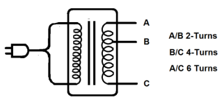
Some of the simple industrial units have three taps, often labeled with voltages. By choosing two of the three provided taps, you can access three different amp-outputs (plus a different voltage as an aside). Various emails to me and videos I've watches indicate that the output fat wires have a low-turn-count coil on the secondary, and a single additional tap that cuts-in at a location about 1/3rd the way down the number of coils. I made this drawing to show what I am certain it looks like. I am very comfortable playing with the low voltage side, and writing about it for others to play with that side, safety-wise.

RSU4.png

xxxxxxxxxxxxxxxxxxxxx

Those videos I mentioned also used a twistable knob to adjust something. I am certain it is a robust and simple way to do something that is useful. How does that knob work in conjunction with the three output taps?

Lew sent a pic of the transformer that he pulled out. Notice there are several similar taps on the primary (120V) side, which connect to the dial. The higher voltage on the primary side can mean using lower amps/watts on that circuit, so...wires can be thinner. Also, since AC has a switching point 60 times a second where the voltage crosses a zero-volts point, the contacts inside switches for AC can be much smaller than a DC contact, plus they can switch on and off easily without fear of the contacts having a large arc, or welding in the closed position...That being said, I don't want to encourage anyone to play around with the 120VAC side. Its dangerous, and should not be modified by amateurs, like me.

This can be seen when attaching or disconnecting a cable from a high-amp starter battery. The voltage is at a very low and safe 12V, but the sparks are big and the current can melt very thick wire.


I very much am hoping to make a well-performing unit that re-purposes a microwave oven transformer (MOT), and also uses the stock 120VAC primary winding. A fat-wire secondary with a single added tap is easy and affordable to do, so...the multi-taps on the primary and added dial may not be "necessary", but...I will continue to research options for this, while I am making a simple caveman MOT/RSU with only the three secondary taps.

Here is a picture of me, just before I throw the switch on the Franken-MOT.

hqdefault.jpg
 
spinningmagnets said:
Timers ridethelightning recommended an adjustable 555-based timer connected to actuate a solid-state relay, both readily available and cheap (both less than $10 each)

I ran across this while browsing EBAY:
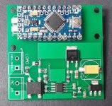
AC / DC converter and Arduino based wireless Solid State relay board
http://www.ebay.com/itm/331634827083 Arudino Relay Board(400).jpg It is intended to be a wireless control for AC lighting however it could easily be repurposed. It would incorporate several components in a single 2 inch square module:
  • mounting location for MPU (Arduino Pro Mini)
    120 VAC x 3 Amp relay
    DC power supply for MPU and Relay
This assumes that the RSU Transformer can be switched on/off via the mains and that the load would be less than 3 Amps. One would also need the appropriate programing cable as the Mini has no onboard USB adapter. Personally I would leave the wireless adapter off however it would allow for several possibilities:
  • Remote low voltage control switch
    Programed control of Duty cycles
    Drive LCD Display
    Several different operation program could be loaded and selected via, toggle switch, pots, etc.
    An additional High Amperage relay to control output side of RSU (use connections intended for Wireless receiver)

With a MPU this can had for about $16-17
 
Dirt cheap caveman current limiter. I finally found something that I stumbled across a while back (so I knew it existed). Earlier, I called an in-line lightbulb a "Light Emitting Resistor" / LER. A bright high-wattage bulb has low-resistance/high current...a dim and low-wattage bulb is high resistance / low-current.

He recommends a large 250W bulb as ideal, to prevent voltage drop. "Shorting" demonstration at 6:44, to show how this will help you.

https://www.youtube.com/watch?v=wRFRwOnLsZI
 
spinningmagnets said:
Dirt cheap caveman current limiter. I finally found something that I stumbled across a while back (so I knew it existed). Earlier, I called an in-line lightbulb a "Light Emitting Resistor" / LER. A bright high-wattage bulb has low-resistance/high current...a dim and low-wattage bulb is high resistance / low-current.

He recommends a large 250W bulb as ideal, to prevent voltage drop. "Shorting" demonstration at 6:44, to show how this will help you.

https://www.youtube.com/watch?v=wRFRwOnLsZI
This is a good concept, but for MOT the bulb must handle 20A, and at 120V it is 2400W bulb :)
 
Ah, I knew there must be something I was missing. Thanks!

What kind of cheap resistor could we put on the input, to limit the output current to 40A? (Or do I have this worng?)
 
spinningmagnets said:
Ah, I knew there must be something I was missing. Thanks!

What kind of cheap resistor could we put on the input, to limit the output current to 40A? (Or do I have this worng?)
What is the purpose of this resistor?
Blower (hair dryer) makes a good, cheap resistor at those power levels, with built in cooling.
 
spinningmagnets said:
Ah, I knew there must be something I was missing. Thanks!

What kind of cheap resistor could we put on the input, to limit the output current to 40A? (Or do I have this worng?)
Didn't you say you had one of these?
prod_5697311327

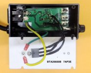
This is what it looks like inside. Router Speed Control 001(Inside-600).JPG
That chip that is screwed onto the back is a hefty Triac (note the part number in the picture).
That dial on the front is a potentiometer that controls the triac (when the switch is in the "Variable" position).
It is going to be hard to beat that for a variable control until you know just how much impedance you have in the finished transformer. Even then it may prove to be the most practical/econimical solution.
Ref:
PDF Data Sheet
http://www.st.com/content/ccc/resou...df/jcr:content/translations/en.CD00002264.pdf
 
Yes, I have two of those, but I don't have a MOT yet. I have been shopping locally, and also working on other projects. If I don't find one the right size soon, I will just buy one off of ebay. Also waiting for a clamping meter to arrive, so I can measure amps...
 
spinningmagnets said:
Yes, I have two of those, but I don't have a MOT yet. ... .
My understanding is those are getting harder to come by as newer Microwaves use a 'cheaper' solution.
spinningmagnets said:
... Also waiting for a clamping meter to arrive, so I can measure amps...
Ditto as well as one of these
https://www.amazon.com/gp/product/B015MTGZ4S
41jlEqF%2BCBL._SX466_.jpg

for which I have an addition use in another project.

As a side note: I do now have some copper strips (thank thee :D )
 
Found another interesting video about a DIY AC power supply. He uses a repurposed MOT that he has rewound to take his 120VAC input and put out AC current from 0 to 240 volts. To control the output voltage/current he uses a 220 volt triac speed control that he got on Banggood to control the 120 Volt input.
https://youtu.be/j7shgaJ_mXk


Sooooooooo ... I went looking on Banggod.
I thought that I found a very good deal but rechecking specs (which on Banggood are subject to question) not so much.

Next choice:
https://www.banggood.com/AC-220V-40...tronic-Motor-Speed-Controller-p-1093435.html?
$6.83 shipped from China
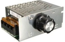
SCR Speed Control.jpg
Input voltage: AC 220V
Voltage regulation: AC 0-220V
Maximum power: 4000 W
Current: 25A

Pros:
Full metal case isolates high voltage
Full range voltage control (the first one was only partial range and had two different ranges listed)
Rated for way more current than needed (i.e it aint gonna burn up)

Cons:
The vendor neglected to specify the dimensions.
 
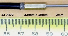
This is my first try shot at a probe.Probe 002.JPG
That is a 12 AWG fine strand copper wire "twisted" into a 2.5mm x 15mm brass stand off with a Saipen 2mm Stainless spoke screwed into the other end.
Note that I can NOT get all the strands into the standoff although the connection does seem firm.
The 2mm spoke screws in a bit loosely but it also seems firm.
My VOM meter can not read any resistance through any of this.

For the record:
Copper electrical resistance: 1.67 to 1.72 ohm.m
316 SST electrical resistance: 74.96 ohm.m (highest resistance of commonly available metals -- except nichrome)
That is a ratio of about 44:1
Brass electrical resistance: 4.66 to 14.37 (depending on the specific alloy)
Reference: http://www.structx.com/Material_Properties_004.html


Lessons Learned:
For 12 AWG one really needs a min 2.0mm hole (2.5 would be better).
The minor dia of M2.5 is 1.8mm. The threads need to be enlarged or a M3 standoff should be used.

For 10 AWG one really needs a min 2.6mm hole (3.0 would be better).
The minor dia of M3 is 2.4mm. The threads need to be enlarged or a M4 standoff should be used.

Some additional form of binding is needed for a proper mechanical and electrical connection around a 2mm SST spoke shaft (set screw?).
This might be a challenging task for a person limited to common hand tools given the minimal size of the standoffs.
While this approach would potentially produce a very compact set of probes a more practical design is needed.

I think I might try drilling out the left end until it is large enough for the cable and then solder it in place.
Will the solder melt when the probe is used to heat a joint .. well I do not know.
Neither do I know any way to find out short of trying it.
 
Well one always needs a plan "B". Sometime one must use plan "B".
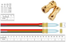
What is really needed is something made of copper or brass, is inexpensive, small, with two different size holes in it and has screws to hold things is place. There does exist a piece of hardware that meets this criteria: brass shaft couplings for RC aircraft.

You can find these on EBAY for as little as $0.99 each. They have a 9mm outside diameter and commonly 20mm long. They also make some 35mm long but those are hard to find and are more expensive. Be aware that the Chinese EBAY vendors tend to have pictures of the longer one but the description reveals that they only sale the shorter version. The do not seem to consider this practice as being 'deceptive'. The couplings are available to fit any combination of the following shaft sizes:
. . 2mm, 2.3mm, 3mm, 3.17mm, 4mm, 5mm
The 2mm (for the spoke) x 3mm (for the wire) seems best suited for this application. The [strike]3.17mm[/strike] 4mm might be a better fit for the #10 AWG cable. The good news is that you can always use a small drill to enlarge the either of the holes. The coupling have four [strike]M2.5[/strike] M3 set screws to hold the shafts (or in the case the wire and SST probes) in place. My problem was they just seemed a bit large. So I did a drawing of the M2.5, M3, and M4 standoffs along with a 2mm x 3mm shaft coupling to get a bit of perspective.

Then I did a drawing of a possible design for the core of a resistance soldering hand unit. The only special work that needs to be done is to file, grind or mill a 1mm thickness off one side of the coupling. Then the couplings are glued to a piece of 1mm x 9mm x 150mm phenolic (i.e. perfboard, pcb board). The board provides insulation between the conductors as well some stiffening for the handle. One might want to use two additional pieces (1mm x 9mm x 130mm) of the board to create a stiffer handle. Then one only needs a couple 50mm long 2mm SST spoke shaft (grind points and bend to suit) and the 10AWG wire. This results in a core that is only 9mm x 17mm at its largest point. In the drawing below the shaft tips are shown with a 2mm separation.
Tips Coupling 2x3 coupling (600).jpg
I am thinking that something like MG Chemicals Thermal Conductive Adhesive 8329TCM could be used to bond the couplings to the phenolic substrate. Then a couple of wraps Kapton tape around the reduced center section to hold it place so it can cure. Then something like Scotchcast could be used to form a handle around it (that is the stuff they make fiberglass casts out of).

The attached PDF is the full scale drawing.
View attachment Tips 2mm x 3mm coupling.pdf

EDIT, 26 Jul 2017:
the 3mm hole size is too small for the fine strand #10 AWG cable

Reference:
http://www.mgchemicals.com/products/adhesives/thermally-conductive-adhesives/medium-cure-thermal-conductive-adhesive-8329tcm
Adhesive: https://www.amazon.com/dp/B00HTV1TXA $10.99
Scotchcast: https://www.amazon.com/gp/product/B00ZVUQXT6 $10.00
 
parabellum said:
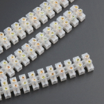
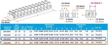
Why not simplify it more :D
Available in every hardware store in any size, shell is made of brass usually
Those would work as well :)Terminal Strip (799).JPG
However I think it might make for a bulkier package. In my case I am rebuilding a very old Hotip RSU.
I am probably a bit too picky about the appearance. :cry:
 
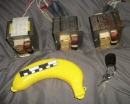
Last week, I didn't even have one MOT, and now look at me! (Thanks to aroundqube for two of them). A local appliance repair shop keeps a pile of old microwave ovens so they can cannibalize them to repair old microwaves, since the designs are upgraded (made cheaper?) every couple of years, and repair parts are getting hard to get. Most people just trash a broken microwave oven, and buy a new one...if the old one lasted 3 years, and a new one is only $100.

The MOTs are often pulled to cut the copper out of them. Also, there is a new generation of microwave ovens that will no longer use these large MOTs. So...grab them if you see one in the trash. Even if they are half this size, it would still work as a 6V / 50A RSU.

MOTthree.jpg
 
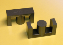
Stacked silicon-steel lamination cores for MOTs has been the standard in the past. However, ferrite cores are more efficient at higher switching frequencies, and their higher efficiencies mean they are the trend for the near future. As a result, salvaged MOTs with ferrite cores will be smaller. This is bad for DIY spot-welders, which thrive on the 400A that results from a 1.5T/2.5T secondary added to a 1500W large MOT. However, for the 40A-70A that we need for RS, this is quite a windfall. The smaller ferrite core transformers may be perfect for this.

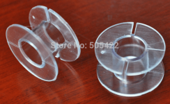
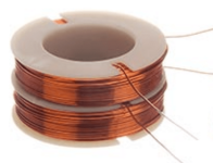
Since the new ferrite cores are cast, the trend has been towards using the ETD style, with a cylindrical center-post (reportedly 10% more efficient?). It is easy for machines to wind the primary and secondary coils onto plastic sleeves, called bobbins/spools (seen below), which easily slide onto the center post. Two identical "E" sections from the ETD style form the core. A quick search of ebay results in the ETD44 as being fairly available, and cheap at $8 for two E-sections (EDT44 = EDT style, 44mm along the E-section's long dimension, with all EDTs having the same proportions) You may find some larger examples (I have seen EDT59), and there are hundreds of selections in the smaller sizes.

http://www.butlerwinding.com/bobbin-wound-transformer-theory/

This is reassuring to me that a DIY RS transformer will remain an option for some time to come. The next generation of salvaged trash-day MOTs will work for RS, and for those who don't want to wait to get lucky-enough to find a free one in the trash, we can affordably purchase new cores to wind our own transformers.

MOT3edt.png

MOTedt2.png

MOT4.png

10-0134-002.jpg


Mass-production and improved manufacturing methods are making these smaller and more efficient ferrite-core MOTs very affordable. As a point of reference, the long dimension of the "E" section of the large "old style" laminated 1580W MOT I have is....98mm (3.8 inches). If the scaled-power is the square root, then...half that dimension is about 1/4 the power so...a 400A old style would be 100A on the new "1/2-size" style EDT44 ferrite-core? Add a fan and we are definitely in business!

Also, I learned it is possible to run two small MOTs with the secondaries in parallel to get higher amps than a single small MOT.
 
How about core saturation at those currents?

Good point, I haven't even finished my list of experiments for the standard MOT I have here, and I was already speculating about a new style I have no experience with.

https://ludens.cl/Electron/Magnet.html

Ferrites are the most versatile materials available for magnetic cores. While they saturate at lower values, typically 0.3T, they exists in a tremendous range of permeabilities: It's not hard to find ferrites with permeabilities as low as 20, or as high as 15000! The inexperienced user cannot tell a ferrite core's magnetic characteristics simply from looking at it. Even if two ferrite cores look exactly alike, one can be 1000 times different from the other! So, make sure you KNOW what material you have, before starting your calculations! [ie, for calculating how to wind the coils to achieve the desired result]

In any case, the most common ferrites fall into two categories: Power ferrites, used for switching power supplies, fly-backs, TV yokes, etc, that have a permeability of around 2000 and low loss at frequencies of about 20 to 100kHz; and RF-type ferrite, with permeabilities of around 100 to 1000, and a loss characteristic that makes them useful at least through 30MHz. But there are many ferrite types that can work at much higher frequencies and have lower permeability. The permeability values above 2000 are reserved to rather special-purpose cores intended for wideband transformers, transducers, or noise absorption.


xxxxxxxxxxxxxxxxxxxxxxxxxxxxxxxxxxxxxxxxxxxxxxxx

As much as I hate buying anything through AliExpress (the Chinese ebay), Its undeniable that so much manufacturing has moved away from the US that some items are only available from China/India/Mexico/Indonesia/etc. Now that I know the proper search terms, I found a fairly large E/E ferrite core with included plastic bobbin/spool for $30. Height and width is about 59mm / 2.3 inches. That doesn't sound huge, but it is rated for 1,000W, and we only need about 400W. Now, I just need to find a pre-wound primary bobbin/coil in this size that produces one-volt per secondary turn. The primary is likely to be a pain, and the secondary should be very easy.

2pcs ETD59 12+12pin 1kw transformer frame bobbin TDG TP4 ferrite core soft magnetic core horizontal

As far as size per dollar, if you don't mind the slightly less efficient square central post, you can get an 85mm / 3.3-inch with a square center core and bobbin for $34 (TangDa EE85B, or...the 65mm version EE65B is $23). If money is no object, there are sizes in this style up to EE240 / 9.4-inch
 
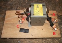
Progress is slow, but I want to finish this. It's my understanding that the secondary coil must be wound in the same direction as the primary (makes sense). If you are starting at post "A", and wind in the direction of the black arrow on the side (counter clock-wise, CCW), I would end up with 6 turns that end at post "B".

I am inserting a "center tap" at the 2T mark, so there are two turns with red insulation, then four turns with black insulation (those were the colors that were handy, in a size that was large enough to fit)

A-C = 2T
B-C = 4T
A-B = 6T

I will also be winding one of the other MOTs with 2T of the fattest welding cable I can fit, since the possibility exists that the "router speed controller" can dial down the amps. If that works as I believe it will, then we should start with the highest possible amps and adjust it down to the level that works for the job at hand.

Although this first MOT build (shown in the pic below) has a 2T winding on it, the amount of copper mass passing through the magnetic flux-field on that 2T winding is only 1/4 of what is physically possible, so I anticipate that the "fat cable" 2T that will be using an identical core will provide 4 times the amps.

I plan for the lugs on the leads to be pressed directly against the lugs coming from the MOT, so the bolts that form the three lugs will not be conductors, although they will be "live" with volts/amps. I drilled a 5/16 hole in the pallet-wood and inserted the bolts from underneath and locked-in each of them with a nut. Then added wood cross-pieces underneath so the bolt heads are not touching the table. If this MOT works well enough to keep its current configuration, I will spread insulating goop on the bolt-heads (underneath).

The square "windows" on the transformer-core have sharp edges, so I glued thick wooden "paint stirring sticks" under the place where the end-turns are, after filing and sanding their wooden edges off (half-moon cross-section). This way the coils are tight and oval, rather than square, with sharp edges. Wood or plastic would be acceptable for the rounded end forms, due to eddy currents causing heating (no aluminum or brass).

MOT19.jpg
 
Looks like my MOT battery tab welder, but my logic board is from a guy in the UK
he's on this forum too I think
http://avdweb.nl/tech-tips/spot-welder.html

My MOT's were from the recycle bin behind Value Village.
Next project using them will be an Arc Stick Welder.
 
That is a very well-done tutorial! Thank you for posting that. There are several clever features that I had not seen in the many youtube spot-welders I had found. It looks like you are using three turns of the fattest wire that could fit. Did you try 2T or 4T before you settled on 3T?
 
Back
Top