DIY spot-welder, transformers from microwave ovens?

IanFiTheDwarf said:
for the timing I have ordered this http://www.ebay.co.uk/itm/322032196773?_trksid=p2057872.m2749.l2649&ssPageName=STRK:MEBIDX:IT , it can produce a pulce down to 0.1s which im hopeing will be ok

100ms is too long I think, if fechter is using 15ms successfully you may end blowing holes in your cells or over heating them. A simple arduino sketch will at least give you 10 ms resolution as I'm pretty sure UK mains is 50 Hz. Off topic , how did you get on with your axial flux motor?
 
There were quite a few similar timers om ebay but only a couple went down to 0.1s, most had 1 second as the shortest time setting. The one I ordered is coming from china so could probably be sent anywhere.

I will remove the relay from the board and connect to a ssr. I have a few 10A ssr's lying around which are rated at 60A for 0.1s and almost 30A for 10 seconds which is more than a 16a or 20a breaker would take anyway so should do fine.

I would like to have a go at a microcontroller timer so I could do double pulse but its been years since I did anything with micros so this timer should get me up and running a lot quicker.


I have been thinking about welding copper and from what I can see one of the bigert problems is the tip material. Coper tips conduct well and dont need very high voltage but will weld to the copper strips, carbon wont weld to anything but will need much higher voltage to overcome the high resistance, tungsten I am not sure what the resistance is but I would expect a thin layer of tungsten over copper might work well. How about filling a tungsten tube like a piece of a cooker hob ring with copper?

might be worth a try.
 
I have reserched and there are people getting good results with 50 to 300ms, some with a resistor to reduce power which I will have on mine. The timer I picked is a quick fix off the shelf solution. Ptobably not the best but im hopeing it does the job

I havent got back to my axial motor yet but hopeing to when I have finished building my workshop. I need to get my lathe set up and get a mill or router to make some parts
 
I'm thinking of using copper rods that are drilled out in the middle and pressing in tungsten rods. Sort of like a wooden pencil. The electrical path length through the tungsten will be short, just at the tip. The copper will also help cool the tungsten. Otherwise some kind of copper or aluminum clamping fixture that clamps the tungsten rods so just a short length is in the path. This would allow easy electrode maintenance.

I really have no idea how much sticking will happen until it is tried. Higher currents with shorter times seem to be successful.
 
I might have some old tig welding electrodes lying around which are down to the last few cm. I'll see if I can drill a piece of copper and hammer one in so only a couple of mm is left sticking out.
 
i build spot welder by microwave oven transformer with arduino timer cost budgets 50

Equipment needed

1. microwave oven transformer (800watt) 20 $
2. Arduino Uno R3 10 $
3. wire copper (25SQM)1.5 M 5 $
4. charger 5V (Charger mobile) 5 $
5. Solid state relay 40 Amp 10 $

: [youtube]UK3ahgJyOjE[/youtube]
 
peleap said:
i build spot welder by microwave oven transformer with arduino timer cost budgets 50

Equipment needed

1. microwave oven transformer (800watt) 20 $
2. Arduino Uno R3 10 $
3. wire (25SQM)1.5 M 5 $
4. adepter 5V (Adepter mobile) 5 $
5. Solid state relay 40 Amp 10 $

: [youtube]UK3ahgJyOjE[/youtube]
Thats great. Could you please share more details. How the components are wired and the program for arduino.

Sent from my MI 5 using Tapatalk
 
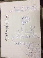
wiring diagram spot welder
IMG_0449.JPG
IMG_0447.JPG
View attachment 1

solid state reley
http://www.ebay.com/itm/SSR-40DA-3-32V-24-80V-40A-Solid-State-Relay-Module-for-Arduino-Fast-Switching-/381141366167

arduino
http://www.ebay.com/itm/New-UNO-R3-Development-Board-ATmega328P-for-Arduino-Compatible-with-USB-Cable-/281638689314?hash=item4192f95a22:g:Dx0AAOSwm8VUwv1m

charger 5V
http://www.ebay.com/itm/EU-Plug-5V-2-5A-Micro-USB-Charger-Power-Supply-Adapter-for-Raspberry-Pi-3-Tablet-/152199717485?hash=item236fcf626d:g:E2EAAOSwgZ1Xqgz3


arduino code >>
 
Thank you Peleap.. That does help a lot..

But not all of us have that technical know how. It would be great if you could do a Instructable and even feature it on the website.

There are not many diy spot welders that every one can make.
Thanks once again

Sent from my MI 5 using Tapatalk
 
The idea sounds good but I can only destroy eight batteries before I have to buy more.
The Chinese stuff seems to be hit or miss. The usual quality fade.
The Double pulse triac controller is around 50.00 U.S. Lately I have not had good luck sending money overseas.

I think I will just lurk here for a while
 
I went in behind a thrift store where they had a garbage bin full of microwaves. I snagged the biggest ones I could. Find the highest wattage and take them. Be sure to drain the capacitor energy when disassembling. I used this guys design had to solder up the board myself, he supplies everything else except the pcb components. I will try the adruino welder next if I dont have to do any programming. My welds on my used a123 26650 M1B's were good. His design allows you to adjust the pulse timing. I think I left the MOT shunts in, but will try taking them out. I tried two windings, the lower the better I think.
I bought welding cable from Princess Auto (Harbor Freight) 4awg or 3awg worked for my 1800W MOT. 2 wraps.
 
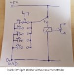
Here is a youtube of a guy who put together a MOT welder, the interesting part is the timer. He uses a simple dial to select any one of several capacitors. He used five selections, but you could easily chose values that are smaller steps, and also have more capacitor choices than five. If the range of capacitors was too low or too high, this design can easily change them, and also replace one if a cap dies.

As I stated earlier in this thread, I don't think the MOT-style welder is as precise and adjustable as I would like (for welding the bus strips onto the cells), but I do like the idea for welding series strips onto the parallel strips, which would be much more forgiving. Also, I am a fan of using fairly thick copper ribbon for the series connections, and copper needs much more energy to weld. Most commercial spot-welders don't go as high as I would need, since their adjustment range is made for the common 0.15mm-0.25mm nickel flat ribbon.

https://youtu.be/KU1e-zq9hrw?t=82

MOTtimer.png

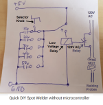
Above is the drawing he posted in the video, and below is what I think is happening. I would appreciate any help anyone could give me to figure out how this works, and what components would be needed. (also possible failure modes?)

MOTtimer.png
 
Pretty crude, but I guess it would work. I'd use a solid state relay. You'd have to experiment around to see what value of capacitor gives what time.

You charge up the capacitors with the small power supply, then discharge into the relay coil. This will make it close, but only briefly as the caps will discharge quickly.

It may also work to use a single cap, but vary how much voltage it gets charged up to in order to control the time.
 
There are some much slicker designs. The arduino are far more interesting and work better, IME. I did recently see a micrwave build that incoporated and arduino board controll that had decent reviews. Google will find it..
 
fechter said:
Pretty crude, but I guess it would work. I'd use a solid state relay. You'd have to experiment around to see what value of capacitor gives what time.

You charge up the capacitors with the small power supply, then discharge into the relay coil. This will make it close, but only briefly as the caps will discharge quickly.

It may also work to use a single cap, but vary how much voltage it gets charged up to in order to control the time.

If you have a moment, thoughts on this one?
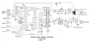
http://www.avdweb.nl/arduino/hardware-interfacing/spot-welder-controller.html
 

Attachments

  • IMG_1326.JPG
    IMG_1326.JPG
    40.2 KB · Views: 3,986
tomjasz said:
If you have a moment, thoughts on this one?
http://www.avdweb.nl/arduino/hardware-interfacing/spot-welder-controller.html
I recently built that one. First as 5.2(?) version firmware, without display, later upgraded firmware to 6.0 and added the display.
After upgrade, I experienced quite a lot of anomalous behavior, where the controller seemed to work but in actuality did not weld. I think the welding pulse was either timed off or too short. Fixed it by adding large electrolytic cap. , parallel to C8 (after rectifier bridge, before 7805 regulator) to controllers power supply circuit. I guess the welding pulse made a quite a voltage sag in my mains line coming to welder, so the small transformer feeding the controller and added display was not able to keep up with demand, causing brownouts.
Anyway, since the fix, it has been working flawlessy. Just recently completed a build where I used 12x0,15 nickel tabs I had to be very careful not to vaporize the tabs. Filing the ends to proper shape on electrodes was crucial. I think the timings were (from memory, may be wrong here) 50ms preweld, 200ms pause and 150ms welding pulse. Anything above that resulted in flash/sparks and me cursing like a sailor.
 
I actually kinda like that design with the capacitor selector. Very resourceful use of low tech parts.

A friend of mine once showed me a spot welder they'd developed at DND (about a hundred years ago) that used a rotary phone to *ahem* dial in the number of pulses needed to make the weld.

Life before arduino. Those must have been dark days...
 
hello everybody, i'm new here and need some help.
i may build an e-bike some day, i'm still only collecting info for now but one big part of it will be to build a 18650 battery pack.
to do this i built a diy spot welder from scavenged parts including a microwave transformer.

but it is working "too well" or not so well in fact : i tend to pierce through the battery shells and nickel strips.
only testing on dead cells but i can't use it untill this problem is fixed :(
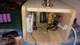
below are some photos of the welder. the problem with scavenged parts i used is i don't really know their caracteristics : the power of the microwave oven or the transformer (except it is 220v 50hz because france), or the gauge of the copper cable i used, .....
i used a timer relay from ebay thinking it would limit the damage but even with it on minimum time, i get sparks and holes.
what did i do wrong ? should i add or remove a turn on the winding and why ?
other ideas? i 'd like to keep it as simple as possible since i lack knowledge in electronics/electricity in general,
any help is welcome. thank you.
pictures :


Sounds like your pulse length is too long. Don't reduce the amps.... Shorten your pulse. Hot and short is the way you weld with minimal heat permeating the surroundings.
What sort-of timer are you using. How does it work and what pulse lengths can you achieve?
 
you can see the timer i'm usig on pic 2 an 3, a cheap timer relay from ebay as i said. i think it is this model : https://www.ebay.fr/itm/5V-30V-Delay-Relay-Timer-Module-Trigger-Delay-Switch-Micro-USB-1343Z/183863247036?hash=item2acf1a80bc:g:qY4AAOSw8ZhdFmM9

the pulse seems very short (way shorter than in some youtube videos i saw) but may be not enough ? i thought it is not precise enough to make extra fast cuts, resulting in too much amps punching holes. so i was thinking first about reducing the amps by removing (or adding ?) turns on my winding but here is my problem :

you can find many DIY MOT welder tutorials saying "take x AWG and make 2 turns!" or take y AWG and make 4 turns! " but i found none to explain clearly the relation between the number of turns and the desired amp output. and again, i don't even know the awg of the scavenged cable i'm using.
-> So, in my case, keeping the same transformer, the same timer and the same big copper cable, if i want something "less powerful", say less prone to sparks and holes, should i remove or add turns and how many ?
 
Back
Top