Does this imaginary voltmeter that I want exist?

harrisonpatm

10 kW
Joined
Aug 8, 2022
Messages
829
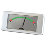
For the current project, I want to see if I can setup an analog voltmeter next to my speedometer. Not as accurate as a digital display, but an analog needle will instantly show sag and rebound better than digital. But biggest reason is aesthetics: the speedometer is a needle, I want a voltmeter next to it to also have a needle.

I'm wondering though, for my 28s Li-Ion battery, is there some manufacturer out there that sells an analog meter displaying only in the range of 80-120vdc? That'd be pretty cool if it did. I have found meters that read from 0-120v, or like 0-150v, but then the first two thirds of the range would be wasted.

This product probably doesn't exist, but I just thought I'd check in case someone has heard of those before.
 
I've thought about this a bit before, some things I thought of.
- vibration could be a big problem for an analog meter, likely you would be better off with a stepper motor and a needle like car speedometers use, they are cheap and easily available, but of course add big time complexity because you need a microcontroller and some code to control it.
- I doubt there is a meter with a non zero starting point but it should be possible to create a circuit that could offset the pack voltage so whatever the lowest voltage is shows as zero and the max pack voltage shows as the top of the meter. Not an electrical engineer so I don't know the exact circuit but basically you'd need to generate a reference voltage at either the fully charged voltage or the fully discharged voltage somehow and then measure everything relative to that. You could also scale it down from the high voltages of the pack at that point. Again though, complexity.
- You're kind of the opposite of most people. You want to exaggerate sag whereas most people who don't know what it is panic and assume something is wrong when voltage/estimated battery capacity suddenly drops so engineers try to come up with all kinds of sag compensating algorithms. Not at all a helpful insight, but I find it quite amusing anyway :D
 
vibration could be a big problem for an analog meter
This I disagree with. If vibration were a problem for analog meters, then we wouldn't have analog speedometers. There's lots of different ways to smooth out a needle movement, like springs or small flywheels. But for more direct experience, I have used an analog ammeter on my current motorcycle for 2 years. I can attest that while vibration isn't an issue, what is an issue is angle: my dial meter is at about a 30 degree angle, so gravity keeps pulling the needle a bit further down than actual amps. Which is okay, the benefit to having a dial gauge is seeing the needle jump when you twist the throttle. I just realized after awhile that while it's nice to see amp usage, it'd be nicer to see live voltage, sags and everything.

I may even transfer the ammeter over to my next build, and if I do I'll mount it more closely to horizontal. It'd be cool if I were able to also find an appropriate dial voltmeter. And have three dial gauges next to each other: speed, volts, amps.
- I doubt there is a meter with a non zero starting point but it should be possible to create a circuit that could offset the pack voltage so whatever the lowest voltage is shows as zero and the max pack voltage shows as the top of the meter. Not an electrical engineer so I don't know the exact circuit but basically you'd need to generate a reference voltage at either the fully charged voltage or the fully discharged voltage somehow and then measure everything relative to that. You could also scale it down from the high voltages of the pack at that point. Again though, complexity.
I do like your suggestions, but if I were to design this gauge, mechanically, I would just have a manual way to keep the needle from returning to zero. A spring is attempting to return the dial to zero, and if someone were to simply install a rod, pin, ect, at a desired point, the needle would just come to rest a different point. Much less complex.

And I especially like your suggestions because:
you would be better off with a stepper motor and a needle like car speedometers use, they are cheap and easily available, but of course add big time complexity because you need a microcontroller and some code to control it.
This is a really good idea. I have no idea how to go about doing that (i don't have any programming skills), and I personally dislike the idea of creating a complex circuitry for purely aesthetic reasons. But it's still a really good idea. Maybe I can make friends with someone who could make that for me.

You're kind of the opposite of most people. You want to exaggerate sag whereas most people who don't know what it is panic and assume something is wrong when voltage/estimated battery capacity suddenly drops so engineers try to come up with all kinds of sag compensating algorithms.
Not exaggerate, just measure it. I've been through 4 different voltage displays on my current motorcycle and I've liked none of them for various reasons, but mostly because digital displays have various refresh rates. Analog gauges are less accurate, but the "refresh rate" is infinite, lol. Since I'm familiar with my battery (I'll have made it), I know that sag happens and I just want to be able to see it. I don't even use voltage for range. Typically when I recharge my motorcycle, I reset the odometer to 0. I know my estimated range, and when I see the odometer start to get close, time to charge.

Thank you, this same model is what I used for an ammeter, but for voltage, the dial would never use 75% of that range (0-80v, 120-150v). Lots of dead space for my use case.
 
Alright, now I'm down the rabbit hole, thanks @Epithemeus


I wouldn't know where to start on this, I have no idea how to program, but now I wanna learn just to make a dial voltage indicator. I just need it to read voltage instead of temperature, speed, ect.
 
…. an analog needle will instantly show sag and rebound better than digital.
Well technically that is not true.
the needle is just reacting to a electrical signal, and as a mechanical device it cannot be faster than that input signal,…
….but a digital display can effectively be as fast as the signal.
However,..what you probably mean is you find a needle display easier and quicker to interpret, which is common.(IE: digital clock, vs, analog clock dial )
BUT, as with the clock on your phone , you could simply use a analog needle visual presentation on a digital screen , as some modern autos do, typically with tachometers (fast response)
 
Last edited:
….but a digital display can effectively be as fast as the signal.
Can be, but I guess what I mean is some of the digital voltage displays I've used are only refreshing 2-8x per second.
However,..what you probably mean is you find a needle display easier and quicker to interpret, which is common.(IE: digital clock, vs, analog clock dial )
Definitely agree with that, personally
BUT, as with the clock on your phone , you could simply use a analog needle visual presentation on a digital screen , as some modern autos do, typically with tachometers (fast response)
I could, but now it's getting into aesthetics: I don't want a screen displaying a needle, I want an actual needle, lol
 
This I disagree with. If vibration were a problem for analog meters, then we wouldn't have analog speedometers. There's lots of different ways to smooth out a needle movement, like springs or small flywheels. But for more direct experience, I have used an analog ammeter on my current motorcycle for 2 years.
Well analog speedometers are made with stepper motors and definitely wouldn't have any issues with vibration. I just kind of assumed that a spring based voltmeter would have issues but ultimately my theoretical musings is trumped by your personal experience with your ammeter.
Alright, now I'm down the rabbit hole, thanks @Epithemeus


I wouldn't know where to start on this, I have no idea how to program, but now I wanna learn just to make a dial voltage indicator. I just need it to read voltage instead of temperature, speed, ect.
That's the exact stepper motor I was considering when I was considering making myself a custom display (I too dig the analog aesthetic)

It's definitely a deep rabbit hole should you choose to delve (and if so I wish you a good journey and hope you learn lots) When I was considering making a custom display with analog gauges I ultimately gave up on it because I couldn't think of a good way to make a waterproof enclosure, too outside my skillset. Also scope creep, I kept thinking of more and more things I wanted it to do :p
 
Well I ended up in a rabbit hole of my own. You need sniped me!

I found this, it's basically what you want to do but with a lower battery voltage so the answers should hopefully be applicable. Of course parsing through the pretty technical answers is a challenge. Is it simpler than learning to code though? :p
 
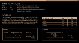
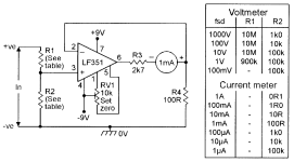
Analog meters use a coil to move the base of the needle. The coil is driven by current, so you can use "any" analog meter to display any data you want.

You only have to create some "simple" op-amp electronics that convert the voltage range you want to read into a small enough current to drive the meter you are using over the mechanical range the display has.

This page, down in the analog section, has various circuits to do this sort of thing
like this, though in your case you'd probably want a scaling op-amp so the full scale of the meter only reads the empty-to-full votlage range of the pack.
1712801613039.png

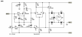
This page goes even more basic and uses transistors
1712801445442.png
 
I could, but now it's getting into aesthetics: I don't want a screen displaying a needle, I want an actual needle, lol
????..your preference i guess,….but it seems like you will just be making your life hard for an inferior result !
An electronic device could present the info in so many different ways, as well as storing the data for later analysis.
 
This was an interesting read:
Basically what @amberwolf suggested. Find a couple cheap voltmeters, open them up, then change the resistor and diode values until you get the range you want
 
I got 2 of these, $1.89 each, and I got the 0-50v ones, which shouldn't matter for my purposes. Since all the options start at 0V, the expectation is that when I open them up, I'll find a resistor in series with the coil, but no diode. Based on the above linked example from stackexchange.com, I would expect that in addition to changing resistance values, I will probably need to add a single diode so that no current goes through the coil until the voltage is above the diode's value. So I'll probably order these, or similar, 68v 5w diodes. Battery will be 28s and the cells are rated to discharge down to 2.5v safely. I won't want to pull them down that far on a regular basis, but all the more reason to have a meter to let me know if they're sagging down that far, then I'll know to charge the battery or stop throttling so hard. So 2.5v x 28s battery = 70v, meaning that I'll want the adjusted range to be 68v to know when the pack is hitting its lowest voltage.

After I get them I'll do some bench tests with different resistance values and report how well it goes.
 
Current thru the meter should be *extremely* small, so diodes (and resistors) don't have to be very big. Most I've ever opened up use ones the size of the tiny glass 1n4148 if they're discrete parts (some use smaller SMT parts on a board).

If the meter takes a lot more current then it needs bigger diodes....but I doubt those do.
 
Really surprisingly easily!

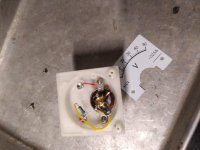
The two meters I ordered arrived. I should have paid more attention to the listing, they were much smaller than I thought they would be, only a 40mm square display. That's okay, they were dirt cheap and I wanted to just check and see how easy the process was.

I went back to the stackexchange page linked above, where a user helped someone with a formula for changing a voltmeter's deflection (scale) and start voltage. Deflection is determined by total resistance of the circuit. As I expected, since I got a voltmeter with a start voltage of 0V, all I expected to find in the meter would be a coil and a resistor. I wasn't disappointed.
IMG_20240420_125255.jpg

Start voltage is easy, just a diode, I got a 68v diode because 2.5v x 28s = 70v. Then my max voltage would be 4.15v x 28s = 116.2v. Theoretically I would also want to know 4.2v x 28s = 117.6v. My desired deflection is then 117.6v-68v, or 49.6v.

Coincidentally, luckily, I randomly selected cheap Aliexpress voltmeters with a range of 50v. Meaning, same deflection. Meaning, I wouldn't need to calculate a new desired deflection, and then order or find resistors to achieve it. I wish I could say I planned it that way, but I didn't.

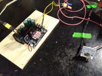
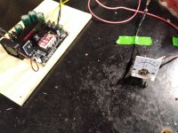
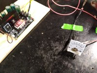
So, all I needed to do was to test the meter with a diode in series. I got a boost converter that I'm planning to use as my charger, and yeah, that's it, it worked. Forgive the low quality pictures, but I just adjusted the output voltage from 66-128vdc, and was able to see the needle move and correspond to the correct scale.
IMG_20240420_144842.jpgIMG_20240420_144754.jpgIMG_20240420_144715.jpg

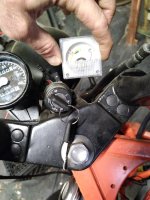
All that's needed is to draw up a piece of paper with a new scale to insert behind the needle instead of 1-50v. And even though the small meter I have would kinda sorta work where I want to mount it on the motorcycle:
IMG_20240420_145708.jpg

I'm gonna go ahead and try to find one with a larger, easier-to-read display. I'll still go ahead and modify/mount this one, since I have it and won't take much work at all, and it can be a placeholder until I find a larger meter.

Tl;dr If you want to modify the voltage range of an analog voltmeter, find one that already has the same desired scale that you want, and add a diode. Easy!

Current thru the meter should be *extremely* small, so diodes (and resistors) don't have to be very big. Most I've ever opened up use ones the size of the tiny glass 1n4148 if they're discrete parts (some use smaller SMT parts on a board).

If the meter takes a lot more current then it needs bigger diodes....but I doubt those do.
You're of course totally right, the 5w ones I got looked small on their own, but they're huge compared to what's in this meter. I'm gonna use them anyway, since I have them, and maybe if/when I find a larger meter the diodes I have to use won't be as oversized in comparison.
 
Thanks for digging up and testing the simple meter mods; this makes it much more likely that I will (eventually) make my own version (the simple but still much more complex op-amp scalers/etc have kept me deterred from doing one for a long long time).
 
Thanks for digging up and testing the simple meter mods; this makes it much more likely that I will (eventually) make my own version (the simple but still much more complex op-amp scalers/etc have kept me deterred from doing one for a long long time).
Thanks to the forum for pointing me towards such an easy mod. I still want to learn how to program a stepper, because as mentioned above, a coil-driven needle still bounces and droops. But for now this is going to be exactly what I was looking for.
 
Pages like this may help learning about steppers,
but RC servo motors would be more precise without adding external gearing, if that matters. (since the servos are fully variable)

Steppers have a certain amount of degree movement per step, usually 1.8 for the typical one. For stepper gauges, it depends on the design, but various places I've read about them back when I was looking into them for stuff*** I found about half a degree per step as an average number for dashboard ones. Might be better more recent info.


RC Servos are controlled by a PWM signal continuously sent to them. The pulse width that's sent to them varies the angle they are driven to by their internal control driver chip, so say you have a 180-degree servo, and you send a 50% duty cycle PWM signal, they go to say, 90 degrees. Lower the DC % and the motor moves to a different position, etc.

They dont' require "finding home" with an external home sensor like a stepper does (a stepper has no way to know "where" it is, by itself), since their internal design has a position pot that feeds back into it's own control chip; all you have to tell it is where you want it and it moves there.

A stepper system requires a home sensor (like the end stop switches on 3D printers' x y z rails) for the controlling MCU to read and it requires driving the motor until it reads the sensor has closed (or opened), stop the motor, then drive it / count steps until it is where it is supposed to start at.

So (to me) servos are easier to control than steppers, and they have a lot of gears between the motor and the output, so they might hold a needle of a display in place without any power once driven there, if teh input PWM is turned off. A stepper usually has pretty stiff "cogging" so they may hold a position without power, but if it's a really tiny stepper it may still ahve to have power to hold it there. The tiny servo may take less power.


There are some existing articles out there on using both servos and steppers as analog meters, but the ones a few seconds of googling finds on steppers are so incomplete they're not useful so I didn't link any. The ones on servos are better, but you can probably find good stepper articles.
This one is more relevant to your application but not sure it's complete (didn't read it, just skimmed)


***I sometimes see "complete" car dashboard gauge sets at goodwill, and have occasionally considered using one of them (or parts of) as a dash for the trike. But it's not really the look I'm after; I would prefer the "old aircraft cockpit" look, or old electrical test equipment. .
 
Really surprisingly easily!

The two meters I ordered arrived. I should have paid more attention to the listing, they were much smaller than I thought they would be, only a 40mm square display. That's okay, they were dirt cheap and I wanted to just check and see how easy the process was.

I went back to the stackexchange page linked above, where a user helped someone with a formula for changing a voltmeter's deflection (scale) and start voltage. Deflection is determined by total resistance of the circuit. As I expected, since I got a voltmeter with a start voltage of 0V, all I expected to find in the meter would be a coil and a resistor. I wasn't disappointed.
View attachment 351442

Start voltage is easy, just a diode, I got a 68v diode because 2.5v x 28s = 70v. Then my max voltage would be 4.15v x 28s = 116.2v. Theoretically I would also want to know 4.2v x 28s = 117.6v. My desired deflection is then 117.6v-68v, or 49.6v.

Coincidentally, luckily, I randomly selected cheap Aliexpress voltmeters with a range of 50v. Meaning, same deflection. Meaning, I wouldn't need to calculate a new desired deflection, and then order or find resistors to achieve it. I wish I could say I planned it that way, but I didn't.

So, all I needed to do was to test the meter with a diode in series. I got a boost converter that I'm planning to use as my charger, and yeah, that's it, it worked. Forgive the low quality pictures, but I just adjusted the output voltage from 66-128vdc, and was able to see the needle move and correspond to the correct scale.
View attachment 351445View attachment 351444View attachment 351443

All that's needed is to draw up a piece of paper with a new scale to insert behind the needle instead of 1-50v. And even though the small meter I have would kinda sorta work where I want to mount it on the motorcycle:
View attachment 351446

I'm gonna go ahead and try to find one with a larger, easier-to-read display. I'll still go ahead and modify/mount this one, since I have it and won't take much work at all, and it can be a placeholder until I find a larger meter.

Tl;dr If you want to modify the voltage range of an analog voltmeter, find one that already has the same desired scale that you want, and add a diode. Easy!


You're of course totally right, the 5w ones I got looked small on their own, but they're huge compared to what's in this meter. I'm gonna use them anyway, since I have them, and maybe if/when I find a larger meter the diodes I have to use won't be as oversized in comparison.
Nicely done!
Hopefully you can find a round one that would better fit your bike's style, or cut it to shape and make an enclosure.

I also prefer having a needle for current/voltage on the dash, because the refresh rate of most screens is set a bit too low. It's harder to see peaks.
The only little issues with needle based meters is that they have some inertia, also they aren't easily readable while riding. But they do look cool and it does feel a bit better, like you can "see" or "feel" the power in the system.
 
Last edited:
Nicely done!
Hopefully you can find a round one that would better fit your bike's style, or cut it to shape and make an enclosure.

I also prefer having a needle for current/voltage on the dash, because the refresh rate of most screens is set a bit too low. It's harder to see peaks.
The only little issues with needle based meters is that they have some inertia, also they aren't easily readable while riding. But they do look cool and it does feel a bit better, like you can "see" or "feel" the power in the system.
Someone agrees with me about refresh rate!

I don't need voltage information accurate to decimal places while riding. I just need a general idea of sag and rebound.
 
Back
Top