drive idea....requires brains trust help

rodgah

10 kW
Joined
Dec 23, 2009
Messages
553
Location
Sunshine Coast, Australia
hi guys,

I have a 80100 and a neugart 20:1 box still doing nothing as Im not completely happy with the bike they were destined for. I have toyed with a lot of ideas as some of you know but have failed to do anything yet. Anyway I think I have an idea of what I want but I need some input into the best path to take.

Basically the drive will become a bolt on affair (like the gng drive, or as a cut bottom tube weld in mount brackets and becoming a stressed member of the frame) thru the cranks. I really want the drive to be enclosed for 1 durability, 2 to allow burties optical sensor and 3 noise. Because of the width of the gbox and motor a offset crank sprocket arrangement will be required (like the gng) plus the support bearing will help the FW anyway.

ok so the enclosure is 2x3mm thick aluminium outer plates, one bolts to the output side of the gearbox and the normal mounting surface of the 80-100(but the shaft is cut short and doesnt continue thru the plate). The other plate contains 2 bearings to suit the shaft of the 80-100 and the input shaft of the gbox(as it requires a support bearing to keep shaft alignment). Between the plates is a series of lasercut thick (20mm) sheets of polycarbonate or MDF to create the walls of the enclosure (and not suffer from eddy currents) all held together with a bunch of long bolts around the perimeter. This makes it basically air tight (if I glue the PC or MDF pieces together and add gaskets on either side).

I could then theoretically put a small amount of oil in there. Or I could adapt the sides to include a beast of a fan that sucks air into the motor(thru a filter of course) and exhausts out the other side plate.....blowing into the motor is not an option as it messes with the chain line to the cranks. There will be a 15mm wide 5mm pitch belt between motor and box at 1:1 which I dont think will enjoy oil too much. Running on 18s leaves me with a output of 487rpm (super human I know, but I dont care) and if its a 1:1 transaction to the rear wheel that is 61km/h top speed (perfect for my application).

So my questions are ....

1) oil or air cooling?
2) if oil then will a belt care?
3) how is a 80-100 going to like spinning at 9750rpm?
4) in this config can I remove the skirt bearing?
5) best place for a temp probe?
6) something I have forgotten?

cheers guys
 
full-throttle said:
I've got the same 'problem', well except mine is a 12:1 PLE80. So whatever you end up doing make it two 8)

that shouldnt be a problem FT, you could easily use a 2:1 reduction at the input of the gearbox to get a output closer to pedal candence. I am leaning more toward the fan forced (sucked) idea with the original mount face plate and skirt bearing of the 80-100 removed to improve air flow. The spacers I am tossing between clear polycarbonate or acrylic(though that would ruin the chance of running burties optical sensors but look sooo cool), or cut them very thin ~3mm thick walls in MDF and then cover in a layer of carbon fiber and epoxy.

I have also been thinking that I could run all belts to the rear wheel, obviously that would be a single speed affair, and would require spring tensioners to deal with the run out of freewheels and fw cranks. 8)
 
Subbed. Ive got a ple80 5:1 thats just been put into use with my first crudely made bracket, noisy as hell so anyone developing ideas on noise reduction is gonna get my ful attention.

That and your builds are sick, wouldnt want to miss the show!
 
Here's another one viewtopic.php?f=6&t=34805#p542557
None of them are fully enclosed though.

rodgah said:
you could easily use a 2:1 reduction at the input of the gearbox to get a output closer to pedal candence.
That's exactly what I was thinking of. The input shaft of the GB is hollow, do you think is a bad idea of clamping the pulley to the outside of it? A rod would have to be fitted to the inside of the hollow shaft so the wall doesn't crush of course. And an extra support bearing fitted to the rod.
rodgah said:
The spacers I am tossing between clear polycarbonate or acrylic
PC is much tougher. What about wrapping 2mm sheet around the whole assembly? The round sections can be hot-formed.
 
°Subscribed

KiM
 
this may describe what im talking about a little better.

asdf.jpg


spacer plate is used in layers of ie 20mm thick to build up the walls of the enclosure....in plastic or MDF.

plate 1 is 3mm aluminum (not yet displaying mounting points), HXT and neugart output bolt to this, large cooling holes for inlet into motor.

plate 2 is 3mm aluminum (not yet displaying mounting points), captive bearings holes for both shafts, and fan in the center, externally mounted to suck out of the enclosure.

IMG_0761.jpg


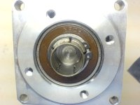
remove the gold piece and skirt bearing to increase flow of air. cut shaft on that side really short, and will require a spacer or hole in plate 1 to not foul on shaft.


have watched burties build from the beginning (reason I bought a neugart in the first place). the other one I havent seen before cheers.

full-throttle said:
That's exactly what I was thinking of. The input shaft of the GB is hollow, do you think is a bad idea of clamping the pulley to the outside of it? A rod would have to be fitted to the inside of the hollow shaft so the wall doesn't crush of course. And an extra support bearing fitted to the rod.

my box as you can see has that big ugly square silver coloured mount on it that as far as i can tell isnt removeable, so that isnt an option for me. My input shaft is hollow, but it is a clamp design like ...

2061.jpg


is yours the same?

I will try to model in 3d and get some numbers on width etc.....i can see it being very wide already, I wanted to have the hxt down the bottom close to the BB and the output up the top, but this is bad for 2 reasons, it requires the 2 crank chainwheels to be close together and that means offsetting the weight to the non drive side of the bike, and 2 there is very little room for a support bearing for the cranks if you use the SBP BB spindle thats only wide on one side.
 
ok I been teaching myself inventor....cool program for anyone interested. First real go at modeling anything in 3d :lol:

so I measured the gap I would have to provide to get out of the magnetic field.....at 32mm it started to pull the pin in, so I made the gap 35mm
3CB6E360-0DE4-4525-B70C-CBD9FC98E689-282-0000007CAF8A01D5.jpg


without endcap....though even with the skirt removed there isnt a whole lot of area for air to pass, through the stator teeth
5D427964-D08A-4E90-BE3F-B51668434DE5-282-0000007CB69BDD61-1.jpg


output side
drive3_zps49058072.jpg


input side
drive1_zps1b98213b.jpg


belt drive
drive2_zps264da8db.jpg


cheers
 
full-throttle said:
Slightly different.

humm, well I dunno how to approach that one...

had a bit more of a play.....getting the hang of inventor a bit now, still cant get my bolted connections to work, but the design accelerator says the belt is good to go at 16mm wide t5 holding 10kw at 9500rpm IIRC.

drive4.jpg


there is a large amount of space between the turnigys end of can and belt pulley, so the motor mount face could be moved more inboard to allow it to tuck in beside the chain rings.

Will work more on this when I get back from work next week.

cheers
 
crossbreak said:
Hyperion motors have cooling slots at the end of the bell. you could cut-out four pieces of the end of the bell of your 80100 as well, like the one marked on this pic i just took, making it a radial fan:

I see what your saying but realistically this is going to recirculate hot air from inside the enclosure back through the motor, I think it is better to draw air from the outside only....providing you can get enough flow to make it usefull :? .

So no one has tried to use a 80-100B without the skirt bearing? I was expecting a mob of "that wont work" replies but the silence is telling me that I am trying something new or no one is interested LOL?

cheers
 
Hey Rodgah,

Good to see you getting the hang of inventor. You will never use auto cad again heheh!

Some random thoughts,

If you really want it quite then enclose the whole thing and look at mounting it in a way that it is decoupled using Sorbothane sheet. this will reduce noise hugely.

http://www.ebay.com.au/sch/i.html?_trksid=p3984.m570.l1313&_nkw=SORBOTHANE+SHEET&_sacat=0&_from=R40

If you enclose the whole thing then fill it with a bit of oil like you suggested and use a chain, the chain will love the lubrication and you will save 10mm width... Enclosed and lubricated the chain will be silent enough...

Going with this theme you could then cut you spacer plates that make up your sides out of 3mm (or less) ally (OK so i am not sure what this does to your eddy currents, do you still get them in non ferrous? Does that it is laminated help?) but make every second one stick out 3 or 5 or 10 so cm to create a heat sink. I think that would shed a lot of heat...

Food for thought...

Good to see you on the creative curve again brother.

D
 
i think the original 80/100s never had a skirt.

I cant see why it wont work. are you supporting the motor shaft at the pulley end with a bearing? I'm not sure if the shaft flexing under load would skew the can cause it to rub at the other end where the skirt was????

D

Edit: just re read the top, you are going with support bearings, i think it would work fine...
 
no skirt bearings = Fail.

the can is kinda floppy without it. I ran one for a few days without a bearing & was not pleased.

The skirt bearing gets a bad rap....but it really isn't holding back the motors performance...it will warm up in a minute & the the no-load draw is negligble.

Just make sure you have a good one in it....the stockers are really hit & miss.

the older motors had a shorter magnet can & a larger end cap that was pressed in & provided much more support than the bolted together V2 units
 
hey Danny,

I would of never tried to use inventor if you had not said so, its brilliant. I still have ALOT to learn, I keep getting problems that I cant solve (ie bolted connections arent working) and wasting time on them instead of just pushing forward.....since it doesn't hamper the design at all :lol: .

I am thinking of decoupling the motor from the mount that it bolts to, but I think the resonance of the support bearing will basically cancel out any quietness gained....it gets complicated, the more you decouple the more complicated.

As far as I know, it is not whether the material is ferrous or not, but if it conducts electricity. It doesn't make sense to me how something in proximity to a magnet, but not effected by its magnetic field can do anything....ahh the black magic that we play with.

What ever happened to your build, I am still eagerly waiting a ride video :wink:

rodger

edit....

yes both shafts are supported at the outside plate.

thanks thud, I knew they changed but not how....makes sense. My only gripe with a GOOD skirt bearing is that its restricting the flow of air. Maybe I can do something to the skirt bearing plate to allow more air to pass. Where do you get your replacement bearings from.

:mrgreen:
 
hehe, glad you are enjoying it. it is a delight when it aint frocking with you. What version are you using?

I dont think you could decouple the motor from the mount effectively, only the whole box thingy that the motor and gearbox are enclosed in. That you could get decoupled. Especially if you are using a belt as final drive... But i agree it aint easy, i gave up on this on my build and just welded my mount to the frame. :|

Re my build, i got it running on halls after i smoked my optical board (for some reason they don't like 60v :p ) but then had a mechanical failure with my belt idler. got new part sitting there but time is a challenge atm. I resigned this week from work and my new job is far less consuming plus no travel, woot! so looking forward to spending time with it again soon.

Any material that is a good conductor of heat and non conductive??? ceramic? err, and laser cut-able, hehe...

D
 
2012.....got the bolts to work, turns out if you didnt create the bolt hole as a 'hole' then the 'hole' select wont work.....ie wont work on something that was originally sketched with the bolt holes in place then extruded.

thats what I was thinking too, even if they were decoupled from the enclosure it is still very complicated, but I have faith that just the enclosure itself will keep the noise in. After looking at the skirt bearing again, it cant be changed much, so I may as well use the original front mounting plate too. I think oil cooling would keep everything quieter though the effectiveness is a big unknown.

What were you doing feeding the optical board 60v??? I thought it ran off the 5v hall power :lol: .

Schools still out on this design....I am kind of limited as 20:1 drops my output to slower than I want (without gearing up to the back wheel) at 50v. :?
 
yeah the design generators can be a little finiky but once yuo got the hang of em there great. How good is the chain and belt generator, so good for optimising, just wish they would update it with newer profiles :(

Yeah big unknown indeed. i conceive things way to complex and its a problem i am working on...

the optical sensor at 60v? well i was working out that my fets were shorted to my heat sink of course!

Your going sensored tho right? therfore just run higher voltage??

I do like the laminated enclosure design. looks neat.
 
was the consensus here that oil bath cooling doesn't work? or possibly would but not enough to make a difference?

what if the motor had a oil fan/pump on the shaft, blowing past/into a hole.....that leads to a line up to a small pc watercooling radiator and back down?
 
Back
Top