D's RC Drive Kona DC1

Not sure about the electrical questions, but I can say extending the throttle would be simple. All you need is a longer piece of the twist tube (not sure where you would get it, though) and a longer gtrip. The end of the grip would hold the end 20mm or so of additional grip you would need and it would work fine.

You must have big hands. My hands fit the Magura fine. But, I hate that ugly freakin grip, though. :)

Matt
 
The thumb and index finger are suposed to be pressed up against the flange side of a twist throttle.

I'm 6'2" with monster sized hands, and the magura seems plenty wide for me. I agree with Matt though, the grip itself is an ulgy crude piece. It is the best of the e-throttles on the market though AFAIK.
 
mmm now i'm wondering if i have goalkeepers hands :lol:
Thanks matt, thats exactly what im doing, i've take a piece of tubing from one of my lock on grips to extend 20mm then i'll skin it with a more comfy grip, the sunline "mushroom" is going on, they were only like £6 and they're way comfy, good with bare hands or gloves, im going to skin the other lock on grip too, or everytime you want to adjust/swap something you have that battle of getting the grip off :evil:
im surprised Luke's hand fit too, but we are all agreed the grip sucks but the throttle is first rate.

mmm, i'll pm Gary and Richard and see if they can explain the electrical side, thanks for the response guys.

D
 
What are you using for a servo tester? This is the critical part to determine how to interface the LVC.

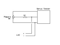
Worst case you may need to use a little 5v relay to open the throttle line. Usually the LVC pulls the wiper line to ground and we install a 1k resistor in series with the wiper to limit the current.
 
The throttle is a Astro Flight servo tester with a 5 volt regulator added. I removed the pot from the board and soldered the Magura wires to the remaining 3 terminals.

Matt
 
It's hard to say for sure, but something like this should work:Servo Tester LVC interface.jpg

The 1K pot is needed to prevent frying the opto coupler if the throttle is on full when LVC hits. If the input of the servo tester has a high impedance, the 1K won't interfere with normal operation. With some servo testers, the 1K might cause a problem, so test it with the resistor in line and make sure it still reaches full throttle and otherwise behaves.
 
thanks for dropping in Richard, appreciated.
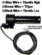
I dont suppose you know what colour wires are inside the Magura?
So i need to install a 1k resistor in series? to which cable?


D
 
Magura Throttle wiring.jpg

The 1K would go inline with the brown wire coming out of the throttle. I would try inserting the resistor and testing for proper operation. If it seems to work normally, then it should be safe to hook up the LVC line.
 
Hi D

Follow Fechters posts looks good to me :) I wouldnt stress so much about LVC keep and eye on your DB you should be good to go!! hoping you can tame that beast some and have some riding time now!! weather is so bad at the moment :evil: not much fun racing round the woods in this weather, you also got to make that bike of yours much more waterproof as well.

I have never noticed the Maguras grip being longer? on all my Maguras they are the same length as the throttle tube and plenty wide enough, I got big hands as well? :shock: I can really vouch from them as throttles mate, they are the best!! I have ridden mine it torrents of rain in fact you may as well have ridden in the river there was so much water and no problems, never had a single glitch dead spot nothing, they simply work brilliantly!

The only thing I will say the grip they fit as standard is very hard and not very comfortable however I always ride in padded gloves so this is not a problem and I may suggest with your bike and its tendency to want to spit you off the back you get some nice gloves as well :mrgreen:

Good luck with the throttle, really interested to see the thing tamed a little, I see that go pro are now selling a cut down version of their HD camcorder the hd hero 960, does pretty much all the same stuff as the bigger version except cuts down the 60fps and is only 960p is only $160!! still 960P looks darned good, this video was shot on it go watch you may have seen it, its pretty amazing!! watch in HD

[youtube]4aJzYioSDi4[/youtube]

Would love to see some RC footage from the woods some time soon!!

Knoxie
 
Many thanks Richard, appreciate you taking the time, i'll get a resistor in the morning and try it out.

Hi Paul,

It's not the Magura grip thats longer than the throttle tube, i just find the throttle too small, weird, if you and Luke and Matt have no issues then i must hold it incorrectly lol, still easily fixed and i'll have some comfy grips, never doubted the quality of the throttles workings just the grip and the length dont suit me.
I'm going to wire her back up and try to fab some sort of motor cover, i may as well spruce up the box too, i know what to do with the charger as Steve helped me out there :)
By the way i went to Brands on Friday, it was good to see Steve again and get a look at the bikes on the track, weather was appalling though - im getting the bike good to go for that one more dry spell ;) i'm confident that i can get her running sweet now, still the insane power as i have no way of limiting but at least it should roll on nice and smooth now.
By the way mate, i have room now for the quite large ANL holder - i plan to stick in a 150a (£15 from maplins!!!!) but i wondered, can i solder anything across the fuse to stop the viscious spark?? if so what rating??
i'm looking for a ride very soon so hopefully i'll be ready in the next few days, i'll post up the proposed wiring in pic form just incase im doing something stupid but the cabling is MUCH easier to read now.
i do have a flip mino for recording, so easy to use and does 720p - i'll give that a try first time i go out ;)
Look forward to catching up soon.


D
 
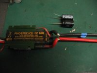
Why are the cap legs just wrapped around the ESC wires Deec? You do know they need to be soldered right?

KiM
 
hehehehe, yes mate i do, just haven't got round to doing it yet, thought you might have a look in and let me know if it was a bad location so i posted the pic unsoldered ;)


D
 
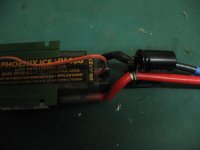
shall do mine right now and post pic here show you how i do them.

IMG_5867.jpg

IMG_5868.jpg


Ironically ever pic i took of the soldered joins is blured to the shithouse :-S
Keep the cap legs as short as possible Deec, i've left them long previously and they popped.

KiM
 
The lame plastic cover should be removed, and the cap leads should be soldered to the same solder points the wires enter the PCB.
 
i did consider that Luke but i was concerned i might shag the existing connections with my birdshit soldering ;)
tbh my voltage ripple on the brief outing i had was around 3v but i hadn't run long enough to see if that changed so im putting them on as a precaution, if kim posts something better i can always copy, thats why they are unsoldered.
Also i think the boards are a little exposed without the cover no?

D
 
fechter said:


The 1K would go inline with the brown wire coming out of the throttle. I would try inserting the resistor and testing for proper operation. If it seems to work normally, then it should be safe to hook up the LVC line.

I've used a Magura with one of your throttle boards, which has the 1k resistor already, and it works fine. The front-end of your circuit is pretty much the same as the AF servo tester.

-- Gary
 
liveforphysics said:
The lame plastic cover should be removed, and the cap leads should be soldered to the same solder points the wires enter the PCB.

I also tried this, dunno why but the solder on the power wires just doesn't want to take the solder i have it just resulted in a dry join, i wasn't even able to heat it enough with the Turbo Iron to remove the wires and redo with my own solder :-S doing it the way i have in above pics i dropped my ripple from 5v to under 2v with only one cap. Previously i had them soldered on a pcb board directly to the esc board. This above method worked for me, its how Recumpence did my HV100 so i'm sticking with it.

KiM
 
Kim,looks good to me mate, thanks.

Hi Gary, sorry im a little lost there, im not using Richards box with the hv160??
Thanks for dropping in btw, im hooking your LVC board straight to the magura and had no clue how to wire it up, Richard suggests this method for connecting up then connect the lvc if all is well?
tbh i still dont know what colour the lvc goes to? one to brown but whats the other colour Richard shows in the diagram?
Also - is it ok to hook my "kill" switch up to one of the wires? if so which one?

D
 
i could i suppose, but when i hit that 8kw my 123's dropped to something like 38v :shock: - just thrashing out whats possible here, no rush as the uk's soaked to the bone at the moment, so while im putting it back together i'd like to know what my options are, unlike lipo once the 123's hit lvc they drop like a stone toward cell reversal, being as my pack has had its fair share of negelct i'd like it in if possible, the kill also.
Either way should be ready to risk my ass again v soon ;) - will be ordering some more tyres again too, those 1.75" are bs, hopefully can get a 2.25" in.
One thing about your caps kim, did you sleeve right over the top? it looks its possible for them to short if the cables get squeezed?

D
 
deecanio said:
Kim,looks good to me mate, thanks.

Hi Gary, sorry im a little lost there, im not using Richards box with the hv160??
Thanks for dropping in btw, im hooking your LVC board straight to the magura and had no clue how to wire it up, Richard suggests this method for connecting up then connect the lvc if all is well?

D

Sorry, my point was that electrically, Richard's board, with the throttle input, is functionally identical to what Matt did by replacing the pot in the AF servo tester. His board also has the 1k resistor "pre-installed", and has the LVC connections. Anyway, if you hook it up like Richard showed above, it will work just fine.

Kim --

The whole point about having cell-level LVC is to keep from killing cells from abnormal conditions, like a parallel connection coming loose (it happens...). You can't just use a pack level LVC function because the cells hold their voltage up so well, that you could have one group of cells at 0V (i.e. -- dead...), and still not trip the pack level LVC setting.

-- Gary
 
deecanio said:
i could i suppose, but when i hit that 8kw my 123's dropped to something like 38v :shock: - just thrashing out whats possible here, no rush as the uk's soaked to the bone at the moment, so while im putting it back together i'd like to know what my options are, unlike lipo once the 123's hit lvc they drop like a stone toward cell reversal, being as my pack has had its fair share of negelct i'd like it in if possible, the kill also.
Either way should be ready to risk my ass again v soon ;) - will be ordering some more tyres again too, those 1.75" are bs, hopefully can get a 2.25" in.
One thing about your caps kim, did you sleeve right over the top? it looks its possible for them to short if the cables get squeezed?

D

Its actually only possible for them to touch if you broke both legs off either of the caps Deec...no there is no insulation over the individual joins...

No worries Gary... i check my pack each charge if theres a weak cell i'll catch it then with my u-beaut GGoodrum battery medic booster setupz :p :) good enough for me ... :)

So Deec...is this the second or third summer you have missed riding now LoL... :p

KiM
 
Hi Deec

Put your kill switch through one of the wires on the throttle just wire it in series like I did on your hall throttle, I reckon if you can you should also make good use of your case as a heatsink, get some thermal paste and bolt it down thats got to help.

Yeah Friday was a wash out, I go home on my e-bike at lunch time and after work I was wearing full waterproofs I got soaked :lol: I looked like a trawlerman in the high seas when I got off the bike, needless to say I didnt peddle once just stood up at 30mph all the way home! :? peddling gets you wetter! ha ha.

Good luck with the bike, post up with any issues
 
AussieJester said:
liveforphysics said:
The lame plastic cover should be removed, and the cap leads should be soldered to the same solder points the wires enter the PCB.

I also tried this, dunno why but the solder on the power wires just doesn't want to take the solder i have it just resulted in a dry join, i wasn't even able to heat it enough with the Turbo Iron to remove the wires and redo with my own solder :-S


And now you understand why I absolutely F'ing hate lead-free solder.
 
Even if you could get the wires off Luke, how do you suggest a cap be soldered to the negative and positive on the pcb where the '+' & '-' wires connect, seeing they are a good inch and a half apart, the legs of the caps would need to be extended to even reach. My first attempt as you know was to solder them directly to the top of the input leads resulted in a popping the legs hence my use of the 3 caps on a piece of pcb board which as we know was unsuccessful at ridding the high ripple. Its simply physically impossible to attach where you suggest Luke without lengthing the caps legs which defeats the purpose doesn't it?...

KiM
 
Back
Top