el_bassboi_sv
10 mW
I would first like to thank everyone on this forum and community, without you this project would not have been possible.
This is my first e-bike build, so every bit of information helps.
I was approached by a friend at work (Red_Liner740) to have an e-bike build-off a couple of weeks ago, so I decided to start with the Giant Rincon Disc that I owned as a frame.
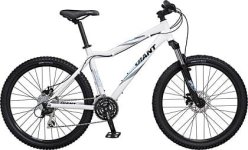
Thanks to (myzter) , I was able to get my eight 5s 5Ah 20C packs ordered along with a CA, Lyen's Extreme Modder 12 FET, Xlyte HS3540. While waiting for all my stuff to arrive, and going to grab Red_Liner740's new bike, ended up out of commission for 3 weeks after crashing the bike and badly injuring my ankle. Gave me more time to think and prep I guess...
Thanks to Lyen and electricwheels.de I was able to retrofit the HS3540 with HAL sensors.
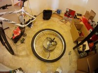
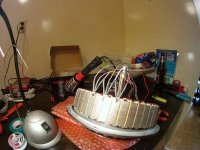
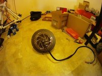
HALL SENSOR INSTALL INSTRUCTIONS
So after installation I came up with this,
Only to find the weather seal to have eaten through my HAL lines...
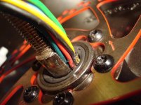
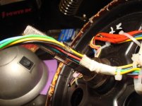
I guess the thing that threw me off was that at the plug the voltage would cycle 0-5v like it should, but it would short out ONLY when the motor moved as the seal would push the lines together...
Better in the house than out on the road...
more updates to come....
This is my first e-bike build, so every bit of information helps.
I was approached by a friend at work (Red_Liner740) to have an e-bike build-off a couple of weeks ago, so I decided to start with the Giant Rincon Disc that I owned as a frame.

Thanks to (myzter) , I was able to get my eight 5s 5Ah 20C packs ordered along with a CA, Lyen's Extreme Modder 12 FET, Xlyte HS3540. While waiting for all my stuff to arrive, and going to grab Red_Liner740's new bike, ended up out of commission for 3 weeks after crashing the bike and badly injuring my ankle. Gave me more time to think and prep I guess...
Thanks to Lyen and electricwheels.de I was able to retrofit the HS3540 with HAL sensors.


HALL SENSOR INSTALL INSTRUCTIONS
electricwheels.de said:Righto...
You've got the Stator in front of you, Hall Sensors inserted with the face up (the flat face with the 2 chamfered edges towards the outside) and epoxied in, facing you. Now trim these legs to 8 mm (5/16"), measured from the stator edge.
Connection of Hall Sensors
You've got 3 wires coming out of each Sensor:
- left - Positive (red wire) Vcc
centre - Negative (black wire) GND
The right side wire is the output wire.
On the left hand sensor goes the blue wire, on the centre sensor the yellow wire and the sensor to your right gets the green wire. Best is Spec 44 wire 28AWG. Take about 4 mm (5/32") of the insulation off and put some solder on the bare strands. Also put some solder on the hall sensor legs.
Now put the wire against the end of the hall sensor leg, and solder it together. The first 3-4mm of the hall sensor leg should be kept clear, so you can bend it easier.
Then you take some 20mm pieces of dia 1.2 mm shrinking tube, slide it over the cables until you hit the sensor body and heat them up till they're done. :wink:
Now go and find some gaps in the stator coils and thread these wire through. When you are done, epoxy the wires above the coils in.
Now wait till all is dry. File or sand off of the bits that stick out above the stator diametre.
Now connect all 3 red wires and solder them to a 24AWG wire, do the same with the 3 black wires.
The 3 other colors stay as single wires, just solder them to AWG 24 Wire of the same color.
That's basically it.
When you wire the cables to the Mini-XLR connector, you can use this wiring diagram.
http://electricwheels.de/electrical%20wiring%20diagram%20for%20Crystalyte%20hub%20motors.html
Good luck
So after installation I came up with this,
el_bassboi_sv said:HELP>>>
O.K. Had it all installed and did a trial (no load) @ 40v, no problems, great torque from the motor. Played with it for about 1 hr. Decided to try 60v, ran it to full speed (no load) and that was it... its as if a HAL went out or i hit my LVC (which i didn't). I switched back to 40v, and same thing, it will go about 2-3ft and cuts out as if it hit LVC/over torque. Let off the throttle and sometimes you can get it to move again, but, when you rotate the motor back even just a bit you get another 2-3 ft rotation out of it.
I checked the HAL sensors (at the controller plug). and when i spin the motor all 3 hals go from 0v - 5v between the Neg and Signal Lines.
Ive tried everything i could think of on Lyen's controller and CA settings. Im still getting the same thing.
I may just have to take apart the motor again
Any ideas?
Only to find the weather seal to have eaten through my HAL lines...


I guess the thing that threw me off was that at the plug the voltage would cycle 0-5v like it should, but it would short out ONLY when the motor moved as the seal would push the lines together...
Better in the house than out on the road...
more updates to come....


