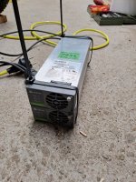
Emerson/Vertiv R48-series CAN programming?

Are you looking for how to talk to an RS485 transceiver chip with the ESP, or are you looking for a list of specific commands to be sent to the PSUs to get specific results?

For the former, there are libraries for some of the chips llike the MAX485 and MAX3485 (which itself comes on nice easy to use boards for stuff like this), and should be code examples in the libraries or within various other projects using 485 out there that you could borrow from, if you already know how to do ESP serial comms in general.

I don't know enough to tell if any are useful for this purpose, but there are a number of threads in the arduino.cc site about using 485, modbus, etc.

For the latter, I don't know a *complete* list of commands/etc., but there are a few in this thread, and some (possibly the same ones, as I didn't compare them) in other posts around the web about these PSUs that show up in a google search for them.

Hopefully others with more info on the commands themselves may chime in and/or post that info.
 
I had not found any CAN code in the Internet before I started to pick up messages from an Emerson / Vertiv controller.
All I found is listed in this thread.
Afterwards some other people started to work also with the Emerson/Vertiv rectifiers

Link to a Githup Project , not my project

If you find more usefull things about the rectifiers , please post it here.
Actually I´m investing not more time in this rectifier , because I found and have written down all I needed, and I can´t help you with ESP or Ardounio coding, as I do not know anything about it,

My next project will be the new Delta DPR3000B rectifiers, as they are smaller and have less weight.
 
Last edited:
I had not found any CAN code in the Internet before I started to pick up messages from an Emerson / Vertiv controller.
All I found is listed in this thread.
Afterwards some other people started to work also with the Emerson/Vertiv rectifiers

Link to a Githup Project , not my project

If you find more usefull things about the rectifiers , please post it here.
Actually I´m investing not more time in this rectifier , because I found and have written down all I needed, and I can´t help you with ESP or Ardounio coding, as I do not know anything about it,

My next project will be the new Delta DPR3000B rectifiers, as they are smaller and have less weight.
After many experiments you have done with emerson, eltek, huawei, etc, which PSU do you recommend for use as a charger, looking at its power, durability, communication, and when they are connected in series or parallel?
 
I have really tested a lot rectifiers.
Emerson , Vertiv, Eltek, Huawei, Tyco Lineage, Megmeet.
If you are using them in their upper voltage range (between 58-42v) they work all good.
But if you need them to work at 40V or lower than you have to look at their datasheets. Most of them start to reduce current under a certain voltage or even turn off.
If you hook them up in series this problem will even get bigger, as one cpuld work at the upper voltage limit and the other drops down abd reduces the current. The only which is not really reducibg current is the vertiv R48-2000e3.
Here you get 35A down to 20V which is 83% of the max current.

So there is no easy good or bad.

You have to know what you want to do, how much power you need and then decide what to use.

Power to weight ratio is very good on Eltek Flatpack S 1800W , Vertiv R48-2000E3 and R48-3500E3 and R48-4300, also on the Huawei R4875.
But most of them reduce their current at lower levels.

I use two Vertiv R48-2000E3 in series for charging my 21S battery from a 230V 16A outet.
For faster charging i use two R4875G5 on two phases, but at low soc levels they reduce to 55A.
 
Last edited:
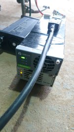
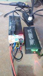
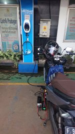
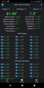
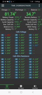
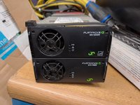
today i tried charging at an ac charging station with a new setup, vertiv r48-2000e3 and emerson r48-1000 in series. the battery only draws 7.5a, the same as the previous 2x r48-1000 setup. finally I paralleled it with a 24s lifepo4 charger 10A to get close to 1C. I'm still confused, is the battery capacity really limited to only drawing 7.5a (0.3 C) if charging using a PSU? or is there something abnormal?

Battery lifepo4 24s 22ah cylinder.
Charge 1C
Discharge 3C
 

Attachments

  • DSC_0752.JPG
    DSC_0752.JPG
    1.6 MB · Views: 12
  • DSC_0751.JPG
    DSC_0751.JPG
    1.8 MB · Views: 12
  • DSC_0750.JPG
    DSC_0750.JPG
    1.6 MB · Views: 16
  • Screenshot_20240122-181300.png
    Screenshot_20240122-181300.png
    507.9 KB · Views: 15
  • Screenshot_20240122-180947.png
    Screenshot_20240122-180947.png
    504.2 KB · Views: 15
today i tried charging at an ac charging station with a new setup, vertiv r48-2000e3 and emerson r48-1000 in series. the battery only draws 7.5a, the same as the previous 2x r48-1000 setup. finally I paralleled it with a 24s lifepo4 charger 10A to get close to 1C. I'm still confused, is the battery capacity really limited to only drawing 7.5a (0.3 C) if charging using a PSU? or is there something abnormal?

Battery lifepo4 24s 22ah cylinder.
Charge 1C
Discharge 3C
I just bought 2 r48-3000e3 and plan to set the each voltage 42V 20A, connected in series to make 84V 20A charger for my Polytron Fox R. Did You had set the current limit trough CAN BUS?
 
today i tried charging at an ac charging station with a new setup, vertiv r48-2000e3 and emerson r48-1000 in series. the battery only draws 7.5a, the same as the previous 2x r48-1000 setup. finally I paralleled it with a 24s lifepo4 charger 10A to get close to 1C. I'm still confused, is the battery capacity really limited to only drawing 7.5a (0.3 C) if charging using a PSU? or is there something abnormal?
No, I don't think your battery is limiting, but your R48-1000 runs at a voltage level where current is limited and the R48-2000e3 in series then can only give the same current. If you have two R48-2000e3 the will only limit to 35A if the voltage from one of the supplies drops and the other rises.
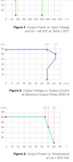
Here is the voltage / current chart from the R48-2000e3
Screenshot_20240122_181545_Drive.jpg

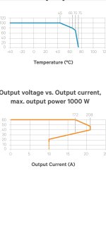
And that is the chart for the new R48-1000e3, sorry have no chart for the older version
Screenshot_20240122_181910_Drive.jpg
The other Vertiv Rectifiers have more current limiting when the voltage drops under 35V then the R48-2000e3.
Check the voltage level of euch psu and then you will see that they are not equal and the one with the lower outup voltage is limiting output current.
 
Last edited:
I just bought 2 r48-3000e3 and plan to set the each voltage 42V 20A, connected in series to make 84V 20A charger for my Polytron Fox R. Did You had set the current limit trough CAN BUS?
The limits have to be sent through CAN BUS
 
I just bought 2 r48-3000e3 and plan to set the each voltage 42V 20A, connected in series to make 84V 20A charger for my Polytron Fox R. Did You had set the current limit trough CAN BUS?
Yes om... i set current limit both PSU to 1,20%.

And this my sketch on arduino for your reference. Using mcp2515 and esp32.

// CAN Send Example
//


#include <mcp_can.h>
#include <SPI.h>


MCP_CAN CAN0(5); // Set CS to pin 5


void setup()
{
Serial.begin(115200);


// Initialize MCP2515 running at 8MHz with a baudrate of 125kb/s and the masks and filters disabled.
if(CAN0.begin(MCP_ANY, CAN_125KBPS, MCP_8MHZ) == CAN_OK) Serial.println("MCP2515 Initialized Successfully!");
else Serial.println("Error Initializing MCP2515...");


CAN0.setMode(MCP_NORMAL); // Change to normal mode to allow messages to be transmitted
}


byte data1[8] = {0x03, 0xF0, 0x00, 0x21, 0x42, 0x2E, 0x00, 0x00}; // voltage 43.5v


byte data2[8] = {0x03, 0xF0, 0x00, 0x24, 0x42, 0x2E, 0x00, 0x00}; // voltage 43.5v


byte data3[8] = {0x03, 0xF0, 0x00, 0x19, 0x3F, 0x99, 0x99, 0x9a}; // current 20a


byte data4[8] = {0x03, 0xF0, 0x00, 0x30, 0x00, 0x00, 0x00, 0x00}; // output on


byte data5[8] = {0x03, 0xF0, 0x00, 0x32, 0x00, 0x01, 0x00, 0x00}; // walkin on


byte data6[8] = {0x03, 0xF0, 0x00, 0x29, 0x44, 0x7A, 0x00, 0x00}; // walkin time 10s


// 42 2E 00 00 = 43.5v
// 42 48 00 00 = 50v
void loop()
{
byte sndStat =CAN0.sendMsgBuf(0x06080783, 1, 8, data1);
CAN0.sendMsgBuf(0x06080783, 1, 8, data2);

CAN0.sendMsgBuf(0x06080783, 1, 8, data3);


CAN0.sendMsgBuf(0x06080783, 1, 8, data4);

CAN0.sendMsgBuf(0x06080783, 1, 8, data5);


CAN0.sendMsgBuf(0x06080783, 1, 8, data6);
if(sndStat == CAN_OK){
Serial.println("Set Succesful !");
} else {
Serial.println("Set Failed...");
}

delay(5000); // send data per 5s
}


/*********************************************************************************************************
END FILE
*********************************************************************
 
If you have two R48-2000e3 the will only limit to 35A if the voltage from one of the supplies drops and the other rises.
Thank you friend. if the problem is in the r48-1000 then I will try setup 2x r48-2000e3 and hope that the current can be close to 1C.

Sorry have no chart for the older version
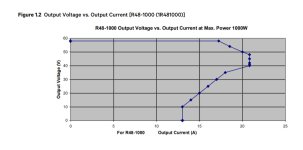
I found chart for r48-1000
 

Attachments

  • _20240123_004903.JPG
    _20240123_004903.JPG
    51.4 KB · Views: 2
According to this chart it should only limit to 17-15A
Have you set both to maximum current? 1.22
Later I will go and set up a Vertiv R48-2000E3 duo to charge my scooter and we will see what happens.
My battery can easily take 100A and more.
 
Last edited:
According to this chart it should only limit to 17-15A
Have you set both to maximum current? 1.22
Later I will go and set up a Vertiv R48-2000E3 duo to charge my scooter and we will see what happens.
My battery can easily take 100A and more.
Yes i have set both to 1.20% current limit with offline command (default), along with setting output on, walking time, default voltage. and everything seems to work.

I use this command for set current
03 F0 00 19 3F 99 99 9a (1.20%)
 
Just checked charging on my scooter.
Sorry for the cable tie setup.
I have 230V mains. Probably you are on 120V and get only the half output current?
20240122_204612.jpg

Screenshot_20240122_204535.jpg

And that is a 24V plus 48V in series setup which holds it output power from empty to full, because the rectifiers work in their upper voltage range.
20240122_204433.jpg
 
Last edited:
Should also have full power on 220V mains. Mine where also running on a single phase.
 
Hi guys,

I have purchased four Vertiv R48-3000e and they where supposed to come set to 54V but they came with 48V. I was reading this thread but I don't find any information about the device used to read and send CAN messages to this charger. Could you please post a link with this device? Can anyone post a whiring diagram?

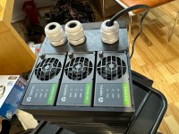
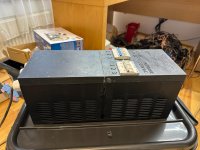
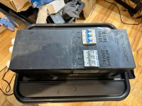
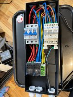
I have designed an enclosure that can be 3d printed and can hold 3 chargers with breakers and all. I attach a few pictures so if anyone is interested I can post the stl files. This can be hang on the wall or used as stand alone device with a power of 3kW that's not bad for the size.

Cheers and thank you.
Daniel
 

Attachments

  • IMG-20240123-WA0001.jpg
    IMG-20240123-WA0001.jpg
    243 KB · Views: 10
  • IMG-20240123-WA0002.jpg
    IMG-20240123-WA0002.jpg
    184.3 KB · Views: 8
  • IMG-20240123-WA0003.jpg
    IMG-20240123-WA0003.jpg
    183.4 KB · Views: 8
  • IMG-20240123-WA0004.jpg
    IMG-20240123-WA0004.jpg
    218.9 KB · Views: 9
  • IMG-20240123-WA0005.jpg
    IMG-20240123-WA0005.jpg
    238.5 KB · Views: 10
You need a USB to CAN adapter and the software that comes with the adapter.
I use a canalyst II , but you do not need a two channel device, so you can buy a cheaper one. A cheaper one would be usb2can, but I do not know the software from the cheaper ones.

Wiring diagramm is not needed.
You need to connect CAN-low and CAN-high from your Vertiv to the USB-CAN adapter, set in the software the right can speed 125kbs and probably you need to set a jumper for the 120 Ohm resistor on the USB-CAN adapter.
Then the software should show CAN traffic and you can start sending messages. Biggest problem will be the understanding and the use of the software, when you never have done anything with CAN.
Probably someone has a link to a video tutorial for first steps with CAN.
 
Last edited:
You need a USB to CAN adapter and the software that comes with the adapter.
I use a canalyst II , but you do not need a two channel device, so you can buy a cheaper one. A cheaper one would be usb2can, but I do not know the software from the cheaper ones.

Wiring diagramm is not needed.
You need to connect CAN-low and CAN-high from your Vertiv to the USB-CAN adapter, set in the software the right can speed 125kbs and probably you need to set a jumper for the 120 Ohm resistor on the USB-CAN adapter.
Then the software should show CAN traffic and you can start sending messages. Biggest problem will be the understanding and the use of the software, when you never have done anything with CAN.
Probably someone has a link to a video tutorial for first stets with CAN.
Thank you Dominik for the fast and comprehensive response. I will keep you posted. All the best.
 
You need a USB to CAN adapter and the software that comes with the adapter.
I use a canalyst II , but you do not need a two channel device, so you can buy a cheaper one. A cheaper one would be usb2can, but I do not know the software from the cheaper ones.

Wiring diagramm is not needed.
You need to connect CAN-low and CAN-high from your Vertiv to the USB-CAN adapter, set in the software the right can speed 125kbs and probably you need to set a jumper for the 120 Ohm resistor on the USB-CAN adapter.
Then the software should show CAN traffic and you can start sending messages. Biggest problem will be the understanding and the use of the software, when you never have done anything with CAN.
Probably someone has a link to a video tutorial for first steps with CAN.
I did it :) .... thank you for the advice. I have set all the parameters successfully. Did anyone develop a arduino board - program that can talk to these chargers?

Cheers,

Daniel
 
found another problem with the psu, the voltage could not be set above 48v, when I tried to set it to 49v - 58v the psu instead changed to 43.5v. i tried it on r48-2000e3 and r48-1000, online and offline commands. both same respond
 
found another problem with the psu, the voltage could not be set above 48v, when I tried to set it to 49v - 58v the psu instead changed to 43.5v. i tried it on r48-2000e3 and r48-1000, online and offline commands. both same respond
Hi, to set the voltage as permanent you have to use the line of commands in the first posts and let the can reader send it at least twice, I let it do it for ten time for each message.
 
Hi, to set the voltage as permanent you have to use the line of commands in the first posts and let the can reader send it at least twice, I let it do it for ten time for each message.
Thanks for the reply, maybe I gave the wrong command, I'll try again.
 
That sounds strange to me.

Probably you have send a command to set a lower overvoltage protection voltage.
I do not know what happens when you set the ovp to 48V and you want to set 49V output voltage afterwards.
 
That sounds strange to me.

Probably you have send a command to set a lower overvoltage protection voltage.
I do not know what happens when you set the ovp to 48V and you want to set 49V output voltage afterwards.
I'm making a project using serial Bluetooth and managed to set the DC output on, limit current, voltage 41v - 48v, except that setting the voltage above 48v didn't work. for example, if the psu voltage is 41v then I set it to 48v it immediately changes. but from 48v to 53v it gets 43v instead. I also feel strange. below are the commands I used, could there be something wrong?

byte data15[8] = {0x03, 0xF0, 0x00, 0x21, 0x42, 0x56, 0x00, 0x00}; // voltase
byte data16[8] = {0x03, 0xF0, 0x00, 0x24, 0x42, 0x56, 0x00, 0x00}; // voltase

if(cmd == '10'){
CAN0.sendMsgBuf(0x0607FF83, 1, 8, data15);
CAN0.sendMsgBuf(0x0607FF83, 1, 8, data16);
 
The commands are ok.
Probably you set the new ovp before, or it was already set
 
Back
Top