• Howdy! we're looking for donations to finish custom knowledgebase software for this forum. Please see our Funding drive thread

Even Newer 4 to 24-cell Battery Management System (BMS)

ejonesss said:
in a future version it would be nice if everything related to charging (charging, and lighting up the leds ) was powered from the charger.

You can do that now if you use a small separate 12v power supply and disconnect the pre-regulator and switch transistor. This is definitely recommended for higher cell counts (over 24).

I orginally tried making the control circuit regulator run off the entire pack, but the heat dissipation on the regulator was excessive.
 
I have a V2.2 board that I run at 100.8V
I power the 12V circuit from a separate supply.

-methods
 
Great!
The schematic is not coming full on the screen. half is cutting off. Could you fix it
Tinny
 
Right hand click
View Picture

or

Right hand click
Save Picture as

-methods
 
fechter said:
You can do that now if you use a small separate 12v power supply and disconnect the pre-regulator and switch transistor. This is definitely recommended for higher cell counts (over 24).

I orginally tried making the control circuit regulator run off the entire pack, but the heat dissipation on the regulator was excessive.

I'm planning a charging supply of a 12V and 48V in series, so this is perfect for me. However, I'd also like to be able to charge from a standard charger (Zivan, Soneil, etc.) using the batteries to power the charge control. Here's my question: is there any harm in powering the circuit (downstream of the regulator) without disconnecting the upstream devices? I would either connect the tapped 12v or supply the ground in the original design (and the connector would prevent both).

I've several of these boards; thanks for your efforts!
 
I'll have to think about that one. I don't think you can backfeed the regulator section, but you might be able to feed between the pre-regulator and the 78L12 or just ahead of the pre-regulator. This part of the circuit may vary depending on which version you have.

Otherwise you could add a small diode somewhere in series with the regulator and feed downstream of the diode. The control circuit needs at least 10v, but not over 20v.
 
They are all v 2.3 boards. I thought about the diode, but that would be a tricky retrofit, somehow sandwiched between the 78L12 and the board.

Further thoughts?

Thanks!
 
I think you definitely need a diode in there if you want to source it from an external supply. Transistors don't like reverse polarity. I don't really know what happens if you backfeed a 78L12, but I'd guess it would be unhappy. I should try it sometime to see what happens.

I was thinking to lift the transistor out, fold one leg up and stuff the diode into the hole where the leg went, then tie the folded leg to the other side of the diode. Standard dead-bug approach. If you do this to the collector lead of the pre-regulator, then the flying connection will be where you can attach your 12v input wire. You could also do this to the input leg of the 78L12.
 
Hi!

Can anybody tell me something about the changes in version 2.6 an the reason(s) for them?

regards
Manfred
 
The feedback on the control circuit was reconfigured to give a lower PWM frequency when throttling. This should reduce FET heating a bit and makes the bi-color LED easier to read at low duty cycles. This should also make the auto-shutoff feature a bit more reliable and it eliminates one other capacitor in the control circuit. The lower frequency might behave better with some chargers as well. The frequency can be pretty much controlled by changing the value of one capacitor now (it could be increased again if desired). The old setup could run as high as 20khz. The new configuration is more like 200hz.

The values for the LM431 divider resistors were changed to bring the voltage down a bit. The old ones ran around 3.7v, which is a bit high. I get around 3.67v with the new values. These are all subject to component variations in both the resistors and the LM431s. This is just a component value change, not a layout change.
 
Hi everybody,
I need help, I just finished the BMS 2.3 but I have a problem . I have already test the LVC (TC54VN), the 16th are ok. But when I plug the charger(no cells hook up), all the orange leds lit in a split second and then turn off. The main led is still green. The reference voltage on LM431 of the cells 5, 6, ….16 is 2.3V instead 2.5V, so LM431 are not trigged (the voltage is 3.7V on each unit cells except unit cells 1,2,3,4). The resistors of the voltage divided are well 75K and 180K.
On the unit cells 1, 2, 3, 4 the voltage is only 0.3V ! I don’t understand what’s happen. I check the space of each components. All seem well be placed.
The voltage charger is 61.5V.
I attach photos with the voltage measures.( It's not my board on the photo)
Is someone have an idea ?
Thank you in advance
Michael
[ATTACH type="full" alt="Voltage BMS Measure.jpg"]25229._xfImport[/ATTACH]
[ATTACH type="full" alt="Voltage BMS Measure 2.jpg"]25230._xfImport[/ATTACH]
 
From just a quick read of your post, it seems that your board is working correctly. If you hook up the board without the batteries connected the orange LEDs light for a split sec then the main LED turns green.
 
This morning i test with a power supply lab each unit cell. I adjust the voltage to 3,7V and set it between each unit cells one after the other, and all the orange leds light.
So i think the 16th unit cells are ok, but i found strange why i don't have 3,7V on the 4th first cells when i plug the charger only.
Do you think i can hook up the batterie ?
 
It sounds like it's working correctly.

When the main LED is green, the charging current is turned off by the throttling circuit, so the cell LEDs will go out and the voltage across them will drop.
If you put a jumper across any one cell (above cell 4), the auto shutoff won't trip and you can measure individual cell voltages. You can move the jumper to check the one that was jumpered first.

The power for the control circuit comes off a tap on cell 4, so the voltage there can be lower due to this drain. This won't matter once you attach the cells.

It sounds OK to try attaching the cells. Just be very careful about the wiring.
When attaching the cells to the board, be sure the charger is not attached.
 
Can I use Ceramic reisistor like this http://www.rcl.lt/index.php?id=2&lang=lt&begin=1&acc=show&fid=687&pcode=R0685&pmode=&frame=3 instead of metal film? It's like 10x cheaper. I want to get BMS parts my self cause this BMS is getting expensive. Only 100$ spent for board witch include taxes and shipping. And parts if I buy from mouser with shipping and taxes getting near 170$ and parts are only 80$ from them. So, it's almost like 300$ for BMS which you must made your self. And half of that money go f... :( you know. So, I am looking for a cheaper way and trying to get parts in my country. Of course, I met difficulties like that most of the parts I have to order from local electronic parts shops which they don't have it. And for this reason I am looking for more frequently usable parts which they have (in pasive parts and maybe a few from active). This way maybe I can change amount of parts which I need ordering by special order. Maybe can I use different capicators like electrolyte ones in 2.6 bms? I have V.2.5 board, but looking for parts like in V.2.6.
 
Thanks Nate and Fechter for your answer
I do the first charge and all seem OK. :D
I have Just another question. Is it normal that the main LED still light green even when the charger is unplug ?
 
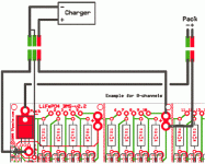
No, it should go out. Did you wire the charger to the BMS with a 3 prong connector? Make sure you didn't connect the two negative leads, the small and big wires, on the BMS side. They should only connect on the charger side. Look at the two green connectors that are side by side in the picture below. * Note the picture shows a 2.2 but it is the same for the 2.3.
BMS.gif
 
Karolis said:
Can I use Ceramic reisistor like this http://www.rcl.lt/index.php?id=2&lang=lt&begin=1&acc=show&fid=687&pcode=R0685&pmode=&frame=3 instead of metal film? It's like 10x cheaper. .... Maybe can I use different capicators like electrolyte ones in 2.6 bms? I have V.2.5 board, but looking for parts like in V.2.6.

Yes, you can use those resistors. Yes, you can use electrolytic capacitors.
 
Thanks Nate . I connect the strap at the side of the femal connector instead of strap the Male XLR of the charger :oops:
This time all seem good. :D
 
Karolis said:
Can I use MPSA92, MPSA42 instead of KSP94 and KSP44 transistors? Also Can I use 2N5064 instead of 2N5060 SCR?

Those should work fine. Just double check the pin configurations to make sure they are the same.
 
Hi !

I have assembled a 40 cell BMS based on the v2.3 to use in my EV (Renault Clio Electrique).
I have 40 TS-LFP160ah that I would like to charge and balance using this BMS, also the LVC function is needed for me.

The Charger that is used is the original charger with a Ni-Cd profile. I uses constant power in the first fase, giving somewhere between 15A and 25A depending on setting. (It can be set to draw 10A or 16A from the 220V line).
In the second fase it uses constant current of about 4A. This is a little bit to high to keep the cells in balancemode when the first cell starts shunting. (I have 3.9ohm, 1A shunts).
Therefore I need to try to get the PWM part working to see if the charger will accept that. I have tried to connect everything and what I find is that when I connect the ground for the control part the led turns on green directly and it seems that the FET does not conduct. (I can see that the charger tries to output but it turns off in an instant.)
What could the problem be ? Shouldn't the led turn on red to start and the turn green when all shunts turn on.
None of the shunts are on when I connect the small ground to the charger minus. I have tested all the shunts, and all the LVCs, but I have problem testing the main function. I dont have any source to adjust the input to the BMS to simulate the charger, Do i have to test the whole range of the BMS to see if the main logic is working ? What I'm aiming at is to maybe add voltage to the first 8 channels and test that the BMS main parts work correctly. Is that possible when I have all channels populated ? or do I need to remove anything ?

What could the problem be ?
Struggeling with this for a couple of weeks now.
Could there be any of the Optos that gives this behaviour ?

Best Regards
/Per Eklund
Sweden
Renault Clio Electrique with new 20,5 kwh TS-LFP pack, (first LiFePo Clio in Sweden).
 
Hey Everyone,

I am having a problem with one of my v2.3 bms boards. The light on the main channel will not switch to completly to green. I notice the light switche amber when approching the cutoff mark .. It seems like its trying to switch to green however says greenish-amber, and will not shutoff the bms.

I've changed almost all compnents on the main channel; however i have not got it to do anything differently.

If anyone could guide me on where to check for issues it would be much appreciated.

the only part i really can't test is the part labeled " ild2 v748h68"

thanks
-steveo
 
Back
Top