Even Newer 4 to 24-cell Battery Management System (BMS)

i like the idea of a toaster ,or toaster oven.
they have the handling safety already "designed in ".
again ,these kinda things are NOT for the novice,and i DO use my e-bike as
Primary transport means. i keep a trio of Spare packs!
the next build will "look" nice.all 4 of my previous were obviously
experimental.
i am here ,because i want to try 100 volts ,with a throttle scheme i came up with
after using e-braking,and a kelly ,with enough margin of power to be depended on
in experimental observation of the x5303 ...(front)
thanx ALL!
 
Lightbulbs can work surprisingly well as current limiters, because their resistance curve is non linear. they'll offer little resistance to a light load, but will increase drastically when they reach their rated wattage.

I have an electrical box wired with 2 outlets in series for testing electronics. I can plug a lamp / toaster / kettle into one outlet, and my test load into the other. It'll often keep from blowing up parts when troubleshooting repairs. It's also useful for anodizing titanium. If I short the Ti to the cathode, the lightbulb just comes on. no damage done.

Of course, using it for battery charging is going to be inefficient compared to trimming the voltage down via the feedback pin. Most power supplies are quite simple. Find the TL494 (or equivalent usually 8 pin pdip), and look for the reference voltage (normally 2.5v) Drive that voltage up, and the output voltage falls.

That's how the little meanwell charge controller widget works, and it should work on pretty much any switching supply, assuming there's not too many supervisor circuits getting in the way(PC power supplies have gotten bad for this in the past several years).

Regarding charging the SLA off the line.. I believe doing that without an isolation transformer is normally considered a Bad Thing(tm)
 
it's not for the absent minded,or faint of heart either...
i cant agree more,but in a pinch,it was just what i needed. my soneil charger failed.....
and strangely enough , the sla pack that i began using this way is going into a third year of service...
they came with my first 72volt x5303 setup
i now use a regulated p/s,but i still have circuit ,just in case.
yes i will use transformers in any future such schemes.....
 
you would want to use a 'isolation transfomer'
Which is basically a 1-to-1 transformer. You put in 120V and you get out 120V. But the advantage is that the two circuits (input-to-output) are electrically isolated just like any other transformer.
Thus there is no common ground when you put such circuits in series.

So the method of connection would be : OUTLET ---> ISOLATION TRANSFORMER ---> CHARGER ---> Battery

You can buy these transformers off ebay, and they are dirt cheap(about 20-50$ or so .. maybe I lied a little :p ). But before you buy them, check that they match your wattage. If you are using a 100W charger, you would want a 100W or greater isolation transformer.
Most of the isolation transformers on ebay that are around the region of $1-$10 are transformers which are to isolate your phone line from the phone or some sort of signal wire(cables, DSL etc etc); and you dont want those.
 
kadir said:
you would want to use a 'isolation transfomer'
Which is basically a 1-to-1 transformer. You put in 120V and you get out 120V. But the advantage is that the two circuits (input-to-output) are electrically isolated just like any other transformer.
Thus there is no common ground when you put such circuits in series.
What's more important is the safety aspects of it. when a circuit is isolated, you need to touch two points in the circuit in order to get a shock. without isolation, any other piece of equipment, or the chassis of the charger itself can act as a return.

As an example, when I anodize titanium, I use an Isolation transformer, followed by a variac and a rectifier/cap to get the 0-120VDC needed. I can touch either the workpiece or the cathode safely, as long as I don't touch both at the same time. I generally don't touch either very much, but the odd time I do it doesn't matter. Additionally, any contact between a single live part of the circuit and ground will do nothing.

If I had skipped the iso transformer and just used the variac alone (a variable tap autotransformer) touching the anode while I'm adjusting the voltage on the variac will likely cause a really bad shock. Any live part of the circuit touching ground will create a short, and potentially a shower of sparks/fire etc.
 
i'm looking for a BMS for my 28S !! Its Lifepo4 ... I currently have the 2.6 and now the charge controller is defect im looking for a brand new BMS !! What i have to buy if i want balancer + HVC + LVC ????

Tanks for reply
 
It's coming, but we ran into a couple of issues, mainly with the HVC triggering and interaction with the charge controller logic, as it applies to PSI LiFePO4 cells. Andy discovered the problem, and I'm in the process of duplicating his test setup, so that I can see what is happening. Also, he managed to get the relay-based charge controller to get stuck with the relay latched in the wrong position. While I'm working on the HVC trigger issue, Richard is working on a relay-less charge control scheme.

The shunt portion of the circuit continues to work reliably, as does the LVC logic. Once we get the HVC/charge control issue sorted out, we should be good-to-go, and I'll try another test run of boards.

Stay tuned...

-- Gary
 
Tanks for the reply !! I just have last question ... if i'm interessed to get PRÉ assembled and tested BMS for 28S of Lifepo4 it it possible ?? with a case if possible ! I dont care about the price !! I need a BMS Fast :D I think i can test the first release of the STABLE version !! I will pay a good price for this privilege !!

Very big Tanks

Chris
 
Is there really no way to prototype your own PCBs? You guys must have spent a small fortune printing all these boards by now.
 
GGoodrum said:
It's coming, but we ran into a couple of issues, mainly with the HVC triggering and interaction with the charge controller logic, as it applies to PSI LiFePO4 cells. Andy discovered the problem, and I'm in the process of duplicating his test setup, so that I can see what is happening.
Yes - there is a problem with the HVC detector portion. Unfortunately, while it properly recognizes the ~3.7V point on the bench with no cells attached, it does not work with cells attached. While it's true that my main test pack is PSI cells, the malfunction is the same regardless of the cell manufacturer. With cells attached, the HVC doesn't trip even when cell voltages rise to 4.2V. If the resistor divider is adjusted to bring the trip point lower, the HVC activates immediately at 3.6V as soon as the shunt activates (instead of when the shunt is at maximum current).

GGoodrum said:
Also, he managed to get the relay-based charge controller to get stuck with the relay latched in the wrong position.
Oy. I "managed" to get the relay-based charge controller to get stuck by simply using the BMS as it was intended. The device works perfectly with a balanced pack. Unfortunately, if the pack's always balanced, there's not much need for a BMS... :( With an unbalanced pack, and with the HVC activating as soon as the shunt activates, the relay trips and then releases. It will do this for just under 43 minutes.*** At this point, the charge controller LED goes green, the relay latches 'on', and the charger pushes current into the pack unchecked until the shunts are swamped. That's when things get really hot, solder flows, and cells are destroyed. Hell, I can do that with a pack without spending the time and money to build a BMS. ;)

In addition, I'm not happy with the way the charge controller operates. It requires a 'start' button press at the beginning of the charge, but the relay immediately closes even with no 'start' button press. This means that the pack is getting fed from the charger immediately, but the HVC sensing electronics are not yet 'on line' and cannot protect the pack. To make it more challenging, I was unable to activate the charge controller with the start button if a cell is already too high and the shunt is activated - the HVC keeps the controller from starting normally. This would be great if the relay didn't automatically close, but as it is, this is yet another condition where the pack cannot be protected from overcharge. And it makes it impossible to use this device to balance an out of balance pack.

Step away from the stage - there's no fat lady warming up yet...

edit... *** It appears that the controller didn't fail after 43 minutes, but the opto for the high cell failed. I don't have enough information to blame either the opto or the circuit as channel 4 failed - and this channel has been the guinea pig for all the resistor changes and other fiddling.
 

Attachments

  • 4_3_3_Balance_Test_2.jpg
    50.4 KB · Views: 1,175
To be clear, the HVC function has worked fine on several variants. I've used it on a number of LiPo-based setups, and at least one a123 LiFePO4 configuration. Richard has also used it on a special BMS that he did for one of the electric motorcycle companies. Andy was the first to try it with PSI cells, and he had issues. I'm in the process of duplicating his test setup, so that I can try and see what he saw.

Richard believes the problems Andy was seeing are more control section related, not the HVC tripping. In any case, he's busy working on a new control scheme, that is relayless, and eliminates the requirement for a start/reset button. In the meantime,I will verify the proper operation of the cell circuits and the HVC trip point logic.

-- Gary
 
from the pSI home page

Although fuel cells today are being mass produced and their various components are commercially available, the detailed processes taking place in the cells are in many cases not yet fully understood.

:?
Can we LiFepo4 people go ahead or volunteer or further testing ? I have two types, a123 and a pack type.

There are plenty of chargers etc out there restricted to certain types of batteries. Does this have to be a one type fits all device???
 
While we are waiting can anyone recommend a single cell charger I can use to keep my pack balanced after getting it nearly charged with my 24V charger??
 
GGoodrum said:
To be clear, the HVC function has worked fine on several variants.
It doesn't matter unless you want to use one of the earlier variants. I can confirm that the HVC works correctly on the 4.1.5 board I tested. But sometime after 4.1.5, you chose to change the shunt activation to a 'by exception' norm instead of a 'shunts on at end of charge' method. In addition, capacitors were added and/or moved around. Bottom line - the 4.3.3 channel is NOT the same as the 4.1.5 -- so one should not assume that 4.3.3 will work because 4.1.5 does -- because I can absolutely confirm this is NOT the case.

GGoodrum said:
I've used it on a number of LiPo-based setups, and at least one a123 LiFePO4 configuration. Richard has also used it on a special BMS that he did for one of the electric motorcycle companies.
I was involved in the special BMS - this unit is based on the V4.1.5 channel and is different from the 4.3.3 channel. Therefore, it doesn't have a thing to do with this problem.

GGoodrum said:
Andy was the first to try it with PSI cells, and he had issues. I'm in the process of duplicating his test setup, so that I can try and see what he saw.
Again - different BMS circuit therefore different results. If only someone had tested the 4.3.3 variant before I started what I thought was beta testing... :shock:

The control section is a completely different problem. It appears that the opto blew at the 43 minute mark, not the control section.

I've just removed the parts added to the circuit from 4.1.5 to 4.3.3 and had to replace the channel 4 ILD2 which died during the test. And I have a fully-functioning board with a functioning HVC. I'll torture test the control section again once I change some voltage divider resistors and run another endurance test with an out of balance pack.

In the mean time, here's test video for the V4.3.3 board. This test was designed to force at least one HVC signal so I could measure the cell voltage when the HVC triggers. This was the second 4S section of board I built and it behaves exactly like the first 4S section I torture tested. Again - the behavior and function is identical and consistent.

The 4S pack was fully charged and balanced, then 1Ah was removed from the pack. Voltphreak single-cell chargers brought cells 1 and 4 up to 3.7V. I had to manually discharge 1 and 4 a bit to below 3.6V so the shunt did not immediately trigger. As can be seen, cell 1 (with a stock channel) shunted first, followed by cell 4. Channel 4 had been modified with a lower voltage divider resistance - 3.7V positively triggered the HVC with no cells attached. With a cell attached, the HVC activates at 3.6V as soon as the shunt LED triggered. The stock channel 1 did not trigger the HVC at all even when a cell was allowed to charge to above 4V.

[youtube]pkNnplBp2h8[/youtube]


When you get a channel that works (AKA V4.1.5), leaveitthehellalone! :shock: :D
 
It seems that under some conditions the shunt circuit can still oscillate, which has been a longstanding problem. Of course this oscillation screws up everything. Layout, including cell wires and the cells themselves will affect the oscillations. What I want is something that either can't oscillate no matter what, or one that oscillates in a controlled manner that does not interfere with the desired operation.

This has been incredibly frustrating for everybody. A circuit that works perfectly on my bench blows chunks on Andy's bench and vice versa.

In this long, brutal learning curve, I have come across a few nuggets. It looks like I may have found a solution for the pesky auto power switch scheme. Maybe not a big deal, but something I've been trying to work out for years. Basically a way for the control circuit to automatically turn itself off when the charger is off and turn itself back on when the charger is on by sensing the charger voltage. Pretty much all the other setups need a 3rd wire or a separate power supply to keep the control circuit from draining the pack.
The cascaded signalling setup has great potential for extremely low drain and some fail safe features, along with one wire connection.
Eventually it will get where I want it, or it will kill me. :shock:
 
Stevil_Knevil said:
Anybody got a few 'Even Older' Goodrum/Fechter 24-cell boards laying around :?:

Please PM 8)

Contact Andy

He have some i think

I bought two from him ( the V2.6)

Doc
 
Testing continues on the latest single board BMS -- and it's looking very good indeed!

A properly sized capacitor made all the difference in the world - Richard appears to have completely solved the LM431 oscillation challenge that's been abusing this project for more than a year. Once the CAP was added, the channels fell completely and positively into line. That allowed Gary to fine-tune the HVC function, and allowed me to try different HVC variations. Gary's working with a FET-based controller that's a significant evolutionary step from the V2.6c controller while I've been working with the relay-based controller.

The relay-based controller works best with a power supply (bench supply, Meanwell) but isn't a perfect match for smart chargers. The FET-based controller looks much simpler and should work well for smart chargers and CC/CV supplies.

At last - more than 1A shunts! Gary's 'shunt by exception' method works very well on its own for cells in decent balance - the shunts can handle balancing on their own with no HVC activation in the later stages of charging. This gives charge speed very close to a bare power supply or smart charger.

The HVC and shunts work together to enable much faster charging than the V2.x variants and the HVC can be adjusted to control heat. Add a heatsink or put the BMS in an aluminium/aluminum box and the longer shunt-on times speed things up of one has a chronically out of balance pack. With more conservative HVC settings, the shunts stay below 150°F (65.6°C) in still air with no heat sinks or cases.

For my worst-case testing, I ran a 4S pack with one cell at 3.6V and three at 3.33 - about 1Ah down. The next round had three full cells and one cell that was 1Ah down. The board worked great!

There's a light at the end of the tunnel - and it's bloody not an on-coming train this time! :lol:

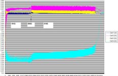
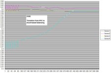
3highfinal_1_800.jpg

3highfinal_4_800.jpg

Edit...degrees F - just for you, Gregb ;)
 
Back
Top