FEMM: Modeling the 9C 2806

Kingfish

100 MW
Joined
Feb 3, 2010
Messages
4,064
Location
Redmond, WA-USA, Earth, Sol, Orion–Cygnus Arm, Mil
Greetings.

For the past few weeks and months I’ve been whittling away like a carver on a piece of wood perfecting my motor designs. At some point I realized that it was necessary to create a baseline model for comparison, hence the development of a Nine Continent 2806 hub motor in FEMM.

Disclaimer: I have zero intention of reproducing this motor other than to craft a simulation; it is just a curious engineering study and that is all :)

Basic facts:
Much borrows from Doing the Math thread, except the model has been slightly altered to fit the present MtB system.

  • Wheel = 26-inch diameter = 0.6604 m diameter = 2.0747 m circumference
    Speed = 30 mph = 48.28 kmh = 40.6 rads/s (ω) = 387.8 rpm = 6.464 rps
    Power = 2 hp = 1491.4 W (actual power measured climbing a slight grade)
    τ = P/ω => 36.72 Nm
    F = Ï„ / r => 111.2 N @ circumference
In exploring the mechanics of the 9C hub, the motor yields the following details:

  • 46 magnets / 23 poles, 51 teeth with suggested winding scheme of:
    • AaABbBbcCcaAabBbBCcCAaAabBbcCcaAaABbBCcCcaAabBbcCcC
  • Magnets are approximately 27 x 13 x 3 mm, with presumed strength is 45SH
  • Back Iron is presumed to be SST 430 x 9.5 mm thick.
  • Laminations used in the model are US Steel Type 2-S 0.018 inch thickness; however the actual thickness is closer to 0.20 mm.
  • Windings are set to 2 mm diameter 10 strands of 0.6 diameter copper, x 6 turns.
The face of the Magnet ring closest to the Stator has a radius of 99.5 mm (rounded to 100 mm for calculations). The airgap is about 0.625 mm (determined through CAD). Force required for the motor then becomes:

  • r1 x F1 = r2 x F2 => F2 = (r1 x F1) / r2
    F2 = ((0.6604/2) x 111.2) / 0.1 = 367.2 Nm
    f = 6.464 rps * 23 pole-pairs = 148.7 Hz
I have created a section model similar to how the AF motors were drawn. When I apply the properties though the resulting Force is very small, much smaller than anticipated and I am not entirely confident that I have it right. Perhaps a person kindred to modeling iron cores in FEMM can give the model a review and suggest how to correct it.

View attachment RF_Magnetics-9C-2806.zip

I would be much obliged :)
Perplexed, KF
 
Kingfish said:
Force required for the motor then becomes:

  • r1 x F1 = r2 x F2 => F2 = (r1 x F1) / r2
    F2 = ((0.6604/2) x 111.2) / 0.1 = 367.2 Nm
    Perplexed, KF


  • I'm going to look a bit further at the model, but one thing is popping out: You are probably NOT getting 367 Nm from the motor. Radius of your wheel is about 0.33m, and 367/0.33 is more than 100kgF force, is more than 1g acceleration if your total mass is 100kg, or climb a 90 deg hill (super sticky compound!)
    If your wheel is 36.7Nm, then so is your motor, if it is a direct driven hubmotor.
    With 37Nm, you should be climbing a 6.3 deg hill, or 11%.

    I noticed that only one of three coils is in place in the model, but assuming a three phase motor, two out of three coils (34) would be active at a time. How did you decide on that particular rotor angular position, trial and error?
 
Have a read though this FEMM tutorial. It will help you develop your model, so you can actually calculate torque / back emf more directly rather than relying on a linear/ radial transform.

http://www.femm.info/wiki/LRKAnalysis

Sorry for the short and not so helpful reply. I am really busy right now otherwise I would update the model for you and help you with your .lua scripting.

The tutorial is really good, you can just ignore the stuff about mathmatica or matlab analysis, using computational differentiation works well enough, you don't have to do an FFT to get the suinusoid approximation of the flux linkage waveform then differentitate wrt. time to get the BEMF

-ryan
 
Since posting I have learned that the linear model only works for certain types of machines, such as axial flux, whereas the radial flux requires the whole wheel. My bad. :oops:

Also from reading other posters, examples on the web, and even lua scripts, this particular model can be tricky, and will need to be redrawn into a simple format to reduce computation time. I’ll submit an update tomorrow.

Phyllis, I’d wager I have a units error; the value should be 36.72 Nm

Apologies; I’m still learning how to draw with crayons.
The paste here tastes great though! KF :)
 
I have an updated 9C 2806 FEMM model available now that includes the full wheel.

I have attempted to configure the A, B, and C circuits however the documentation is severely lacking on the Circuit Current format. Essentially, Circuit A is fully active at 35 Amps. Circuits B & C are phase-shifted 120° and 240°. I presume that their currents are equal to the SINE of the respective phase shifts.

Allow me to cut to the chase: 35 Amps was chosen as my working phase current; this is what the CA reports when I am chugging up a hill at 30 mph pulling roughly 2 hp. I’d like to model this in FEMM.

  • The value of Circuit A = 35, B = 120 Sin * 35, and C = 240 Sin * 35, yes?

Circuit Current format:
There is notation given in several online examples of <value X>-I*<value Y>.
I don’t understand this format and I cannot find a reference to is in the FEMM Help file. Could someone explain this to me please? :?

Under current, KF
 
I would imagine :D it is Imaginary numbers?

Is it really possible to model the motor with an AC current? because the magnets will not move, or will they?
 
Hi KF,

I recently got a caliper large enough for hub motors, so I thought I'd put it to use on my 9c that's still open. I don't know if it makes any difference for the input data or not.

1. I came up with .0186" per lamination including whatever insulator they use, so the .018" steel seems right...closer to .5mm not .2mm if it's metric input.

2. It seems like I remember reading somewhere that N42 magnets were commonly used on hubmotors. I have some N45 magnets but they're .25" so even a subjective comparison wouldn't be meaningful, other than to say they are nice and strong, much stronger than the much thicker magnets in an old X4 I have.

3. I think you overstated the air gap a bit, the only thing that I'm impressed with on the motor. I measured the ID of the rotor on mine to be 198.6mm between the magnet flats and 198.7mm at the edges. The OD of the stator stator on mine is 197.8mm , putting the gap at just over .4mm .

4. The magnet back iron is interesting with the concave shape between the spoke flanges. The jaws of my caliper aren't long enough for a good measurement, but from the best I can tell the minimum back iron thickness is only 4 or 5mm. That thickness backs almost half of the magnet, and is of course much thicker at the ends for both the spoke flanges and sufficient material thickness for the bolt holes for the cover.

Number 4 brings up a question you can help me with if running the model is easy with a change in the input. My 9C is for use as a mid drive, and I want to chock the rotor on a big lathe and cut off the spoke flanges. Not only can I save space by reducing the diameter by almost an inch, which is significant for my swingarm mounting, but by my calculations I can reduce the weight by almost 1.5lbs . The weight isn't a big issue in terms of the bike weight, but at the perimeter of the motor that will spin at over 1krpms it would be a great place to shed that kind of weight.

The bolt holes prevent me from taking off too much material, but my question is this. Does just a change in the backing iron from 9.5mm to 5mm show a performance change in the model?

Thanks,

John
 
Hi Bearing

Magnets move with the rotor in the 9C model, and the stator is fixed.

Here’s the link to the FEMM example with the odd Circuit expression:
http://www.femm.info/examples/lrk40/lrk.fem

Below is a comparison of the properties in the FEMM application, compared to the FEM File formatting, following this convention where

  • App Circuit Props; FEM File properties
  • Circuit A = I*4.25; <TotalAmps_re> = 0, <TotalAmps_im> = 4.25
  • Circuit B = -3.680607966083864-I*2.125; <TotalAmps_re> = -3.6806079660838642, <TotalAmps_im> = -2.125
  • Circuit C = 3.680607966083864-I*2.125; <TotalAmps_re> = 3.6806079660838642, <TotalAmps_im> = -2.125
The model appears useful but I’m a like a fish outta water trying to understand it. :? Do I need to worry about imaginary currents? Are the values in the 9C model workable? What do I need to change to get the model to work properly?

Many thanks, KF
 
John in CR said:
4. The magnet back iron is interesting with the concave shape between the spoke flanges. The jaws of my caliper aren't long enough for a good measurement, but from the best I can tell the minimum back iron thickness is only 4 or 5mm. That thickness backs almost half of the magnet, and is of course much thicker at the ends for both the spoke flanges and sufficient material thickness for the bolt holes for the cover.
Hmm...I'm curious about this; AFAICT, the magnet back iron is not the part with the spoke flanges, but rather just a thin layer between that part and the magnets themselves. The spoke flanges and the ring they're a part of is aluminum, on both of the 9C rings I have (one silver one black), both from the 280x series. So the back iron is actually almost to the outside of the threaded screwholes (they actually are drilled into both the back iron and the aluminum outer ring). I don't have a caliper; the smallest-division ruler I have is a stainless steel 64ths/inch, measuring ~13/64ths, which comes out close enough to 5mm when I convert it.

It's possible your 9C is not made like mine; I suppose there are different generations and versions; yours could be all-steel for the ring/flanges.

The bolt holes prevent me from taking off too much material, but my question is this. Does just a change in the backing iron from 9.5mm to 5mm show a performance change in the model?
If I'm correct, or at least, if your 9C is like my 9Cs, you could remove the spoke flanges without affecting the back iron, however the bolt holes being partly in the aluminum and partly in the iron may mean less tension on the bolts when the aluminum is removed.

Also, it won't shave off as much weight as your estimate, probably, if it is aluminum flanges.
 
I just checked with a magnet and everything but the magnets and paint is steel/iron. The spoke flanges are pretty thick compared to steel bike hubs, and about the same thickness as AL hubs, but it's fairly soft iron compared based on making my alignment marks for the covers. Based on that softness, SS is doubtful, unless there's a soft SS. I haven't notices rust on any rotor, so I'm perplexed about the actual ferrous material used.
 
Kingfish said:
The model appears useful but I’m a like a fish outta water trying to understand it. :? Do I need to worry about imaginary currents? Are the values in the 9C model workable? What do I need to change to get the model to work properly?

Many thanks, KF

You are right about using the sin(angle) to determine the current in the phase. But you have to make sure that your Phase A (assuming that is the phase that starts at 0 degrees) is actually at a zero-crossing of the voltage (i.e a maximum point of the Flux Linkage).

I took the liberty of updating your model so that it will work, and attached the script to get torque as you rotate the rotor.

Here is what I did to the model.

1) I moved it to so that the center was at 0,0 so that the torque calculations work. To figure out how far to move it, I selected the 2 arcs that form the center hole, and then click the "scale" button, it automatically selects the center of the points selected as the default base point (I usually copy and paste those values into a text document then paste them back into FEMM after I select all the geometry and click the "Move" button, but in this case I suspect you actually drew your design in FEMM because the center was at 122 , 122 I think) . That scale to find the center trick comes in handy when you import a DXF and it puts the center at some randomish point

2) I made all the components of the rotor part of group 2 (I use the group tool, and circle select to select everything starting from 0,0, make it all group 2, then I do the same thing again but only drag the circle select out to the airgap between the stator and the rotor so that only the stator is selected then make that group 1 again)

3) I added air around the outside of the stator and put a boundry conditino on the outside of that. That way you can see what happens if you make your rotor back iron too thin. I made the center air aswell for the same reason as adding air around the outside

4) I made your blocks to "let triangle choose block size" because your meshing value of 1 was way too slow at solving and doesn't provide much more accurate information. As a rule, I always let the triangle choose block size, and if I find I want tigheter meshing in a particular spot, I will redifine a block around the part I really want to know the details, it is much .... much faster and provides the same results. (I was lazy and didn't take the time to do all the copper sections , but it is still much faster and good enough .. I'll let you fix the copper blocks). I also updated your stator to use M19 laminations rather than solid iron, it makes a small difference to the saturation point of the stator.

5) Set the problem frequency to 0 (the frequency has to be done manually along with the rotation of the rotor in the lua script), and set the currents in the circuits all to 0 aswell.

After that I ran my script to rotate the rotor 1/2 an electrical cycle counter clockwise to see how the EMF looked. It appers as though if you want to drive this as a motor counter clockwise (from the position that your rotor is in right now), you want your phases to sart off at
A=-180
B=-60
C=60

Because of the crazy tooth / pole combination it makes it hard to visually determine if the rotor is at the maximum flux linkage position for phase A, but from my quick simulation it seems good enough to use those as your torques. I made my simulation take larger steps because of the tight meshing makes things slow and I didn't want to wait an hour for the result so I am not that confident that the phase angles of A is exactly -180, from the visualy inspection I suspect it is actuall more like -190 degrees (i.e the rotor is a couple degrees counter clockwise past the maximum flux linkage position of phase A)

Anyways, from this simulation I suspect the Kv of the motor to be 17.1 RPM/V in Delta, or 9.84in Wye. Those seem low to me, so there might be some parameters wrong in the model. What is the real Kv of this motor?

I attached a .zip with the modified .FEM file and the 3 lua scripts I updated to work on the model. New flux goes thorugh and gets flux linkage as you rotate the rotor at no-load, so you can paste that into a spreadsheet and do back emf calculations and stuff. Running Torque is pretty much the same thing as new-flux but you set the RMS phase current you want (in Delta) and it extracts the torque as it goes through the rotation of the rotor, you can take screen shots of that (use the mo_savebitmap command I think) to see what happens to the flux density in the teeth as you increase the current. Variable torque lets you quickly figure out how current in the coils affects the torque. The settings I have in there show that even as you push 100A RMS per phase through this thing (100NM of torque) the Kt is still pretty linear wich is a good sign that the magnetic design can handle that much toruqe, To figure out if the electrical circuit can handle that much heat is the bigger question.

have fun with that.


The next things to do to improve your model woudl be to make the stator teeth body section uniform thickness rather than the stator slots uniform width. The way it is right now, the bottom of the slots pinch the flux in the tooth. Also the thickness of the tooth heads looks a little thin to me, but I haven't looked at a 9C stator so maybe that is how they are made.

-ryan

*Edit changed the sign on the C phase angle so that it was correct, and removed the text about how to tell if the rotor is in maximum flux becase it doesn't apply to this crazy pole/slot combination.
 

Attachments

  • RF_Magnetics-9C-2806-biff.zip
    22.9 KB · Views: 96
Hi Kingfish,

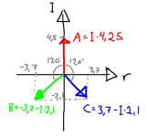
I made this picture to try to explain the complex currents. The theory behind this is to make the windings 120° out of phase from each other.
phaseCurrents.PNG
If we call the angle x, the current i, then we have the following equation:
A=i*(cos(x)+I*sin(x))
B=i*(cos(x+120°)+I*sin(x+120°))
C=i*(cos(x-120°)+I*sin(x-120°))

And in the specific LRK case, where x=90° and i=4.25A we have:
A=4.25*(cos(90°)+I*sin(90°))=4.25*(0+I*1)=I*4.5
B=4.25*(cos(210°)+I*sin(210°))=4.25*(-SQRT(3)/2-I*½)=-3.7-I*2.1
C=4.25*(cos(-30°)+I*sin(-30°))=4.25*(SQRT(3)/2-I*½)=3.7-I*2.1

So, as the angle x increases, the vectors A, B and C will rotate in a circle.

I have been playing around a little with FEMM, and AFAIK there isn't a way to simulate AC-currents (which will induce eddy current losses and similar) and at the same time have the magnets rotate. You can only simulate static magnet positions, with DC or AC currents. But i may be wrong, and if there is a way to do that, it would be great.
 
John in CR said:
I just checked with a magnet and everything but the magnets and paint is steel/iron.
Ok, then it is definitely different from mine. Not too surprising; I'm sure they revise stuff all the time.
 
Hi Biff

Thanks for the update and hugely-helping hand! I was about to post my new model & report last night, so let me comment on yours and then I’ll rewrite mine using yours as a base. :D

  • The next version that I was going to upload has the model re-centered by -122, -122 (you nailed it).
  • I had fixed the slot teeth to have chamfered corners which greatly helps the modeling but didn’t add a lot to computation.
  • Alignment of teeth and poles: I crafted these separately; the teeth begin/end at TDC 90° however the poles were dropped in beginning at 100° - and I forget why (my bad).
- That said –

  • I spent the evening revising the DXF and learning how to fix my model in FEMM as well, and I did have a major update to post – however, I took your revisions, deleted the model and re-imported the corrected model.
  • I updated the magnets to align with the teeth at TDC 90°, changed the mesh on the windings to default per your suggestion, revised the slots back to the actual geometry, and the back iron was changed to 6 mm thick – which is as close as I could measure on my units. Also – the boundary circle for the air was updated to the size of a 26” wheel for perspective.
Previously the scripts ran fine with your original model. However I have them pointed to the V2 and now I am getting errors. The Group 2 iron and magnets are rotating, however the property nodes are not with any script. Also I think the full-radius slots add too much time; I may simplify this but not to the degree of the chamfers.

Any idea why the nodes would not rotate? :?

Especially thankful, KF :D
 
Hi Bearing

Thank you for taking a moment to explain the trig; I see it now and greatly appreciate the explanation :D
I did note that rendering the B vectors helped visualize those imaginary forces; lots of fun and learning a lot!

Best, KF
 
CA measures battery current, phase current is generally greater. According to Jusin's measurements, max phase current on a 7 turn 9C is about 60 amps and torque about 70 newton meters, if I remember correctly. Much beyond that something starts to saturate and efficiency drops. It is in a thread here on ES.
 
Hi Alan

Understood, and appreciated! :)

Then my presumption of the CA MaxA = 35 Amps is really measuring battery current, yes? And if so, then we need to change this to 35 * √3 to get ≈ 60.62 Amps for Circuit A @ 0 SIN, yes?

Hopeful, KF
 
Luke or Justin are the ones to ask about stator saturation. I recall Luke saying that 90A was the saturation number, but I don't remember any clarity about whether that was battery current or phase current, though at full duty wouldn't they be the same?
 
Justin's testing was without controller, so it was phase current.

Our controllers run the phase current through two coils in series at one time. The third coil has no current.

Even at wide open throttle the PWM will be active if any current limiting is going on. Not common to have no PWM occurring, generally only happens near max speed.

Phase current is 1/pwm duty cycle times battery current.
 
Kingfish said:
Hi Biff

Any idea why the nodes would not rotate? :?

Especially thankful, KF :D

The nodes have to be in the group as well as the block label. It doesn't matter what group the lines / arcs are in, but I like to put them in the group aswell, so when you select the group in the simulation editor (click on group selector tool, and right click near one of the blocks in your group) everything you want to rotate turns red.

Post your new model and I'll have a look

-ryan
 
Thanks Biff :)

Here ye be... sans scripts (only the file name was changed in the scripts)

Much appreciated, KF
 

Attachments

  • RF_Magnetics-9C-2806-biff-V2.zip
    19.5 KB · Views: 64
Epiphany! :idea:
OK now I get it! I changed the arcs and lines to Group 2 and re-ran the scripts; it chugs along very quickly without errors.

Amazing; thank you :mrgreen:
~KF
 

Attachments

  • RF_Magnetics-9C-2806-biff-V2-fixed.zip
    19.5 KB · Views: 80
New Model looks good.

here are some comments:
1) You could keep the slots with square bottoms and tops, it makes simulation faster
2) The slots are still fixed width which causes a taper in the tooth body pinching the flux at the base althought less so because of the round slot bottoms. I doubt that is how the NC motor is really built, typically a motors tooth is fixed width and have tapered slots.
3) with the magnets in their current position your phases are about 28degrees behind of phase A lying on the x axis, i.e the phases are A= 152 degrees, B = -88 degrees C = 32. Either change my torque scripts to use those angles to get the right toruqe, or move the rotor about 1.22 degrees (clockwise). If you use my running torque script without changing the angles, you will see that the torque will vary quite a bit during a cycle. Once you correct for the phase change, the torque will be more constant, but will still vary as the poles move past lowest reluctance points.

-ryan
 
Back
Top