FOC questions

Mihai_F

100 W
Joined
Oct 11, 2021
Messages
128
hello to all,
I have studied FOC motor control for a good while now, i understanded most of it. If i remember well you have done you own FOC code, so i have some questions about FOC algorithms to clear things out.
So far i understand and made (code) the following: clark transform from Ia, Ib, Ic to alpha and beta, then park transform to d and q, here are 2 formulas one for d aligned with alpha and one for q aligned with alpha, i used q aligned with alpha in order to have a positive q (the other one gives a negative q), then a simple command for d and q no PID yet, then inverse park to get alpha and beta from commanded d and q, then find the theta angle and modulation index from alpha and beta, then from here i used some code i found on github for SVPWM dutycycles, wich i kinda get what it does but not completely.
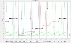
So basically i run this code in STM32F401(black pill) to simulate FOC and i produce artificially 3 sines 120 deg apart, at ~1Hz, and watch all computed FOC variables on var viewer of stm studio, i can change the q and that changes the SVPWM, plus i give feedback to my artificial sines to be more real situation/simulation.
The question are:
1. The theta angle (rotor angle) calculated from atan2(beta, alpha), can be used in sensorless/encoderless FOC algoritm, will it work?, is that the right way of doing FOC?
2. Why is SVPWM out of phase 180deg from initial input sines U V W, in the screenshot?, i do not think that is right...
3. I will use hall sensors only for startup, should i use them to find the theta angle and sector from them after startup on the runn?
4. I plan to use STM32F407ZG (168Mhz) and 3 hall current sensors on phases, and have Tim1 channel 1,2,3 center aligned complemetary pwm generation (mode1) and channel 4 output compare to trigger ADC in the center of the PWM pulse, ADC1 injected ch1, ch2 and ch3 sequential order , is this the "correct/good" way to do things?
5. If i understand well, if ARR is 1000 and q comand is 0 then all 3 duty clycles are at 500, all fets swithcing all outputs fom high to low (comlementary PWM half on, half off of the time), in that case the motor is i brake condition (shorting the phases together), how to achieve motor coasting and not braking when q comand is 0, like when you go down hill with throttle at 0 , coasting and not braking.
here are the screen shots:
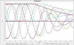
FOC SWPWM 1.jpg
FOC SWPWM theta and sector.jpg

Code:
//FOC simulation

volatile int PermuataionMatrix[6][3] =
{
    { 1, 2, 0 },
    { 3, 1, 0 },
    { 0, 1, 2 },
    { 0, 3, 1 },
    { 2, 0, 1 },
    { 1, 0, 3 }
};

volatile int UDC=1000;

            // generate step for sine
            sin_step = sin_step + 0.001;
            if(sin_step >(2*M_PI)) sin_step = 0.0;

            //dutycyle= sin(sin_step);

            //Generate 3 sine waves 120deg apart
            dutycyle_U= sin(sin_step)*1000*amplitude_comand;
            dutycyle_V= sin(sin_step-(2*M_PI)/3)*1000*amplitude_comand;
            dutycyle_W= sin(sin_step+(2*M_PI)/3)*1000*amplitude_comand;

            //Clark transform
            //alpha= (2.0f/3.0f)*dutycyle_U - (1.0f/3.0f)*(dutycyle_V - dutycyle_W);
            alpha= 0.666666*(dutycyle_U - 0.5*dutycyle_V - 0.5*dutycyle_W);
            //beta= (2.0f/sqrt(3))*(dutycyle_V - dutycyle_W);
            beta= 0.666666*(0.866025*dutycyle_V - 0.866025*dutycyle_W);
            

            //find theta angle
            theta= atan2f(beta,alpha);

            //Park transform q axis aligned to alpha
            d_axis= alpha*sin(theta)- beta*cos(theta);
            q_axis= alpha*cos(theta)+ beta*sin(theta);

            //Command
            amplitude_comand= FilteredReadADC12bit/4095;    //get amplitude
            d_axis_new= d_axis;
            q_axis_new= q_axis* amplitude_comand;    // amplitude
            

            //Inverse Park transform
            V_alpha= -d_axis_new*sin(theta)+ q_axis_new*cos(theta);
            V_beta= d_axis_new*cos(theta)+ q_axis_new*sin(theta);

            //find new theta angle offset by 90deg and modulation index
            theta_sh= atan2f(V_beta,V_alpha)+M_PI;
            mod_index= hypotf(V_beta,V_alpha);

            //Calculate duty cycles code from github

                //Max_mod_ix= UDC * (1.0f/sqrtf(3.0f));
                Max_mod_ix= UDC * 0.577;

                if(mod_index > Max_mod_ix) mod_index = Max_mod_ix;
                Scaled_mod_ix= mod_index / Max_mod_ix;

                Sector= theta_sh * (1/(M_PI/3));
                angle= theta_sh - (M_PI/3) * Sector;

                T1= Scaled_mod_ix*(sin(M_PI/3- angle));
                T2= Scaled_mod_ix*(sin(angle));

                Ti[0] = (1 - T1 - T2)*0.5;
                Ti[1] = T1 + T2 + Ti[0];
                Ti[2] = T2 + Ti[0];
                Ti[3] = T1 + Ti[0];

                CCRA = 1000 * Ti[PermuataionMatrix[Sector][0]];
                CCRB = 1000 * Ti[PermuataionMatrix[Sector][1]];
                CCRC = 1000 * Ti[PermuataionMatrix[Sector][2]];
 
rotor angle is not tan inverse of beta, alpha. For closed loop, it either has to be estimated by hall sensor interpolation or sensorless algorithm.

recommended to do simultaneous ADC current channels using multiple ADC instances, seems the one you mentioned have 3 ADC instances
 
Copying in my answer from the private chat you started:

1) You can't use directly the atan2(alpha, beta) because there's no feedback mechanism. It's unstable. You need to include in some way or another information from the sensors. You will also find that atan2 on a voltage command directly injects system noise into the angle which will make it unlikely to work. You have options of flux integration and phase locked loop/kalman filter to stabilize your system.
2) I think your definitions are wrong. You're saying q aligned with alpha and d aligned with alpha but this makes no sense. DQ is rotating. It can't be aligned with either. I'm not really sure what you're meaning here.
Bear in mind atan2(a,b) is out of phase with atan2(b,a).
3) you can use hall sensors for startup, for full range of speed or not atall. All are options.
4) your way is quite sensible but you can use ADC 1 2 and 3 to get simultaneous results. With that MCU i recommend using pc10 11 and 12 to do current measurements, pc13 for bus voltage and pa1,2,3 to do phase voltage measurements. This will make your system easily compatible with both VESC and my firmware.
5) motor coasting is achieved by turning off all 6 MOSFETs at the same time. There's specific code for the stm32 to do this. Look at my GitHub for generate break and generate enable commands. I took them from there ST bldc library but it's quite hard to find them.

Further, using svpwm isn't critical, you can just implement inverse Park and Clark matrices. It's much more intuitive and creates an identical result at the expense of a very small instruction count increase.

Lastly, 1.0 should be 1.0f otherwise you will end up with double promotion... That is, the compiler will interprete 1.0 as a 64 bit number which there is no hardware accelerator for, so single instructions become hundreds of instructions.
 
My advice is progress in the following order:
1) get ADC measurements synchronous with center aligned pwm at about 20khz and verify by pin toggling that you're getting one interrupt from the ADC per pwm cycle.
2) implement the tri state functions, break and enable and test them. Implement a function that immediately tri states the bridge in the event of over voltage and over current. Test it by injecting a suitable voltage to the ADC inputs. Do not progress to using a motor until you have done this.

3) define an angle to use. Do not worry where the angle comes from for now. Implement fast sin and cos algorithms.
4) implement Clark and Park transforms to get current in alpha beta and dq reference frame
5) implement inverse Park and Clark transforms to convert Vd and Vq into Valpha V beta and then to UVW
6) shift the signal to the middle of ARR and write to the timer registers.

At this point you'll be able to test the functions by defining a small Vd and in a function outside the ADC interrupt incrementing the angle slowly. You'll be able to watch the id and iq and see if they are broadly stable as the motor rotates

With this done, the remaining work is
1) implement the feedback from current id iq to vd vq via PID loop MESC_Firmware/MESC_Common/Src/MESCfoc.c at 35e3e044b21ba9684972a7ec72e37ac9cfa1d26d · davidmolony/MESC_Firmware
2) truncate the vd and vq so it never exceeds timer arr or 0
3) generate the angle, via encoder, hall sensor interpolation or sensorless observer. MESC_Firmware/MESC_Common/Src/MESCfoc.c at 35e3e044b21ba9684972a7ec72e37ac9cfa1d26d · davidmolony/MESC_Firmware

For these parts, I recommend you simply go to my code base and copy/adapt the functions.
 
Last edited:
Hy,
Thank's for guidance, i'm back with some progress, i managed to spin the motor in a crude "open loop"/ no feedback mode, i'm doing this on a test controller with a small 1Kw motor, and off the bat i have to say that i'm blown by the fact that this space vector control mode (not FOC yet) can spin the motor at 3 to 5 RPM with no noise and smooth rotation, as compared to bldc mode where the torque ripple vibration and noise is off the roof at that low rpm. Then soon enough i realized the importance of the fast math (stay with float to use FPU) in the computing loop (ADC triggered), in order to have all the FOC computations done on each pwm cycle, i also realized the importance of fast_atan2 and sin_cos_fast with LUT, having studied MESC firmware in the last 4 days, cool and good stuff there. I also realized that this FOC application needs a CPU that has a decent ++100 Mhz frequency, black pill F401 at 84Mhz is at the low end( and has only one ADC) , but il upgrade to F407 168Mhz or F446 180 Mhz, witch will do just fine. Now i have to understand the flux observer, in order to have the theta angle. Can you please give a brief description of what flux observer has to calculate/its idea, i observed that it takes inputs Ld, Ldq, Rm, La, Lb, Va, Vb, Ia, Ib, but i'm having a hard time wrapping my mind around what it does. I mean Clark, Park, and inverse of these transforms, i read the theory and watched tons of tutorials, but i understanded them mostly when i simulated them and played with they inputs and watch all that in var viewer, i plan to do the same with flux observer also.

I documented most of it in these github pages. Unlike most appnotes, my intention with this was to make it as easy as possible for someone to replicate my work from scratch. There's no intent to over complicate or maintain some secret sauce and non of the intellectual masturbation you get in technical papers. It's as simple as i could make a very complicated topic. Bit of a work in progress but the sensorless observer is covered.

Probably also worth noting that a fair few things have changed since i wrote it. It all stands as being correct (with a few typos) but the interrupt setup has changed for example and the field weakening uses a non linear ramp (since it is an inherently non linear process).
 
Last edited:
I have some questions, regarding mesc firmware:
1. i understanded that the phase voltages are "processed" only in tracking mode when the H bridges are disabled, and flux observer is "processed" at each pwm cycle, inside the calculations of flux observer is needed the phase voltages to calculate the FOC Angle, so my question is how is FOC Angle computed in each pwm cycle in run mode without phase voltages if they are "processed" only in tracking mode ? (if we consider full sensorless mode, no halls)
2. i understand that ADC1,2,3 is configured to trigger in the middle of pmw period, currents Iu,v,w read at once by ADC1,2,3 rank1, phase voltages Vph u,v,w read at once by ADC1,2,3 rank2, and the rest of converions Vbus, thr, temp... ect., that means that phase voltages are = to Vbus if the H bridges are enabled, so the phase voltages are actualy = to the phase voltage (BEMF) onlt if H briges are disabled. is that right? so how do i read phase voltages in run mode to have the for fluxobserver calculation?
3. in tim1 IRQ is triggered at top and bottom count, and that handles writepwm, why is need to update the pwm registers at top and bottom count, if adc values and all the foc math is done only once per pwm cycle (by the ADC IRQ witch calls fast loop witch calls all the rest) ?


1) The Observer runs during run and tracking mode. As you point out, during run the phase voltage is useless, either Vbus or zero so we ignore it and use the pwm value. During tracking, there is no pwm but the measured voltage is now available so we use that. The observer actually runs in alpha beta frame not uvw frame, that is on the other side of the Clark transform.

2) see 1

3) the timer interrupt is at top and bottom because you can update center aligned pwm 2x per period... There is a power pulse to the motor on the rising AND falling edge. MESC only runs the FOC loop once per pwm period, to account for hardware with low side shunts, but interpolates the angle between FOC loops to get higher position resolution. This helps with efficiency and high speeds.
 
hy,
i got success spinning the motor in sensorless FOC using the flux observer algorithm (although manually started :D ) and no PI yet, just manually playing with Iq and Id inputs, that is so cool though, seeing their effect.
i still have some questions regarding flux observer:
1. in the comments of you code you say :
"// Unpuc the observer kludge
// The observer gets into a bit of a state if it gets close to
// flux linked = 0 for both accumulators, the angle rapidly changes
// as it oscillates around zero. Solution... just kludge it back out.
// This only happens at stationary when it is useless anyway."
some code then (actions taken)
"//This was altered because otherwise basing the flux on the observed flux
//causes issues a step change in direction, so at low speed - e.g. during hall sensor startup - it causes instability."
i really do not understand what is that about, can you please explain its purpose?
2. what is the purpose of "CLAMPED_OBSERVER_CENTERING" ?
3. why this way: "flux_a = flux_a + (Vab.a - m.R * Iab.a)* pwm_period- m.L_D * (Iab.a - Ia_last)" pseudocode from mesc
instead of this way "flux_a = (Vab.a - m.R * Iab.a)* pwm_period- L_D * (Iab.a - Ia_last)" pseudocode
why "adding"(kind of) to itself?
excuse my uncultured ignorance :D this is a new world to me, the learning curve is strong, but i'm getting there.
"4". next topic is HFI, do you have any references from where you learned about implementing it, i mean i "googled" and "whatched", but something like your explanation that you have for control loops, eg what is HFI D and HFI 45?
The kludge is for very low speed. The observer works by recognizing va and ia and vb and ib are sinusoidal. However at low speeds, with current feedback, the sin waves will drift randomly, and then they no longer work with atan. They can either drift away from being centered around zero, hence we clamp them at the max flux linkage, or they can get stuck exactly at zero in which case noise can "rotate" the observer very very fast.

Why added to itself? Well that's integration. Integrating a voltage gives a flux linkage. Integrating a sinusoidal voltage gives a sinusoidal flux linkage. The beauty of the flux linkage observer is that it has no lag because integrating sin and cos gives a constant 90 degree offset.

There's no hfi documentation. It came out of a discord discussion between me Elwin and Benjamin Vedder,a lot of hacking and testing and screeching motors for a few days. Use hfi45 if you do but your best option is definitely to use sensors. Use the MESC observer preloading option.

Basically hfi45 injects a signal in d and q on equal proportion and watches for a current response, which should have a magnitude given by the inductance and voltage applied. You advance the phase using a pll/integrator fed with the error from the inductance measurement.

If you get RL and flux linkage right you probably won't need startup routines like hfi, it should just spin up from zero with a prop.
 
Last edited:
hy,
I had an ideea with regard to flux observer, it started when i questioned the "add to itself" - integration
"flux_a = flux_a + (Vab.a - m.R * Iab.a)* pwm_period- m.L_D * (Iab.a - Ia_last)" pseudocode from mesc
The integral integrates, and if there are steady states or very small changes in the Vab amplitude it starts to "wind up" and that needs clamping (plus other reasons), as i observed. This made tracking of the angle a low speed a bit difficult and it would not start if, not enough Vab amplitude to stop the windup of the integral.
And that made me think what if i remove the "add to itself" - integration and do this
"flux_a = (Vab.a - m.R * Iab.a)* pwm_period- m.L_D * (Iab.a - Ia_last)" pseudocode. It would not wind up any more. So without clamping and without de-kludge, just the two equations for flux a and b. Having the fluxes go to 0 at no speed caused the observer to "rotare" because of noise (as you said), this kind of helped when starting motor because it gives it a small shake, witch in return gives back enough Vab amplitude (and current) to calculate angle. All this produced the needed angle even at very low speed, i could give a bit of q command, the rotor would shake slowly CW to CCW a bit, and if i just slowly rotate/help it to one direction it would start right away, the torque is good, d stays at 0 throughout full range of speed, if i increase the d it would do field weakening just fine, it gets the angle just fine. I tried it with 2 different motors one small high speed motor 10krpm (12pole 22mm 50w) and one big low speed high torque 1Krpm (32pole 130mm 1kw), they could start easy and run fine, the RL must be tuned a bit though. To be noted i have hall inductive sensors on all 3 phases.
Now this is baffling me, why so?, i mean it is clear that your flux observer works, no doubt about that, but why this simplified version works to, and why at low speed from stand still " works better" ? or at least it appears to do that. That shaking at start up is certainly not desired, but with HFY or a simple start algorithm to slowly rotate the angle open loop 2 sectors to get the angle and then switch to flux observer and closed loop.
Next question is, is the angle from integrated version different (as in radians) from the non integrated version?
Any thoughts? Just exploring...
This is very interesting. I'll try it. My best guess is that your system is locking onto the inductance difference between ld and lq or something like that. I never tried this before since my observation has always been that the voltage is quite noisy so taking an atan2 of them would be noisy also.

You can construct the "observer" directly as you said, taking advantage of atan but the angle would be shifted 90 degrees (due to the lack of integration).

Worth noting is that if you don't have the integration, it is strictly not a flux observer... But that's being pedantic...
 
Last edited:
Hy i'm back with more progress, i'v been testing on 3 different motors and speeds, testing sensorless staring and running algorithms. (i did not wand to just copy the mesc code, i preferred to just learn from it).
So, at 0 throttle when motor in breaking, if i rotate the rotor (even slowly) I noticed the flux observer will "read" the rotor angle, because turning the rotor will generate voltage but because coils are shorted (0 throttle = breaking) that will draw current, enough of it for the flux observer to get the angle, so that made me think, how to get that current at 0 throttle without rotating the rotor? well inject a small voltage in to d axis and rotate it, that produced the needed current for the flux observer, and when throttle increased d axis voltage will stop and q axis voltage will begin, flux observer being "primed" with current already, now gets the needed voltage from duty cycle and then it "reads" the angle. This method starts the motor from stand still every time, i managed to start motors with propeller as loads, they work well.
The starting torque is weak, with big load (holding it with a hand, lightly) the rotor will oscilate back and forth until enough q axis voltage is given to overcome the load. This oscillation is because the angle is switching from up counting to down counting and back. This brings me to my next problem. This starting method has an angle "ambiguity" it does not all ways start in the same (commanded) direction.
Once started at slow speed (small enough q voltage) if i apply big enough load to stop the rotor, it will switch direction if let go, or oscillate back and forth if i hold on to it.
The q command does not go thru PI, only the d command. Running q thru PI behaves like constant speed mode, ie, if i load the motor it tries to hold the speed and increases q , still to figure that out why it does not work as i expect it to... . Right now q is tied to potentiometer after adc filtering, witch runs it simple.
Other things i'm still studding the HFY, i'm having a hard time understanding its implementation in the mesc code, any explanation will be greatly appreciated.
What do you think about that angle ambiguity. how about my starting method
I think you've hit one of the issues with a direct voltage arctan observer, there's angle ambiguity. The same voltage generated regardless of which way you spin... This doesn't happen with flux linkage.

HFI. You inject a positive and then equal negative voltage in dq immediately after ADC measurement, at top or bottom of the pwm cycle. You're then looking for change in idq current. We know current changes more with lower inductance so based on which phase has the biggest current changes you can see the d axis.

There's a lot of variants of this. MESC runs a crap pll based on whether the total current is higher or lower than a predetermined threshold, set at half way between d and q.
 
The simplest way to startup nicely is to use flux linkage observer and preload it with openloop values varying sinusoidally with time. If you keep running the actual observer inn the background, then at some point just stop preloading and it's already in closed loop.
 
Hy i'm back with progress,
Big update, i transformed the code to a more readable and maintainable way, with structs, pointers and all that stuff (like mesc).
I decided to do it now while it is "simple" and not "many" lines of code, because later would be much harder to do it...
I kept playing with the flux observer (the original one with integration) managed to get it work ok, but one thing that bothered me was its integration windup when there are steady stats in flux. So i thought to myself how to integrate / keep track of the past values without windup. Well a low pass filter will do that, but a certain kind of LPF that changes its integration based on the change in values in order not to have lag at all. I used in the past this type of filter with grate success, it is fast and adapts fast, so i tried it:
//Low pass filter for Flux observer
_motor->flux_a_filt += (_motor->flux_a - _motor->flux_a_filt) *(fabsf((_motor->flux_a - _motor->flux_a_filt))*0.001f);
And the result was fantastic, i got really smooth motor operation, it keeps the rotor angle if i stop the motor by hand for short period, and the best part is at start up and at really slow speed, it just works spot on, as soon as it has the smallest amounts of flux it gets the angle, and goes.
Best part out of this, i managed to run my big 20kw motor (one from plane) on this foc algoritm, first time running it on foc (without load), mind blown. I also tryed another motor, 2kw 4000rpm, on this foc, good results so far.
All sensorless so far. I refuse to work with position sensors any more, due to a LOT!!! of problems (all kinds) with them in the past.
Next, i can try some loads , but only +/-60 phase amps so far on this hardware (current sensors limit).
 
Hy guys, I have some questios regarding FOC operating modes, speed, duty, torque. So far in my implementation PID controlled the Vd comand in order to keep Id at 0. Vq directly controlled by throttle input gives duty mode. I tried Vq thru PID and it worked like torque mode, throttle input dictates how much Vq is needed and generates torque, if no load motor reaches max speed even at 10% throttle input, if i apply load it slows down (for same 10% thr input). But i have a hard time understanding how to do speed mode (constant speed), i guess you would have to know the max possible speed and corelate that with thr input.
Can you explain pleas a bit how these modes are implemented, i studied MESC code quite a bit now, but i'm having a hard time following thru it.
How about regen in different modes?, i noticed in my so called "duty" mode the motor opposes turning faster than commanded by the throttle, or when motor is stopped it opposes turning, and noticed the Vbus rises if i force the motor to turn fast.
What modes would be used for terrestrial use?
I have intend to use the FOC controller on terrestrial projects, i'l make a post on them soon.
I recently had the pleasure to ride a talaria sting, i tried to figure in what modes (toque/speed/duty) it works... it had regen when going downhill, but when going straight or up, it would seen duty or speed, or else ......
Any way some explanations with practical examples regarding FOC operating modes it will be greatly appreciated.
Terrestrial or ground based vehicles always want torque mode. Some people run balancing vehicles with position, duty or speed but I don't think this is right.

For duty mode, you might choose to buffer the throttle request and only let it decrease the duty if the iq being regenerated is low to avoid the aggressive braking.

For speed control most people typically have a second PID controller that increased and decreases the torque request to maintain a speed. This is a bit tricky to tune, it's very dependent on the inertia and damping/drag.

You can construct a PID control loop to have a power, position, duty, speed... Pretty much anything where the input is the throttle and the measured speed duty position... And the output is a torque request.

Maybe people run duty as a proxy for speed since it's much simpler.
 
Back
Top