GaN and IMS MESC controller boards

mxlemming

100 kW
Joined
Jul 17, 2020
Messages
1,122
So I want to share some new controllers I have been working on. I am umming and erring about opening the source, since basically no one built my last controller, which works great... If you actually want to build one, perhaps PM me for gerbers.

If you want to DIY a controller, try the MP2/CCC ESC.

This is in some way, a continuation of the original MESC board I made, see:
https://endless-sphere.com/forums/viewtopic.php?f=30&t=107672

GaN board
This board is based on EPC2302 MOSFET, which are probably the best GaN 100V MOS available right now. I am not totally sure of that, but I think so.
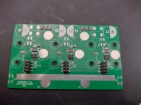
They are 5V gate drive, and have incredibly fast switching characteristics, sub 10ns. This presents problems, they simply cannot be used like traditional ES through hole controllers. They have to be laid out absolutely meticulously, with <<1nH inductance in the switching loop (TO-220 has about 7nH, TOLL has about 1nH before considering PCB inductance). The layout below seeks this extreme inductance minimisation, bear in mind there are also uninterrupted power and ground planes on the two inner layers.
MESC GaN layout.png

The gate drive lines also have to be incredibly low inductance to cope with the high switching speed. I chose to route with differential pairs, using the same board as I use for the IMS. Generally, the appnotes recommend that you place the gate driver right next to the MOS, and minimise the gate inductance to extreme levels... I had a hunch this was not necessary. Calculation of the approximate inductance, capacitance and resistance (4.7 ohm) of the gate/trace showed the damping factor to be high and the resonant frequency away from the switching speeds.
2EDF7275 layout.png
MESC GaN Layout top.png
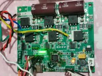
The gate driver needs to be slightly special, work with 5V gate drive and have extreme switching speeds and matching. I used 2EDF7275F for this, an isolated SOIC16 part with low tens of nanosecond delay and matching, and high drive ability. This is not explicitly a GaN driver, is 5x the size of intentional GaN drivers and it is not mentioned atall in the datasheet, instead referring to logic level MOS. Again, I had a hunch this was OK, and wanted to use the same drive board for my IMS power stage.


Obviously (or perhaps not?) you cannot run a GaN stage with low side current sensing, so I added a hall effect phase current sensor, a Chinese copy of the Allegro ACS71x, for 20A and shunted them with a 1mohm resistor to increase the range. I highly recommend not buying these Chinese copies, the noise floor is huge, about 1A on a 20A sensor, but Allegro have decided not to sell to us for now, so what you gonna do...
View attachment 1

Building it was surprisingly easy. I was fully prepared for an absolute battle with the cursed footprint, but a bit of flux, paste (manually applied with a scalpel) and hot air and they just floated into place, with lovely clear solder bumps on the wettable flank. Crazy easy compared to my expectation.
GaN solder bumps.jpgGaN soldered.jpg
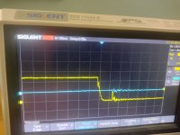
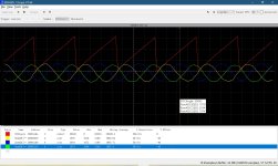
I ran it up to 40A (that's the limit of the current sensor with shunt before hardware overcurrent trips) and all was good. Interestingly, with this layout, there was absolutely no difference between the switching at 1A and 40A. I realise I am hampered by a 100MHz scope with 1GSPS. There may be higher frequency nastiness I cannot see.
GaN Switch node rise 40A.jpg
GaN worst gate rise.jpg
GaN gate fall.jpg

I ran it up to 120kHz FOC switching (VESC speak, the PWM and PID loops are at 60kHz, with the V7 update interpolated)
Sensorless works really nicely. The small dead time (I ran about 150ns, and could have gone much lower) means that there is much less abheration and so sensorless tracking works down to significantly lower frequency.

120kHz FOC.jpg

All in all, pleased to have made the first GaN stage documented on ES. It is snowing and raining constantly, so don;t expect this on my bike any time soon unfortunately :(
 

Attachments

  • GaN gate fall2.jpg
    GaN gate fall2.jpg
    2.7 MB · Views: 745
  • GaN Top photo.jpg
    GaN Top photo.jpg
    3.1 MB · Views: 750
IMS Stage
The IMS stage is a more practical one. It is a very simple 12 FET H shaped stage, where I have optimised the inductance with wide traces and good decoupling. The gate traces come from a seperate board vertically, and only pass about 1cm on the power stage, so the noise and coupling is minimised. It uses the same control board as the GaN stage, but adapted for 12V and low side shunts.

The overall controller looks like this:
It is 132mm*60mm*37mm(capacitor height) without the capacitors 25mm.
Complete IMS controller.jpg
There are separate boards for power MOS, electrolytic capacitors (since SMT electrolytics are generally tiny and crap) and the control stage, which is isolated except for the low side shunts. I moved away from TI DCDC chips since they have been the sole source of failure of basically every circuit board I have ever made in favour of isolated modules. It is a shame that the 4$ LM5017 and LM5163 are so prone to self destruction, since it means I have to have ugly enormous bricks on my board, but oh well...
Layout is simple, H shaped, with decoupling capacitors between the FET legs. M4 SMT connectors for power and phase, and ceramic 100V capacitors doubled for redundancy/voltage. There is a resistor divider to keep the balanced. 0603 10k thermistors between the lower FETs, probably the hottest point. Note the extremely tight gate trace layout.
IMS layout.png

Building the stage is fun. SMT on a hot plate with a stencil, and is surprisingly easy. Far easier IMO than soldering through holes.
Stencil and build IMS.jpg

The IMS stage is not the first revision, an earlier one was the same MOS layout, but the capacitors were above. the MOS. This meant that there was a thin trace and some reinforcing wires to connect them, but unfortunately this meant that the electrolytic caps were unable to supply the current fast enough for the high speed switching I was targeting. Slowing the whole lot down to glacial speeds worked, but I did not like that, so went for an R2... purple revision. Also added individual gate resistors, not because I think they were needed, but... a discussion with other board builders made me um and errr until I just put them there in case.
Old IMS stage.jpg
Old IMS stage power rail drop on switching.jpg
This was the power rail drop, which is barely visible on the purple revision board.

The switching is great. I was not expecting such good performance, but there is something about the IMS and absorbing the magnetic fields around the traces that not only means the trace inductance is low, but also the ringing energy gets absorbed into eddie currents in the substrate.
IMS switch node fall 200A.jpg
IMS switch node rise 200A.jpg

Long term power is OK, with a medium size heatsink under the board and a desk fan pointed at it (mainly to stop the wires burning) openloop FOC at 200A gives a rise to mid 70 degrees at the MOS after a couple of minutes.
Thermals 200A 2 mins.jpg
Not tested the purple board, I can't imagine it will be much different.

The control board has a hardware limiter at 450A, I have no intention of ever using this above 200... 250? A so this performance is A-OK.
 
My intention is that these are the last boards I ever build for fun. Maybe someone will ask me to do this professionally, I don't know, but I think I am now completely happy with where this has got to, and need to knock the desire to make more controllers on the head. Thinking about them, designing, bringing them up, testing etc is quite time consuming, and I think the learning has ended at this point.

This was originally all a distraction started during CoViD June 2020 for the original MESC board with the F303 chip and 6 TO-263s, an alternative to watching endless Netflix, a way to learn power electronics and firmware development.

If anyone has any questions, I would be happy to share the knowledge, I hope this and the other MESC FOC ESC thread has been useful to people.

I am going to continue the firmware development, mainly as a "learning to code" exercise. The firmware is also pretty good at this stage. Lots of nice FOC stuff.
 

Attachments

  • I build too many controllers.jpg
    I build too many controllers.jpg
    4 MB · Views: 738
Thanks for sharing your ideas, struggles, and results, these are incredible. I'm in awe of your skillsets.

I think when you jump into so many different things and add lots of new functionality quickly it's hard to understand where these things are compared to other offerings. I'm guessing that's why there's not a (visible) ton of interest in these.

I have a copy of your initial smt version I was planning on making when life calms down a bit for me. I'd love to build these instead. I found that gan fet yesterday and was amazed by it's specs. Today I see you already have a board up and running really well with it...

I believe with some finishing touches (case, heatsink, etc.) you could offer these for sale and do really well selling them. But I also understand moving on to the next thing. Consider selling them (if you haven't already) to make moving on to the next thing easier for you and less in your spare time.

So what's next?
 
The specs on the EPC2302 are very impressive. With such fast switching time and low Rds, the heating should be about as low as you can get. Glad to see someone testing new hardware.

I know what you mean about spending a lot of time on a project that never really goes anywhere. But it's fun and a great learning experience. And others can benefit from your work. It would just be nice if there was some incentive for it.
 
Fechter/JRBE, thanks for the support and comments. Much appreciated.

I certainly don't regret spending the time on this. Compared to most other things I could have been doing it's been great, but, at the risk of sounding arrogant, I'm not sure from a learning perspective there's anywhere to go with the hardware. I could fix the niggle with the bodge wire on this, or build a huge IGBT or SiC stage or some other variant but I just don't think that would be very difficult and would require lots of money and a big rig and... I'd need something to DO with it to make it worthwhile.

The firmware is still early. I've mastered the FOC side of it but my code style is still horribly ugly and needs tidying up. I have some help from Netzpfuscher so crossing my fingers we make a few breakthroughs with the useability soon.

If you want to build one of them, and haven't actually bought boards already, I'd encourage the IMS board over the original f303 hardware (depending on the power you need, for a road legal ebike the IMS is massive overkill) I can share the gerbers or maybe the design files privately with people intending to DIY it. Same goes for the GaN, though you might be better off making a much smaller custom board (it could easily be 1/3 the size if you wanted).

I'm not planning on making this my business. Even if I could sell them for the same price as a VESC 100250, the time and effort in building plus the support and warranty that would inevitably come just doesn't seem worth it to me. I wouldn't enjoy that aspect. Respect to those out there selling hardware, it's not an easy job.

I thought I'd share this as well. Shutdown in over current. Green is the fault line, blue is the output of the current shunt opamp.
IMG_20221212_132106428_HDR.jpg
Current ramps up to more than 480A (opamp saturation point, guessing it got to about 650A) then 10us later the overcurrent comparator kicks in and shuts it down. This is the same circuit as on the MP2.
Analog design.png
 

Attachments

  • INV_Board-Analog.pdf
    98.7 KB · Views: 39
Very impressive.
I have been following with great interest, but I don't have much to contribute other than congratulations and well done!
 
I remember your first post with the original MESC. I was the first commenter, and I definitely underestimated where you'd take this! GaN, IMS, HSOF-8, your own firmware, helping with MP2, etc. Thank you for all your contributions to the forum.

These boards look awesome. The switching on the IMS PCB looks pretty good. I've thought a lot about 3 phase IMS power stages, but I was always nervous about not being able to overlap the DC planes with a single layer board. It seems like your H layout works just fine. Any thoughts on the tradeoffs between IMS vs. FR4 cores? Edit: nvm I saw your comments on this in your original thread.

mxlemming said:
The 4 layer board on switching far outperforms the IMS. The IMS far outperforms on thermals.
 
thepronghorn said:
I remember your first post with the original MESC. I was the first commenter, and I definitely underestimated where you'd take this! GaN, IMS, HSOF-8, your own firmware, helping with MP2, etc. Thank you for all your contributions to the forum.

These boards look awesome. The switching on the IMS PCB looks pretty good. I've thought a lot about 3 phase IMS power stages, but I was always nervous about not being able to overlap the DC planes with a single layer board. It seems like your H layout works just fine. Any thoughts on the tradeoffs between IMS vs. FR4 cores? Edit: nvm I saw your comments on this in your original thread.

mxlemming said:
The 4 layer board on switching far outperforms the IMS. The IMS far outperforms on thermals.

Thanks and glad it has been appreciated. I never really intended this to go as far as it has, but then if I had had my way we would have all been allowed back out to play without restriction in... about June 2020, not the start of 2022.

On balance, the IMS is the only sensible way to go with TOLL/Silicon in my opinion, when on a budget at least. JLCPCB are selling 5 off IMS boards for like 5$ so it really makes sense to use them if you can.

I won't repeat the original thread too much, but basically, IMS has a very low inductance even with what looks like a terrible layout because you can't form rapidly changing magnetic fields around the copper planes - the energy 'just gets absorbed as eddie current in the aluminium substrate, even though it is not a ground return path. If you then go and lay it out with minimal gaps between the phases and power rails, there is literally nowhere for a mag field to form and create inductance.

I don't think a bit of ringing and overshoot matters anyway, as long as it settles fast. Even if you do exceed the Vds briefly in a 15ns ringing overshoot, it may not be that terrible. Even in full avalanche, the MOS will survive a large current for that time, so you just waste heat. That's not to say you should not try your best to avoid it, and serious ringing can mess up your low voltage signals badly/cause EMI compliance issues.

One thing I have learned through making a lot of different boards is that the MOSFETs themselves make an enormous difference that can completely mask how good your design is. You can get into a tailspin of "I need to do x y z to fix this ringing and crap", when really the solution is to swap the MOS. If you build something that SHOULD be good, and it is not, the easiest option is to try a different brand/model MOS.

This is not to say it isn't possible to make fundamentally crap boards...

I spent an awful lot of time thinking about the causes of board failure, and have basically reached the conclusion that it is mainly software errors causing lockups->high voltage and massive overcurrent, crap solder joints causing intermittent connections and therefore shoot throughs/other nasty errors, and users just being idiots and wiring them wrong/disabling protections/dropping them/dropping metallic dirt on them/... and Texas instruments parts spontaneously letting 80V go onto your 12V lines.

My defense against that has been to code defensively as best I can, which has not always worked given my ability, and to always power up first time I put new firmware on or make a new board from a limited power supply set to 100mA max, then run the motor with the PSU at a few amps, check the fault states still enter and exit correctly, THEN plug in the lithium. By doing this, I have only ever had 2 MOS die, one by a programming error and one by not actually soldering 2/18 MOSFETs on the MP2 I built...

I also had a board I thought was dead because it was repeatedly tripping the hardware overcurrent with shoot through. Turned out, the gate driver had a dry joint on a pin and so was just letting the gate float, but with low side shunts this got trapped about 30 times before I realised.

I have not yet got around to doing things like thermal cycle testing. Maybe a quick bit of code to run openloop at 200A up to 80 degrees, then off to 30 degrees then repeat over and over would be a good idea.

Vbruun said:
Very impressive.
I have been following with great interest, but I don't have much to contribute other than congratulations and well done!

Thanks very much :)
 
Hello mxlemming, the previous version did not use the phase voltage filter, but the new version uses it, the cutoff frequency is still relatively low, will it cause a large amplitude and phase difference? Is compensation done in software?
 
Besides VESC, you can also refer to this code https://github.com/rombrew/phobia
 
KAUDIO said:
Hello mxlemming, the previous version did not use the phase voltage filter, but the new version uses it, the cutoff frequency is still relatively low, will it cause a large amplitude and phase difference? Is compensation done in software?

Which previous version do you refer to? VESC or my boards? I do not believe in the utility of phase filters. I have included them in this design to aid compatibility with VESC software, since Benjamin has gone down this route with some conviction. I do not generally run VESC software, I have written my own complete FOC code. Some of that (observer, HFI) is now implemented in VESC...

KAUDIO said:
Besides VESC, you can also refer to this code https://github.com/rombrew/phobia

The Phobia code by Roman Belov looks good, I had not seen it before. It is in a similar state of development to mine. I had a quick flip through the source, the only significant feature I think it has is a Kalman estimator, which I have seen also in Tecnologic's work... I am not convinced atall that it will help anything. Would be interested to know if he has tested it.
 
Compared with the 303CB version hardware you announced in the past, the phase voltage is only divided by resistors without connecting capacitors.
I built a 303 version of the hardware, using an INA181, but it doesn't work very well, the FOC_ANGLE is not very continuous, causing difficulty in starting, and the rotation is not too smooth, I am still continuing to debug
 

Attachments

  • 微信图片_20221223211015.jpg
    微信图片_20221223211015.jpg
    273.7 KB · Views: 424
KAUDIO said:
Compared with the 303CB version hardware you announced in the past, the phase voltage is only divided by resistors without connecting capacitors.
I built a 303 version of the hardware, using an INA181, but it doesn't work very well, the FOC_ANGLE is not very continuous, causing difficulty in starting, and the rotation is not too smooth, I am still continuing to debug

Oh wow, I had no idea that anyone had built a variant of the F303 version! I kind of stopped bothering to test and support that one/the firmware for it, focusing on the F4 version instead since that hardware is ubiquitous and the F303 chips became (even more than others) impossible to buy for ages.

I will make some effort to get the F303 up and tested/running and an option to disable the opamps and use externals soon after Christmas (probably 28th December, this will take a fair few hours so I am afraid I can't do this for a few days or my family will not be happy with me).

If you use the later branches of firmware, it is much better to use the sensorless options or the sensorless with hall start options.

I have made absolutely massive changes to the firmware in the last week, involving a complete reconstruction of the way the whole thing refers to the motor to enable dual motor control, and in the middle of that had some inspiration on HFI and field weakening. The branch I currently work on is called "Rearrange_FOC_variables" but I have not back ported it to the F303 atall yet. Since I discover you made the effort to build hardware based on it, I will make the effort to make it compatible... Give me a few days, and if you let me know your motor name and parameters (L R and lambda), I can add them to the built in list we are developing.
 
Thank you mxlemming, I changed some CUBEMX configurations so that the ADC can collect current normally (I think it may have been configured correctly), now I use sensorless operation, and I will find that the waveform of the variable FOC_ANGLE is not perfect sawtooth, there will be Some curls (sorry I didn't take a picture).
I want to learn your FOC control software through this hardware, and install it on the bike for testing.
The motor I'm testing now is a water pump with a small power, just for testing.
thanks again mxlemming :D :D :bigthumb:
 

Attachments

  • 微信图片_20221223221517.jpg
    微信图片_20221223221517.jpg
    355.7 KB · Views: 415
KAUDIO said:
Thank you mxlemming, I changed some CUBEMX configurations so that the ADC can collect current normally (I think it may have been configured correctly), now I use sensorless operation, and I will find that the waveform of the variable FOC_ANGLE is not perfect sawtooth, there will be Some curls (sorry I didn't take a picture).
I want to learn your FOC control software through this hardware, and install it on the bike for testing.
The motor I'm testing now is a water pump with a small power, just for testing.
thanks again mxlemming :D :D :bigthumb:

Is that Segger Jscope trace indicative of the problems? To be honest, that looks really quite good, considering you are operating in <2% of the ADC dynamic range.

The current measurements act as feedback for the sensorless observer, so when you operate with a tiny motor that uses very little of the current, it gets harder to estimate the angle. You can try changing the gain in the current controller (in the calculateGains function, the large number... 1000, 5000, whatever it is set to.

Then there are other possible mitigating factors -
Parasitics on the current measurement (especially PCB resistance might be shifting the ground reference between the opamp and MCU in your case)
Un-sinusoidalness of the motor - This one is tricky to deal with since when the motor is non sinusoidal, the question becomes "what really IS the angle?" so you can add a PLL to smooth it, but my experiments to date have shown that this is not helpful to actual running.
 
mxlemming said:
KAUDIO said:
Thank you mxlemming, I changed some CUBEMX configurations so that the ADC can collect current normally (I think it may have been configured correctly), now I use sensorless operation, and I will find that the waveform of the variable FOC_ANGLE is not perfect sawtooth, there will be Some curls (sorry I didn't take a picture).
I want to learn your FOC control software through this hardware, and install it on the bike for testing.
The motor I'm testing now is a water pump with a small power, just for testing.
thanks again mxlemming :D :D :bigthumb:

Is that Segger Jscope trace indicative of the problems? To be honest, that looks really quite good, considering you are operating in <2% of the ADC dynamic range.

The current measurements act as feedback for the sensorless observer, so when you operate with a tiny motor that uses very little of the current, it gets harder to estimate the angle. You can try changing the gain in the current controller (in the calculateGains function, the large number... 1000, 5000, whatever it is set to.

Then there are other possible mitigating factors -
Parasitics on the current measurement (especially PCB resistance might be shifting the ground reference between the opamp and MCU in your case)
Un-sinusoidalness of the motor - This one is tricky to deal with since when the motor is non sinusoidal, the question becomes "what really IS the angle?" so you can add a PLL to smooth it, but my experiments to date have shown that this is not helpful to actual running.
Please check the SMS on the site, I have sent the reference project and hope it can be helpful to you.
This ADC sampling waveform is relatively smooth because my low-pass filter circuit cutoff frequency is too low, now I have corrected them, the cutoff frequency is about 159KHZ.
 
Received. I had a quick flip through on my phone, will have a better look later. It gave me some ideas about how to structure the project and an idea for how to enter and exit the detection process (actually my biggest problem at the moment is the state machine moving between functions), so it's been useful already :D. all written for TI MCUs though so can't directly try it out.

The FOC is very sensitive to the ADC setup unfortunately, if you've changed it, or are using different opamp arrangements there could be quite some validation and setup to do. I spent a few hours 2 nights ago battling against the f4 ADC trying to work out why suddenly HFI didn't work any more. A few clock cycles delay made the difference between it updating the reading in time and not. The really frustrating not is that with these errors, things still kind of run ok, so it's not obvious what you got wrong.
 
KAUDIO said:
mxlemming said:
KAUDIO said:
Thank you mxlemming, I changed some CUBEMX configurations so that the ADC can collect current normally (I think it may have been configured correctly), now I use sensorless operation, and I will find that the waveform of the variable FOC_ANGLE is not perfect sawtooth, there will be Some curls (sorry I didn't take a picture).
I want to learn your FOC control software through this hardware, and install it on the bike for testing.
The motor I'm testing now is a water pump with a small power, just for testing.
thanks again mxlemming :D :D :bigthumb:

Is that Segger Jscope trace indicative of the problems? To be honest, that looks really quite good, considering you are operating in <2% of the ADC dynamic range.

The current measurements act as feedback for the sensorless observer, so when you operate with a tiny motor that uses very little of the current, it gets harder to estimate the angle. You can try changing the gain in the current controller (in the calculateGains function, the large number... 1000, 5000, whatever it is set to.

Then there are other possible mitigating factors -
Parasitics on the current measurement (especially PCB resistance might be shifting the ground reference between the opamp and MCU in your case)
Un-sinusoidalness of the motor - This one is tricky to deal with since when the motor is non sinusoidal, the question becomes "what really IS the angle?" so you can add a PLL to smooth it, but my experiments to date have shown that this is not helpful to actual running.
Please check the SMS on the site, I have sent the reference project and hope it can be helpful to you.
This ADC sampling waveform is relatively smooth because my low-pass filter circuit cutoff frequency is too low, now I have corrected them, the cutoff frequency is about 159KHZ.

Have made things work on the F303 targets and merged a massive massive rearrangement of just about everything into master branch. Lots of interesting new stuff, and soon Netzpfuscher and I hope to have multiple motors running. There will undoubtedly be some dust settling time on this one though.

No substantial changes to the core sensorless algorithm or core FOC algorithm, but the setup is much different, and just about every single variable is now part of a motor struct, so in cube IDE you just debug while watching motor1 (and motor2 if you happen to be running multiple motors...) and all the parameters are collected there.
 
mxlemming said:
KAUDIO said:
mxlemming said:
KAUDIO said:
Thank you mxlemming, I changed some CUBEMX configurations so that the ADC can collect current normally (I think it may have been configured correctly), now I use sensorless operation, and I will find that the waveform of the variable FOC_ANGLE is not perfect sawtooth, there will be Some curls (sorry I didn't take a picture).
I want to learn your FOC control software through this hardware, and install it on the bike for testing.
The motor I'm testing now is a water pump with a small power, just for testing.
thanks again mxlemming :D :D :bigthumb:

Is that Segger Jscope trace indicative of the problems? To be honest, that looks really quite good, considering you are operating in <2% of the ADC dynamic range.

The current measurements act as feedback for the sensorless observer, so when you operate with a tiny motor that uses very little of the current, it gets harder to estimate the angle. You can try changing the gain in the current controller (in the calculateGains function, the large number... 1000, 5000, whatever it is set to.

Then there are other possible mitigating factors -
Parasitics on the current measurement (especially PCB resistance might be shifting the ground reference between the opamp and MCU in your case)
Un-sinusoidalness of the motor - This one is tricky to deal with since when the motor is non sinusoidal, the question becomes "what really IS the angle?" so you can add a PLL to smooth it, but my experiments to date have shown that this is not helpful to actual running.
Please check the SMS on the site, I have sent the reference project and hope it can be helpful to you.
This ADC sampling waveform is relatively smooth because my low-pass filter circuit cutoff frequency is too low, now I have corrected them, the cutoff frequency is about 159KHZ.

Have made things work on the F303 targets and merged a massive massive rearrangement of just about everything into master branch. Lots of interesting new stuff, and soon Netzpfuscher and I hope to have multiple motors running. There will undoubtedly be some dust settling time on this one though.

No substantial changes to the core sensorless algorithm or core FOC algorithm, but the setup is much different, and just about every single variable is now part of a motor struct, so in cube IDE you just debug while watching motor1 (and motor2 if you happen to be running multiple motors...) and all the parameters are collected there.
Received, thanks, I will test them on my hardware, my hardware uses an external opamp INA181A1, I need to reconfigure the CUBEMX.
I saw the schematic diagram of the new version released by you. After the phase voltage is sampled, a 68nF capacitor is added. Will this affect the collected phase voltage amplitude? Is there some compensation that needs to be done in software? I saw that in the software, the collected phase voltage is directly sent to the CLARK transformation.
 
KAUDIO said:
Received, thanks, I will test them on my hardware, my hardware uses an external opamp INA181A1, I need to reconfigure the CUBEMX.
I saw the schematic diagram of the new version released by you. After the phase voltage is sampled, a 68nF capacitor is added. Will this affect the collected phase voltage amplitude? Is there some compensation that needs to be done in software? I saw that in the software, the collected phase voltage is directly sent to the CLARK transformation.

The 68nF caps are there only to aid compatibility with VESC, I leave them turned off (the other side of the caps is connected to an MCU GPIO and tri-stated) in all cases for my firmware. They introduce a small delay to the sin wave fundamental, but it is not especially important at low speeds (68nF with ~3kohm or whatever your divider is is 780Hz, slow compared the PWM, fast compred to a typical motor electrical speed).

The currents are now sampled on the Injected ADC triggers, not regular, so just reassign the injected rank1 to your pin of choice for each of the 3 ADCs.

The voltages do go straight to Clark then Park, but where Vedder uses them as feedback to input to HFI, detection, low speed observer operation... etc, I only use them for tracking the motor when not driven by preloading the PI loops with the correct voltage and feeding the observer voltages to continue flux integration.
 
Reading this, I felt like reliving my past experience a few years back. Building a prototype and building a product are two different levels of effort and investment in terms of sweat, blood, tears, time, and money. Kudos you recognized that early.
I keep considering it. I'm very happy with where the controllers got to and at this stage it's really easy for me to make any number of variants but... The joy of doing this would probably disappear if I had to support loads of customers and pet projects.

It would be much more preferable to integrate into a final product, but people keep getting me to do industrial robotics... Oh well.
 
Greeting.
I am very interested in using IMS for power stage but haven't try one yet.
IMO the main obstacles to me seems to be it's hard to router with only one layer but still keeps signal trace away power path.
Would you kindly share and explain your design so that I will learn a lot and made much less stupid mistakes.:giggle:
 
BTW normally for aluminum PCB, white is the default color for solder mask, did you pay extra bucks for purple?
I didn't recognize it in the first glance. :unsure:
 
Back
Top