Honda CB350F rebuild, belt drive and other upgrades

rfndzc

100 mW
Joined
Apr 14, 2020
Messages
49
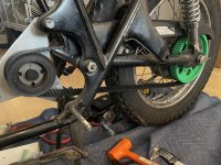
Been riding this build for a few years, finally taking the time to convert the roller chain to belt drive to eliminate the grease but especially the chain noise, which in absence of the engine is pronounced and detracts from the electric motor whir.. Besides sourcing and machining the front and rear sprockets, will need to adapt an automatic tensioner somehow, as well as drop the swing arm temporarily to fit the belt.

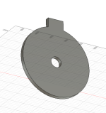
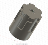
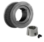
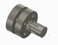
Gates has a good part of what I need, fortunately; going with a 21mm poly chain belt (8mm pitch). Bought a belt and sprocket bushing new, and sourced a NOS front sprocket of theirs from ebay. Looking to get an unbored sprocket for the rear to take to the machinist.
 

Attachments

  • CEFFD092-4776-434F-B051-E5AAAD4C40EA.jpeg
    CEFFD092-4776-434F-B051-E5AAAD4C40EA.jpeg
    798.1 KB · Views: 32
Very nice! I remember your build thread and enjoyed it. Looking forward to seeing how this works out.

For starters, can you share any specs you may have on your motor? RPM, torque at the shaft, ect. Perhaps as well as share your current drive ratio with a chain?
 
Very nice! I remember your build thread and enjoyed it. Looking forward to seeing how this works out.

For starters, can you share any specs you may have on your motor? RPM, torque at the shaft, ect. Perhaps as well as share your current drive ratio with a chain?
Current chain drive ratio is 38/16 (2.375), will be 75/30 (2.5) in the belt drive. Been so long since I calc'd the rpm/torque specs but it's 72v at a 26Kv winding on a Revolt 160-E outrunner so about 1,800 rpm unloaded? Originally had spec'd everything for 60mph but I never take it there, really just use it around the city so may even increase the drive ratio a bit after it's converted. The sprockets are easily interchanged on the front.
 
Not sure if they’ll have something large enough, I just ordered a spline adapter for $14 with free shipping to US from England.
Good resource, the HTD-8M line seems comparable and does have 72 and 80+. I can’t tell if it’s compatible with other 8mm pitch (gates, martin, dodge) or if has is own belt ecosystem so to speak. In any case, it is nearly an order of magnitude cheaper than what gates wants for a plain bore rear sprocket so worth a call.

edit: HTD is the belt profile, differs from and is incompatible with the GT aka poly chain profile. The former while not as strong, is more widely available and may be a better choice for this application.
 
Last edited:
New plan: Poly chain components were too expensive to outfit, though the poly chain belt strength is superior (~2x the strength of the HTD profile). The belt strength of HTD being significantly lower requires a wider belt (30mm vs the 21mm of the poly chain). At a 32/80 gearing gets me just around a 25hp rating for the HTD, which is not as roomy as I would have liked but we’re going with that for about 1/3rd the price overall vs the poly chain setup ($300 vs $1000).

Maedler Drive-train specialist - Large metric inventory - Maedler North America has the belt and the 80 tooth plain bore sprocket for the rear, which I’ll take to the machinist to apply the hub profile from the stock honda chain sprocket. Front sprocket is just a NOS dodge HTD sprocket on a taper lock bushing as before (ebay). Have several ideas for the tensioner but need to see the belt installed before I can commit these further.
 
Last edited:
Where were you looking at for sourcing the poly chain stuff? I'd been trying to figure if a 30mm 8m HTD would be strong enough for motor to jackshaft, if possible I'd rather have 21mm, if poly chain will be stronger than HTD, I'd be spending $ trying to make a 30mm pulley fit the QS180 shaft, so maybe that money saved could go to poly chain? all loose ideas atm ;)
 
Where were you looking at for sourcing the poly chain stuff? I'd been trying to figure if a 30mm 8m HTD would be strong enough for motor to jackshaft, if possible I'd rather have 21mm, if poly chain will be stronger than HTD, I'd be spending $ trying to make a 30mm pulley fit the QS180 shaft, so maybe that money saved could go to poly chain? all loose ideas atm ;)
Gates own website has all the info on their components. They don’t have a lot for HTD options, they seem to have pivoted to their poly chain line. On the PowerGrip HTD design manual you can look at the worksheet for sizing the width of HTD/GT3 belts for your application.

I would have gone for poly chain but for the fact that the rear sprocket sizes (70+ teeth) in 21mm use the 2517 bushing, which is too large of a hole for me to refashion onto my wheel. The cost of the custom order was $500+ just for the plain bore, which would still need to be machined to spec locally, so $$$. That will be last recourse if the 30mm HTD doesn’t pan out.

Also, Maedler pulleys are not flanged at the higher tooth counts so not going with them either. Found these guys though, who claim to have HTD plain bore pulley w/ flange at 84 teeth. TYMA CZ | Drive and conveyor belts, transmissions

fwiw when googling other manufacturers use the formatting convention for better results:
for poly chain pulleys it is 8MX-32s-21 for an 8mm pitch, 32 tooth, 21mm belt width
for HTD it is P32-8M-30 for 32 tooth, 8mm pitch, 30mm belt width
 
Last edited:
Not sure if this is feasible or not, is it possible to get steel disks welded on top of each other?
for a pulley adapter I was thinking about designing something to interface between the motor shaft and pulley, draw up the design, then get sendcutsend to cut a few of them from steel, then stack them and weld together, or cut bolt holes and bolt it all up, hope that makes sense, must be nap time here.
 

Attachments

  • Screenshot 2023-12-22 at 11.05.38 PM.png
    Screenshot 2023-12-22 at 11.05.38 PM.png
    316.3 KB · Views: 7
  • Screenshot 2023-12-22 at 11.11.42 PM.png
    Screenshot 2023-12-22 at 11.11.42 PM.png
    771.8 KB · Views: 7
Last edited:
Not sure if this is feasible or not, is it possible to get steel disks welded on top of each other?
for a pulley adapter I was thinking about designing something to interface between the motor shaft and pulley, draw up the design, then get sendcutsend to cut a few of them from steel, then stack them and weld together, or cut bolt holes and bolt it all up, hope that makes sense, must be nap time here.
Depends on what kind of stresses they have to handle at each interface, and how they're welded, what theyre made of, etc.

For example:

If htey're tack welded rather than continuous, then some forms of stress could bow out the areas between the welds, deforming the shape.

If theyre fully welded, they could distort during welding.

If they're only welded at the outer edge and not the core, then depending on how the core is secured to the shaft (?) they could distort at those edges under stress.
 
I’m not understanding why you need an adapter for the qs motor?
The QS180 has 6 splines, and the useable depth below the clip recess is 10mm, I've been looking for a weld on adapter that fits this pattern, the one I got from the UK is KN16x20 but the female splines aren't wide enough, so was considering cutting steel rings to go between the splines and either bolt or weld onto the pulley, if it'd work would be a lot simpler/cheaper than finding a machine shop to cut splines into the pulley, I think?
 

Attachments

  • Screenshot 2023-12-23 at 9.38.20 AM.png
    Screenshot 2023-12-23 at 9.38.20 AM.png
    1.1 MB · Views: 3
  • Screenshot 2023-12-23 at 9.40.05 AM.png
    Screenshot 2023-12-23 at 9.40.05 AM.png
    517.2 KB · Views: 3
T
Depends on what kind of stresses they have to handle at each interface, and how they're welded, what theyre made of, etc.

For example:

If htey're tack welded rather than continuous, then some forms of stress could bow out the areas between the welds, deforming the shape.

If theyre fully welded, they could distort during welding.

If they're only welded at the outer edge and not the core, then depending on how the core is secured to the shaft (?) they could distort at those edges under stress.
Thanks, sendcutsend can cut 0.5", so maybe less prone to warping,
something like this maybe.
 

Attachments

  • Screenshot 2023-12-23 at 10.25.01 AM.png
    Screenshot 2023-12-23 at 10.25.01 AM.png
    1.3 MB · Views: 5
@quelsurprise I don’t know that you need to be bothered with the splines/channels. I would just use one of them as a keyway and ignore the rest. What is the shaft diameter?
 
That'd certainly make life easier if it can take the load, it's 20mm diameter
shear strength of steel is on the order of 50,000-100,00+ psi. Consider that in most applications the full torque is bearing on a single key width of steel. No different in your case.

Most 20mm taper lock bushings have a 6mm keyway. If your channels are wider or narrower than that you may just need a modified key.

 
Modeled the rear sprocket and applied the hub pattern to the Maedler pulley and printed that. Will use this to check/set belt alignment and position of the front and rear pulleys. Currently printing a mock motor mount to facilitate on the front pulley.

If it looks good and there’s clearance, I think I can pull the trigger on the Maedler. They offer a stock plain bore 80 tooth pulley which I can machine to the sprocket pattern and will save me the expense of having to special order this part.
IMG_3144.jpeg

IMG_3145.jpeg
 
Clearance against chainguard is < 5mm with everything aligned.

IMG_3155.jpeg
 

Attachments

  • IMG_3158.jpeg
    IMG_3158.jpeg
    3.1 MB · Views: 15
The humble belt drive conversion required a level of disassembly and it being winter, I just decided to do a number of improvements at once. In the process, discovered my triple tree was shot, and that it is a common failure on these bikes. Surprisingly, there’s no real replacement part out there for this so I had to draw it up to add to the machinist’s work. I’d also like to get it powder coated along with the frame which is ready to go, but for the order of operations.

If anyone needs a triple tree for Honda cb350F, lmk.

Triple Tree CAD

IMG_3186.png

IMG_3184.jpeg
 
New fiberglass fairing going on. Hopefully will address the most glaring diy aspect of the previous version, which was poorly welded from sheet metal and quite heavy. I affixed some foam to the battery cage and carved it to follow the tank and frame lines. It won’t be perfect but I’m hoping for a B+, A- if the sun and moon align.IMG_3318.jpeg
 
Nice build; looking forward to seeing that fairing completed.
 
Back
Top