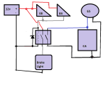
How To Wire a 12V Brake Light and Turn Signals

Except you may need to put the coil in series with the brake light; it depends on the current required to run the light, and the voltage developed across it, and it's resistance vs the coil, etc.

IN parallel like your drawing, if the coil resistnace is low vs the light's, then the current will all flow thru the coil and the light won't light up. If the light's is lower than teh coils, the light will come on but the coil won't trigger the relay. If they're balanced, they'll both work.
 
amberwolf said:
In parallel like your drawing, if the coil resistance is low vs the light's, then the current will all flow thru the coil and the light won't light up. If the light's is lower than the coil's, the light will come on but the coil won't trigger the relay.

Damn. You are the man. How about this then?
 
I'd also like to know this. I already purchased and tested an opto relay (similar to the ones on page 2) but It would be nice if I didn't have to splice into my throttle +5V. Cam we get away with just a basic spst NO relay?
 
More parts-n-such

DrkAngel said:
Great Project item
Plastic base removable!
12V ~250+ lumen(?) 2x Cree led w/diffuser dome

- $4.42
Update:
Playing with these, building a turn signal led upgrade.
Finally noticed that these are dual mode.
1 pos wire uses .5w and the 2nd uses 1.5w 1x - 3x brightness!.
Great for running light and turn signal ...
or tail light and brake light.
And
Price dropped to $3.60 per pair!

I am using the ...
12-24V flasher (also dimmer strobe pulse) variable speed mode etc.
It does maintain mode-setting when power removed for use as component.

- $1.19 / shipped

Flash mode and speed are adjustable.

Ordered up a lights, turn, horn control module ... several choices

- <$7

Index

12V 48 led flexible Running\brake\turn < $2
Great for across rear rail of ezip rack! Shows some turn around sides. Supplemented with clear tape to attach.

 
MJSfoto1956 said:
amberwolf said:
In parallel like your drawing, if the coil resistance is low vs the light's, then the current will all flow thru the coil and the light won't light up. If the light's is lower than the coil's, the light will come on but the coil won't trigger the relay.

Damn. You are the man. How about this then?

Would this relay do the job (the 5V version)?
https://www.ebay.ca/itm/2Pcs-G5NB-1A-E-Relay-DC-5V-12V-24V-SPST-NO-Omron-G5NB-4-Pins/183425565485?hash=item2ab504032d:m:mfj1fW8spUTnHTw8cWXB0eQ:rk:1:pf:0
 
Bump for my last couple of questions...
 
People are overthinking this too much.

brake-lamp.png


All we are doing is closing two circuits, the cutoff and the lamp, by one control input. No need to do sketchy stuff with the ebrake cutoff signal, or mixed voltages, or series connecting loads with relay coils (this will burn it out usually). Just an old fashioned DPST relay does it.

Earlier people mentioned using 12V batteries as a source, no need either, there's lots of DC-DC PSUs that can take a wide range and put out 12V stable... MeanWell make good ones.
 
I've just attempted the simple relay solution but I couldn't get it to work. I used an SRD-05VDC-SL-C relay but the 5V brake signal from the controller did not appear to activate the relay's coil.

If we go back to page 1:
The currents through the ebrake switches are tiny (a few ma) and the switching may be provided by mechanical or magnetic switches or electronically via hall sensors (e.g. HWBS - hidden wire brake sensor).

I measured the current from the brake signal and it was only 0.56 mA. That was on a WCEC Xia Chang type controller. I can't seem to find a relay that would be that sensitive.
 
I tested the relay again with a paralleled +5VDC from throttle cable. The relay appears to function now! Is this because the relay coil now has enough current to be powered? This leaves me with another question: what is the purpose of using the relay + board that was first mentioned in this thread? I don't understand that part.
 
Teklektik,

Thank you for the excellent tutorial. It only took me three days to figure out how to make my relay work the way its supposed to :oops:

Anyhow, I have a question for anyone who knows more about circuits than me (pretty much everyone). I am using the 5 volt version of the relay shown on page two of this thread. Bought it before I really knew what I was supposed to get. I was having trouble getting the relay to work when I wired it up the way it is shown. I was powering the relay from the Cycle Analyst 5V output, and the relay would close, but the CA screen would increase in brightness and the letters would disappear :?

I put my trusty multimeter on the circuit and found the voltage would drop to about 2.85 volts when the relay was activated. My next step was to power the relay from an external source. SUCCESS!!!!! It worked fine. Now my problem is that I don't have room to put in a DC converter to supply 5 volts. I cranked my power source up to 12V and the relay still worked, but its LEDs got pretty bright. I would worry that the relay would fail quickly, or I would just run it straight from 12V.

So my question.. Can I just use a couple of resisters and create a voltage divider to reduce the 12V I am feeding the CA to 5V? Or is there some way to calculate a value for a single resister in series from the voltage drop that I saw.

Thanks in advance....
 
Disregard my last post,,,

Two reasons. First I think the load placed on the 5V coming through the voltage divider from the relay coil might generate a bit too much heat in the resistors. Secondly... I was able to find a 12V optoisolator relay with the PROPER 22Kohm smd resistor on Amazon. Will be here in a couple of days, then it's a simple swap and done :D

Once again, thanks for the great thread on this subject :thumb:
 
Dang,

My new 12v opto isolator relay showed up. Unfortunately it has the 10K resistor instead of the 22K one. So back to square one. I could swap in a 222 resistor in place of the 105 one, but it's unclear whether or not additional changes would also need to be performed..... Or, i could just hook 12V into the V+ instead of 5V. Like I said, it works fine, but I wonder about the longevity of the 5V relay. I guess since I have a pair of them, I could just go for it and buy time to find the correct relay. What are your opinions????
 
ronncat said:
Unfortunately it has the 10K resistor instead of the 22K one. So back to square one. I could swap in a 222 resistor in place of the 105 one,
105 is 1,000,000 ohms (10 with five zeroes), not 10,000 ohms (10K). 10Kohm would be 103.
222 is 2,200 ohms (22 with two zeroes), not 22,000 ohms (22K). 22Kohm would be 223.


Or, i could just hook 12V into the V+ instead of 5V. Like I said, it works fine, but I wonder about the longevity of the 5V relay. I guess since I have a pair of them, I could just go for it and buy time to find the correct relay.

12v is more than twice the voltage (2.4x), so it will cause more than twice the current flow as well, which will cause that much more heating in the coil. If there is sufficient cooling, or low enough duty cycle and enough thermal mass, it'll probably be ok, but if the heat builds up fast enough it can damage the coil windings.

I have a cheap 24v kickscooter with two 12v relays for on and off control. One relay is for throttle, and the other for braking. IIRC, the brake relay is always on as long as power is on, *except* when brake is engaged. That relay coil is burned out. I've seen that sort of thing in other devices that overcurrent relay coils. Note that the other relay that is only on for short periods still works fine.
 
Amberwolf,

Thank you for your reply. In my haste to post that last post I had a few typos. It should have read 2.2Kohms, not 22 , and 103 not 105. :oops: Thank you for the lesson on resistor values though. It will come in handy.

Anyhow, I messed around a bit by putting varying voltages through both the 12V and 5V relays. I placed several different resistors in series while running 12V into the 5V relay. Couldn't get the relay to latch with much less than 10.5V post resistor or so. I guess the resistors limited the current to the relay coil. I was just going to run the 5V relay with 12V, but figured I should just hook up the 12V relay to see what would happen...

Darned if it didn't work :shock: So I guess that this particular 12V relay with the 103 smd resister is a go :D
 
Wow. What an amazing thread - super informative and such a time saver.... I spent days trying to nut out a 5v GND switched brake signal without a lot of luck. I joined Endless Sphere just for this thread alone. Many thanks to all the contributors!

....but, I have a question. On the CAv3, the tripwire system daisy-chains the brake cut-out sensors together, with the gear-change sensor. Has anyone got a system worked out where the front or rear brake levers trigger the brake light, but the gear-change sensor doesn't, while any one of the three still cuts out the motor?
 
Depending on exactly what you have for wiring/etc., you could use a diode in the brake switches in their wiring to the light, so they will ground or pass power to the light, but the gearsensor won't. Basically making a "diode XOR" switch, excluding the gearsensor. This requires not directly connecting the gearsensor switch directly to the other two. the GS would connect directly to the CA, while the brakes would connect to one side of a diode, and the other side goes to the CA. Polarity of the diode depends on waht's being switched (5v or ground).


Alternately you could use a DPST relay to do the same thing, with the gearsensor wired only to the CA, and the brake switches would then switch the relay (both wired in parallel with each other, and then those in series with the relay coil). One of the contact sets would switch the CA input, and the other would switch the light. The relay will probably draw more current than the CA 5v output can handle, so you would want to power the coil from the same source as the light(s). If taht's 12v (13.6v for automotive lights) then a 12v relay will work, and those are easy to find even in very small (sugar-cube size pr a bit larger) forms. The advantage of this is it completely separates your lighting system from your traction and control system, so no voltage can ever accidentally get thru into the CA and damage anything.
 
Thanks for your prompt reply AmberWolf.

After doing a bit of reading to learn how to use a relay as an XOR gate, I read and re-read your 2nd paragraph then drew what I think you meant up so I could walk through the circuit and understand how it would work:
B1WqkFB.jpg

In these diagrams, the blue boxes are just visual shorthand for the opto-isolated circuits described earlier in this thread, where a GND signal from the brake levers triggers a 12v supply on the output.

I can see how 12v on the left side of the relay coil and GND on the right, triggered by the brake lever switches, would charge the relay coil and close the contacts, allow the GND from the brake levers to pass to the CA which cuts the motor and also supplies power to the brake light. However, if there's 12v on the right, triggered by the gear change sensor, either relay coil gets charge (albeit in reverse polarity) closes the contacts and then powers the light, or if both left and right sides of the coil are powered, the coil has no voltage drop across it, doesn't close the contacts, and while the CA still cuts motor because of the direct connection from the gear change sensor, the brake light doesn't come on despite the brake levers switches being closed.

I'm quite sure this is not what you meant AMberwolf... but with my limited knowledge (electronics was a looooong time ago for me) I'm struggling to understand. Sigh.

However, you did give me plenty to think about, and I like your idea of using the relay to separate 12v from the 5v CA and 52v traction components.... so I came up with an alternative design that looks like it might work?
gaYEKJE.jpg


I put a diode in front of the brake side of the relay to isolate any charge from the right side, and took a feed prior from the opto-isolated 12v GND triggered output straight to the brake light. Not needing a DPST relay, its now a SPST 12v relay. Now charging either side of the coil (but not both) will close the contacts and cut the motor at the CA. Only the left side can power the light, because of the diode, and if both sides of the coil are charged, the brake light still comes on, the relay doesn't trip, and the motor cuts out due to the direct connection from the gear change sensor.

Does anyone want to challenge this schematic and tell me it won't work?
 
I can't see your images, but this should be all you need to make it work. Everywhere there's a dot on wires crossing, they're connected at that point. If there's an arch, there is no connection. The diode on the relay coil is just to prevent voltage spikes from the relay coil (during switch off) feeding into the system supplying it signal/power.

Using a DPST / 2P1T / 2PST relay lets you use the lighting and ebrake systems as separate but simultaneously controlled systems.

So the only two parts you have to buy are a small diode (1n4148, 1n4001 (etc)) and a DPST relay. A DPDT relay can be used, too, you just won't use the NC contact on either pole, just the NO one.

If you have any old UPS power backup units laying around, there's almost certainly relays and diodes in there you can scavenge (I did this recently for the relays on my proportional regen brake lever system, which works very much like what you need).
Isolated brake light and gearsensor relay..png


FWIW, adding the images directly to your post via the Attachments button means that anyone can see the post can also see the image, and they are stored with it so not lost whenever an external hosting site goes down, or changes their terms of service, etc.
 
Amberwolf, thank you very much.
I breadboarded that circuit up today and works a treat.

...and thanks for the advice on attachments :)
 
Supplementary questions to those out there fitting 12v systems to their ebikes...
Did you measure battery draw down by installing a shunt? Do you run a phaserunner controller? How did you do it?

I have a 52V main battery driving a Phaserunner MT controller with a Cycle Analyst v3 display. The controller has a shunt in it, but it also outputs just a small 1A load at supply voltage for subsystems. Thats 4A at 12v and my motorcycle horn draws 4A at 12v all by itself, let alone the 2A or so for lights and everything else. So I have a DC-to-DC step down transformer, and I'm not sure I can use the controller's built in shunt any more.

Why? Looking at the controllers other outputs, there's nothing suitable to attach the converter to, so I think I have to splice the controller feed near the battery and tap a supply for the converter from there. But that means taking amps out of the battery before the shunt, so I can't measure accurate battery draw down any more.

I think I'll have to install a shunt (Grin sell one) on the ground wire, close to the battery, before the tap for the 12v feed, and run the shunt voltage wires down to the cable that has the signals from the phaserunner, cut the blue and white wires (pins 3 and 4 according to the Controller CA plug pinouts attached below) in that wire bundle and splice in my voltage signals from the new shunt, so the CAv3 can correctly measure battery draw down...

Before I go buying shunts and cutting wires, does that sound like a reasonable plan?

JST_Pinouts.jpg
 
Can someone please help me?

I followed your original post and bought the octa relay. I wired according to the schematic however I can’t get the relay to run on low signal. When I jump the 12v to the control in the high relay works and my brake light came on but when I tried to do the low signal input nothing happened. I tested the output on my brake and when I pressed the brake the brake go to 0V and when I not the average voltage is 100-300mv. Would someone please help me with it ?

Thank you so much
 
Phamd4 said:
Can someone please help me?

I followed your original post and bought the octa relay. I wired according to the schematic however I can’t get the relay to run on low signal. When I jump the 12v to the control in the high relay works and my brake light came on but when I tried to do the low signal input nothing happened. I tested the output on my brake and when I pressed the brake the brake go to 0V and when I not the average voltage is 100-300mv. Would someone please help me with it ?

Thank you so much

Does your relay board have resistors with the right values on it it? See this post early in this thread...
https://endless-sphere.com/forums/viewtopic.php?f=2&t=75171&start=25#p1167956
 
I'm honestly a bit surprised that no one has brought a plug and play solution to market yet. It would seem like a reasonably easy thing for a company like a controller manufacturer to churn out. A box with high voltage inputs, outputs for lights, i/o for some switches. There is clearly a demand.
 
Hi Guys
Does anyone have a link to where I can buy the opto relays from preferably in the UK.
I'm struggling to find them
 
Back
Top