Increasing controller input voltage - Infineon 4 / Xie Chang KH6XX

pwd

10 kW
Joined
Oct 11, 2011
Messages
799
Location
Ontario, Canada
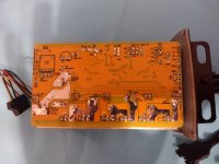
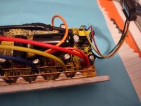
I have this Infineon 4 / Xie Chang controller which was advertised as 48V and I've been using it up to 57V without issue. I'd like to get it working on a 72V setup (84V max).
IMG_20200901_141000 (1).jpg
IMG_20220308_095929777.jpg
IMG_20220308_204652408.jpg
IMG_20220308_204630978.jpg

It is programmable via the xpd software.

The good news is that the two largest capacitors and k150e10ne mosfets appear to be rated for 100V. I've read that there may be a resistor that steps down the voltage to a regulator that needs changing when increasing the controller voltage. I've also read that some Infineons don't work that way?

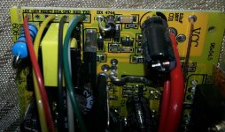
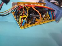
The pad for the blue resistor on the board is marked "R01A 100/1W"

Can anyone advise on if the resistor needs changing and if so how do I determine what to replace it with?
 
This one has a switching regulator (that's what that transformer is for) instead of the linear regulator to convert battery voltage to 12v and 5v. So the resistor trick may not work.

The resistor in the linear regulator drops some of the battery voltage across it, leaving only as much as the linear regulator chip (usually lm317) can handle; the voltage across the resistor varies by current flow thru the resistor.


The switching version may operate differently, even though it also has a large resistor. If you measure voltage across the resistor while the controler is powered by the bike battery, you can find out how much is "absorbed" by it, and thus what's left on the input of hte swithcing regulator (assuming the resistor is on the input side). Then use that plus it's resistance and the full battery voltage to create a formula to figure out what resistance to use to absorb all but that amount when using your higher voltage battery.

If it doesn't work the same way the linear one does, then you could still damage the switching regulator when using it with the higher voltage battery, even with the resistor changed to the necessary resistance. :(
 
I powered up the controller with 53.7V and measured 1.746V across the blue 100ohm resistor. So does that mean that 51.954V is going to the regulator (which I'm guessing is that black and yellow component)?
 
pwd said:
I powered up the controller with 53.7V and measured 1.746V across the blue 100ohm resistor. So does that mean that 51.954V is going to the regulator
Probably, but without knowing the design of the regulator (at least it's input side), and how it is supposed to work, you cant' really know why it is that way or exactly how to alter it to make it work with a higher voltage. You can guess, and you can try it the way it would be done with the linear regulator type, but that could destroy it if it doesn't work the same way.

It might work fine with no modification (if it's voltage input range is wider than the controller specification like the capacitors and FETs are), or it might smoke at 0.1v above it's stated specification even with a resistor change, or anything in between--with just hte info we have right now, can't really answer that without testing. :(

I'm not expert enough on SMPS regulators to figure out the circuit they're using and how it works; I can only make educated guesses based on past experiences and devices, especially without a schematic.

It's even possible that resistor has nothing to do with the input of this regulator, and is used on it's output, or somewhere in between. To find out, you'd have to trace out all the parts on that area of the board from the battery voltage bus all the way to the 12v and 5v supply lines on the rest of the controller, and draw it up to see what connects where.

The input circuit probably starts with the smd components near the big electrolytic C01 (by the main battery positive wire); that is probably the startup and oscillation circuit that drives the large transistor next to the transformer. The resistor R01A is more likely to be on it's output side, along with the diode(s) and small electrolytic, and the small 3-pin device (which from the nearby markings is probably an lm7805 to derive 5v from the 15v the SMPS outputs (according to the markings on the edge of the PCB).


(which I'm guessing is that black and yellow component)?
That's just the transformer. That whole corner of the controller is the switching regulator. (you can look up SMPS / switched-mode power supply for info on how various types of these work; they're much more complicated than the linear regulators, but much more efficient as well, and can often handle a wider input voltage range without affecting their output as much).
 
Thanks for your thoughts amberwolf. It seems I have more reading to do, since my knowledge it too basic for this. I mostly see what you are saying though; without the schematic; we are just guessing.
 
Bump - I'm still looking for how to determine the max input voltage of this controller

I've found some hints here, but nothing confirmed:
https://endless-sphere.com/forums/viewtopic.php?f=2&t=59301#p1705513
https://endless-sphere.com/forums/viewtopic.php?f=2&t=28997#p1705583

someone out there must have experience with this controller?
 
I took a chance and decided to try the controller on 78V; it is working without any modification :bigthumb: . I have yet to try it on a full charge (84V) however. The regen does not work past 77.6V though. Strange thing is that I have a larger 18 fet KH606 and the regen is working past 77.6V. Could that be because the 18Fet version has had solder added to the shunt causing the regen to work beyond the the 77.6V regen limit?
 
The shunt (to measure system current in the battery negative wiring) doesn't know or care anything about the system voltage, and the stuff that monitors system voltage doesn't know or care anything about the shunt. ;)

The system probably has a firmware setting for it's regen voltage limit to protect against the voltage spikes that could destroy FETs, etc. When you use regen at higher voltages the feedback from both the regen itself and the sudden spikes you can get when the BMS in a battery shuts off could easily be high enough to blow up the FETs.

Some systems dont' have firmware limit protection against this, or have a higher limit set that doesn't give enough margin (which is one reason some controller "brands" fail more often when used in regen systems at higher voltages).

Some use a voltage divider fed from the main battery line to monitor system voltage; if you don't care that the MCU won't know what the system voltage actually is (no HVC or LVC protection), and if it will operate without that input (doesnt' shutdown due to LVC, etc) you could cut the trace from the MCU to that divider, and it would remove all those limits (in that the MCU wont' know what's happening to system voltage...but it can't protect itself or anything else either). If it wont' work because it shutsdown from LVC, you can measure what the voltage is at the divider where the trace comes from, then create a different divider that runs off the 5v (as long as 5v is still available when system is in shutdown), that outputs that same voltage to the MCU's monitoring input. THen it will "always" be the same voltage, never changing, and the MCU will never shutdown or disable anything due to system voltage changes.

It won't protect anything from them either, but as long as that doesn't matter, it's a solution to the regen voltage limitation. ;)
 
Ah I see, the shunt is not relate to voltage monitoring.

I did some testing on the larger KH618 controller controller where regen is working above that 77.6V limit and it appears that the low voltage cut-off is also raised quite a bit. Example: Setting the low voltage cut off to ~51V (via XPD controller software) cut's power when the battery is at about ~77V. Would that mean that the controller has had it's voltage measurement modified somehow (maybe like how you described cutting the trace to the voltage divider)?

I've also come across the "R12 High Voltage regen" mod for older Infineon 2 and 3 controller: https://endless-sphere.com/forums/viewtopic.php?t=23745 Does anyone know if you can do that with the Infinfion 4 style controllers?
 
pwd said:
I've also come across the "R12 High Voltage regen" mod for older Infineon 2 and 3 controller: https://endless-sphere.com/forums/viewtopic.php?t=23745 Does anyone know if you can do that with the Infinfion 4 style controllers?
No idea, but that is probably modifying the voltage divider that the controller monitors for all battery-voltage-related things (I can't imagine it would monitor more than one?).
 
Back
Top