Inductance What is it what does it do? Collosus has 8uH!

Thank you rhitee05, that's an interesting report. Pretty clever of him to illustrate it the way he does. I've read the chapter which discusses what you bring up in your post. I may read more later, it's an extensive report.

Meanwhile, I've expanded my model, and been playing with advance. I can pretty much confirm his findings, that there is a region with more or less constant power with a need of constant increasing advance. With sine wave drive, there is (at least) a region of pure constant power. With the square wave drive, power is slowly decreasing with RPM.

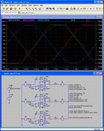
I was able to run my square wave driven model at over nominal speed; 100V EMF, 70V battery voltage and get about 3kW (with 100uH).

Some of my points hasn't been valid. But it's still true that high inductance puts a power limit on the motor. It reaches the constant power region at a lower RPM. I may also try to show that the motor gets less efficient at high RPM with higher inductance because of resistive losses caused by the high RMS currents when using advance.
 
Interesting post from another thread:

justin_le said:
swbluto said:
Since ebikes.ca has the L and R values for the motor's, I'll try to take a worst case. Let's see... if you increase the winding count, the inductance goes up and the resistance goes up. The inductance goes up linearly, while the resistance goes up by a squared factor, so a higher winding will have a lower L/R ratio.

This is not true. Because you need to use a thinner gauge wire to get more turns and increase the winding count, the winding resistance R also increases at the square of the turns. So the L/R time constant is the same regardless of the winding.

If you are concerned about the magnitude of the ripple current, then indeed a lower turn count has less inductance resulting in the phase current going up and down more during each PWM cycle than it would for a high turn count motor. However, the overall DC magnitude of the phase current is higher with the low turn winding as well, so the ratio of the ripple current to the phase current again remains identical regardless of the winding.

But, I wonder how low RC motor's L/R ratios are? If they're significantly lower than the worst case hub motor, then peak phase currents could be the essential problem.

http://endless-sphere.com/forums/viewtopic.php?f=2&t=19590&start=105
Quick measurement of a Turnigy SK6364-230 gives R=0.0297 Ohm, L = 37 uH (+-2uH), L/R = 1.25 mS, so same ballpark.

-Justin
 
My LTspice model is getting pretty usable. I've made everything parametrized. If you for example change the parameter motorEMF, then the motor frequency and the simulation period is changed along. There are a number of parameters describing the motor and the controller, and their names should be self explainable.

If anyone is interested in trying it, I've attached it below.

When using PWM, there may be a problem. I've probably spent three times the time it took to make the actual model, to look for that problem. I can't find anything wrong. The problem is that the waveforms of the currents are a little unsymmetrical. The positive halfwave have a faster rise/fall time for some reason. The average currents are the same, though. The waveforms are also pretty rough, IMO. It may have something to do with how it is PWM:ed. It's done the same way as in some commercial controllers, that is, one phase lead is floating, one is tied to +, and the third one is PWM:ed.

The parameter usePWM is set to 0 by default, but can be changed to 1 to enable PWM.
 

Attachments

  • motor_sim_0.1_noPWM.PNG
    motor_sim_0.1_noPWM.PNG
    29.4 KB · Views: 1,961
  • motor_sim_0.1.asc.zip
    1.6 KB · Views: 69
Arlo1 said:
There is something WAY WAY off with you calculations, Unless you have used a stupid low voltage for the calculations.
I have made over 6.5 HP at the rear wheel with a 255uH inductance motor! Im going back to look again.

You were right. It seems the previous model was off with a factor of 2. I'm not sure why, really. Probably has got something to do with simplifying it too much. My current model shows power in the area of 7kW (from 3.5kW) with all else the same, except adding phase resistance.
 
Ok that sounds better i used 100v to get 6.5 hp at the rear wheel. And there would be more if the resistance was lower!
 
bearing said:
When using PWM, there may be a problem. I've probably spent three times the time it took to make the actual model, to look for that problem. I can't find anything wrong. The problem is that the waveforms of the currents are a little unsymmetrical. The positive halfwave have a faster rise/fall time for some reason. The average currents are the same, though. The waveforms are also pretty rough, IMO. It may have something to do with how it is PWM:ed. It's done the same way as in some commercial controllers, that is, one phase lead is floating, one is tied to +, and the third one is PWM:ed.
Bearing, your model correctly simulates what is happening in some commercial controllers. I have experienced this during the development of my controller too. The asymmetry comes from the difference of current decay time through the inductor of the floating phase which is caused by always switching the same side of the bridge (Top or Bottom). This effect is worse for high load and low speed use cases where the PWM duty is low and current high. It causes serious sync issues, low efficiency of the controller and most cheapo RC controller to blow up...

The solution is to correctly alternate Top or Bottom side switching to maximize the neutral voltage since the rate of change of the "floating" phase inductor current is proportional to it.

See the optimized switching sequence below. Note this model also include synchronous switching which significantly improve efficiency and also permit regenerative breaking :)

motor_sim_08_ES_zpsbb2d897d.png


Model attached here:View attachment motor_sim_0.8_ES_public.zip
 
I may have another explanation why cheapo controllers blow up with low inductance motors. It's actually very simple.
And let's say we have a motor with inductance of 10μH... Now, we would typically get a very high ripple current, like 100A or so, just to spin it without any load. It would be heating up, but spinning fine. The problem, I believe, is in difference of waveform shapes.
Let's say our controller has a trapezoidal waveform with synchronous power stage and our motor is sine. Let's say we have a 48V battery, motor resistance is 20mΩ and inductance is 10μH. And our PWM is at 20%. Here is what we get:
n93ZMc5.png


At 50% PWM, motor is spinning at ~half max RPM, so blue line shows BEMF shape. Orange line is an integrated PWM shape (so half amplitude at 50% PWM).
Notice that BEMF shape does not match with PWM (controller's output waveform) shape: in some areas controller's output is higher, and some - lower than BEMF. What that means that motor is actually running in both modes at the same time - motor (green area) and generator (red area, regen). And these both modes are drawing huge currents, up to 500 amps.
With 16kHz 48V 50% PWM and 10μH motor, our ripple current is not so high - 22A RMS. Well, too high for reasonable efficiency, but not "damaging" high.
Gray line, however, shows phase current, caused by waveform differences. This goes up to 500A and RMS current is 263 Amps!!

I believe this explains why many controllers go bang even at no load conditions, or some time later.
This also explains what happened to "Golden motor 500A" controller during my test several years ago, when I hooked up to CA80-100. The controller was "pure sine wave" and motor was very close to trapezoidal waveform. I did not even put any load on it, just spun up several times and bang, controller had a shorted phase.

Does proper vectored control take care of this? That golden motor controller was marketed as "vector control".
 
Full disclosure, I do NOT understand the first thing about inductance. That being said...here is an email I got about inductance

The long version is here: http://en.wikipedia.org/wiki/Inductance
In short, if there was no inductance, controller would see the motor as a resistor. Resistance of the motors is somewhere around 2mΩ. If we have 48V battery, we get short pulses of 48/0.002=24'000 A of current without even applying a load or going to full throttle. This fries most of the controllers.

Inductance is measured in Henries and it evens out the current pulses to normal levels. Desirable motor inductance is around 50-150μH. Figures lower than 20μH, apart from causing excess heat, start to make serious problems. Some large RC motors and, especially, various "cheap" coreless motors have inductances less than 5μH. Also you don't need inductance too high because it will give problems at high RPM.

how do you measure inductance?
I used an el cheapo inductance meter I bought of ebay, measures my marked inductors I have laying around with decent accuracy

what are the high and low limits of micro-Henries that are safe?

I don't know

When inductance is too low, what happens to kill controllers?

You can run into a situation where current limiting does not kick in fast enough and overshoots. The lower the inductance the faster the overshoot rises. The rate at which the current rises is known as di/dt, current over time

When inductance is too high, how can that hurt the controller?

I don't think it will, but I'm not sure. High inductance would probably be a very slow wind motor and very easy to drive for a controller but it will reach it's current saturation faster

What can be done in the design of a motor to have "good" inductance?

Have someone who knows motor design do it, that would not be me.

What can be done to an existing motor to raise/lower inductance to get it into the "good" range?

you can add air core inductors to a low inductance motor to increase inductance making the motor easier to drive, Arlo1 and I believe John in CR have both done this, there is a thread somewhere

I don't know if the design of the cromotor has any relevance to smaller non-hubs, but...I recall Cromotor V1 has an inductance of 120-uH, and when they were designing to improve several aspects of the V2, they purposefully raised the inductance 145-uH.
 
bigmoose said:
Thud, First, these guys have some off the shelf laminations: http://www.rbourgeois.com/induction_motors_laminations.a234.en.html

Second, here are some photo masks that are relevant to other processes. One would have to test to see if they were acid stable. I would bet most UV cured resins are.

Here you go USA Source Photoresist, "use on any metal with most any etchant" http://www.capefearpress.com/puretch.html

China Source Photoresist http://www.green-technology.net/english/product.asp-prono=11_SP_A400.htm
PCB etch resist should work http://www.thinktink.com/stack/volumes/voli/store/catalog.htm
http://www.ikonicsimaging.com/photoresist_film.php
http://www.problast.com.au/getting_started.html
http://www.granthams.com/page2.html

As for lamination materials it is very important for the power levels that you want to go to that you use Si bearing steel or better yet Cobalt bearing. You need good magnetic properties (flux) and high resistivity to kill the eddy currents.
Here is a link to lamination material properties. Also do not forget that the laminations need an insulation coating. The thinner the better. Protlam will get your started:http://www.protolam.com/page7.html

Here is what I have hanging around on laminations from various sources:

EDIT: Whooppee! I found the reference for you that the pix below came from. Carpenter Steel Tech Center.
http://www.cartech.com/techarticles.aspx?id=1624

This is what I am talking about with respect to the advantages of SiIron: "Silicon Core Iron "A" has magnetic properties like those of electrical iron. However, it has electrical resistivity of 25 -ohm-cm, compared with 13 for electrical iron. Silicon Core Iron "A-FM", a free-machining variation of the alloy, has nearly identical magnetic properties.

Silicon Core Iron "B", with electrical resistivity of 40 -ohm-cm, has been used in applications requiring very low hysteresis loss, high permeability, low residual magnetism and freedom from magnetic aging. Silicon Core Iron "B-FM", a free-machining version, is also available.

Silicon Core Iron "C" offers the maximum electrical resistivity at 58 -ohm-cm. It also has maximum initial permeability, minimum hysteresis loss, low residual magnetism and negligible magnetic aging."

View attachment 1
View attachment 2

With the cost of custom stators and laminations being so much is it possible to make a decent powder core stator using some of these metals? Or maybe cobalt iron alloy?
 
Back
Top