Infineon Speed Circuit

philf

1 kW
Joined
May 28, 2008
Messages
332
Location
Burlington, ON (Canada)
I'm just wondering if anyone is actually USING the supplied speed output line on the Infineon controller (the lone blue wire).

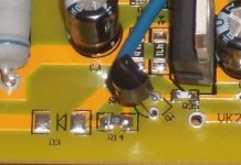
I ask, as I was looking at the smaller (36V 350W) controller and recognizing that the missing functionality is easily added to it (the pads are there - just missing 2 resistors and a transistor). However, in looking at how the circuit was set up on the larger (both the 72V and 48V) Infineons, I couldn't help but feeling that someone goofed. There is an afterthought jumper added to the back of the board to provide 5V to the the output section, but the result isn't what one would expect.

For reference, here are the top and bottom of the board:

SpeedComponents.jpg


SpeedPower.jpg


I've diagramed the resulting circuit, and it looks like this as wired...

SpeedCircuit.jpg


That looks pretty goofy to me. I would have EXPECTED this...

SpeedCircuit2.jpg


Is it just me?
 
philf said:
I'm just wondering if anyone is actually USING the supplied speed output line on the Infineon controller (the lone blue wire).
Lone blue wire is essential for using the CA. Gosh :roll:

CA_Connections.jpg


from ... http://endless-sphere.com/forums/viewtopic.php?f=16&t=7361#p110932

-K
 
Knuckles said:
This is essential for using the CA!

EXACTLY!

Hence my question - does it actually WORK as shipped? Asking that little transistor to try to sink the entire 5V bus in an attempt to pull the speed line low looks a bit futile. Might create a bit of noise, though...
 
Let us not seek the XXXX's answer or the (other MoFo) XXXX answer, but [rather] the right answer.
Let us not seek to fix the blame for the past.
Let us accept our own responsibility for the future.
John F. Kennedy

Sh*t ... I DON'T Know! :cry:

My "STOCK" Response ...
[youtube]4e9CkhBb18E[/youtube]

OK! I guess I have ANGER issues maybe? :shock:
 
ALL RIGHT! I NEED GLASSES (The ones in the avatar are safety glasses).

The "jumper" isn't a straight wire... It's a tiny 10K resistor.

This changes everything, so you can pretty much disregard this whole thread :)
 
Does this help?

R14_Q1.jpgHey ... Same thing! Good Golly!
BTW ... Your Avatar pic is FREAKY! :eek:
philf said:
ALL RIGHT! I NEED GLASSES ... you can pretty much disregard this whole thread :)
NEVER! :twisted:
 
Knuckles said:
Does this help?
Actually, No. :)

That's just showing R14 and R35 again. :roll:

I was referring to THIS (and, weirdly, it's much easier to see in this picture than it is in real life, due to the lighting :oops: ):

SpeedPowerRes.jpg


On the other controller, there's no indication that there's ANYTHING inside the heatshrink - but there is. :D
 
Hey Dude! Where's My Car! (Oh Yeah ... I'm sitting on it!)

Hey maybe you have a use for the "lil blue wire"?
http://endless-sphere.com/forums/viewtopic.php?f=2&t=8610&p=131511#p131511

"HECK! For all I know it might work on ANY "Speedo-Meter" thingy."

Master philf ... What you think man?

btw ... It's not the Glasses ... It's the "Maniacal Grin" :shock:
 
Yup - that's exactly what I'm talking about (and yes, it will work) - and is the whole point of this thread...

The "blue wire" doesn't exist on the smaller controllers, and it was the process of looking at the circuitry supporting its function on the larger units that gave me pause to consider how it was laid out.

Happily, the pads are present on the small units - just missing two SMD resistors, an SMD transistor, and one regular axial resistor (and, of course, a piece of blue wire).

350w%20blue%20wire.jpg
 
philf said:
(and, of course, a piece of blue wire).
Be sure to let the "Dummies" know that the wire must be BLUE or it won't work! :D
 
But then you couldn't do this on weekends ...

[youtube]j82GKTgVDkw[/youtube]
 
K__4 said:
My EB806XC with timestamp of 081218 was eqipped with the blue wire.

Georg

Well, now... The board I pictured has a datestamp of 081218, too!

Interestingly, Keywin's pictures on his eBay listings show these controllers WITHOUT the wire, so I wasn't surprised not to see it. The wire would actually be installed by hand, but it looks like the setup at the factory actually has the pick n' place machine set up to populate these components - if it's given the parts :)
 
Hello again

The controller from crazyman arrived germany. And now we do not now to connect the brake-light-switch.
He stopp the motor by braking. The engine is a scooter. We have only one wire to connect. This wire has 12 Volt every time by "ON" By braking 0Volt. This wire must stop the motor by braking. Is there something wrong?

Needs the controller from crazyman 12Volt to stop the motor on the lone wire (E-Brake). :roll:
The other the other way.

MFG
Joehannes
 
philf said:
Yup - that's exactly what I'm talking about (and yes, it will work) - and is the whole point of this thread...

The "blue wire" doesn't exist on the smaller controllers, and it was the process of looking at the circuitry supporting its function on the larger units that gave me pause to consider how it was laid out.

Happily, the pads are present on the small units - just missing two SMD resistors, an SMD transistor, and one regular axial resistor (and, of course, a piece of blue wire).

350w%20blue%20wire.jpg


Have you tried (I'm sure) adding the 2 resistor missing and the transistor to see if it work? (I need to install a CA on this 6 fet controller...that didn't have the blue wire, just like you :) )

Robin
 
Hi,

i have the same problem, is there no one who can confirm that it works if you add the missing smd parts (and the blue wire of corse)

Could we bypass this problem by using a reed contact and setup the CA-DC like the CA-DC with speed sensor

Please help us to fix this problem

Greetings from Germany

Markus
 
Hi,

i added the resistors and the transistor and it does NOT work? grrr.....

Has someone an idea how i can add the speedinfo to my CA-DC? How does the CA-DC with speedsensor work (with reed contacts) ?

Markus :(

Yes I did it with a little help from ebikes.ca (thanks to them)

I got a KISS (keep it simple and stupid)

WE DO NOT NEED A SPECIAL SPEED IMPULSE FROM THE CONTROLLER !!!

We can use one motor hall sensor, we only must setup the CA "#Poles" value and the "wheel size". I use my Garmin GPS as a reference to set the 2 CA parameters that the speed match.

Markus ;)
 
Back
Top