lightbulb010
10 mW
Hello, fellow ebike enthusiasts. I'm starting this thread to document my ebike build that I will be working on (slowly) over the coming months. My basic plan is to build a steel frame with a swingarm and use MTB forks for the front. It will be mid drive with a moped hub for the rear so that I can use two separate chains. One for the motor and one for the pedals. 16" rim on the rear and 18" rim on the front(so 20" and 22" in bicycle terms) I will utilize the hub brake on the rear and a disc(possible double disc) up front. I'm considering the qs165 or qs138. So the battery will be 20s. I'm thinking 8 parallel packs of 20 molicel 28b. I'm still debating on much of the details which is part of the reason I'm posting here.
So far, I have obtained two pit bike frames which I intend to base my frame off of. My plan is to cut these apart and combine them to extend the frame. I purchased a titanium 170 from harbor freight and from my first impressions this is a good machine. My previous machine was an older Chicago electric flux core only model. I've been welding on that old machine for close to 10 years and although it is a crappy welder, you can make it work with good prep and lots of practice! Trust me when I say that using a machine like that will make a better welder out of you(but not without much frustration!).

As you can see these frames are pretty small. For what I'm trying to build I will need to extend them. I will use that extra pipe sitting there as an internal sleeve to take some of the strain off the welds. Obviously having a weld joint right in the middle of the frame is not ideal. I chose these frames because they are close to the design I have in mind and I picked them up for a fair price. My Intention is to cut a cheap bicycle frame up and weld the pieces onto the pit bike frames to add pedals. I want this thing to look quasi legal. I need to find a cheap mild steel bike frame to use for this part. Shouldn't be too hard as there are always plenty of huffys and the like for sale(or free) in my area.
For wheels I'd like to use bicycle rims with moped tires. I want the extra rubber from the moped tires for shock absorbtion, durability and traction. I'm not concerned too much about the extra weight. The bike rims should hold up I think. Bicycle rims should be lighter and help offset the extra weight from using heavy bulky tires vs. Using moped or motorcycle rims. What do you guys think about this? Has anyone ever tried to lace a moped hub to a 20" bike rim? What spokes should I use? Would it be better to drill out the bicycle rim to accept the thick moped spokes or should I just use a moped rim too? I'd like some input here. On the front I'll probably use a 22" bmx rim with a thru axle hub for dual discs. Any suggestions for front forks? Are any of the commonly used forks steel so that I could weld on tabs to mount whatever calipers I choose? I don't have much experience in MTB forks so please help me out here.
I plan to water cool the motor and electronics and possibly my battery pack. I have obtained this small water pump, buck converter and a PC water cooling heat exchanger.

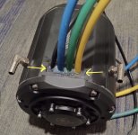
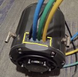
The buck converter is supposed to be good for 96v and 10amps which should be more than enough for the pump. The heat exchanger may end up being too small but I'll start from here. It was less than $20 and should fit nicely on the bottom of the battery in the traditional motorcycle radiator location. To cool the motor I'm planning to wrap it in copper tubing and either put a steel band around the coils with insulation or possibly epoxy over them to keep them from vibrating. I will figure this part out in more detail once I have my selected motor in my hands and can fully consider my options for thermal bonding. I know that there are water cooled motor variations for what I'm looking for but I'm trying to keep costs down where possible. I always like DIY type stuff too, so adding water cooling to an air cooled motor seems like a fun project in and of itself! I'll buy some PC water blocks to cool the mosfets on the controller and buck converter. If I already have a water cooling system in place then why not right? Running copper tubing between the individual 20s packs in my battery should help keep the battery temps in check too I would think. I'm concerned about cold temps as I will be running this all year round to get to work. I may add a heating element to help get the batteries up to temp in certain situations. I could put a heater in the coolant reservoir and run it with a small supplemental battery pack. One that isn't so susceptible to cold temps.
Now for the controller, I'm looking at the Votol controllers because I like the build quality of the boards from what I've seen around the net. The designs seem more straightforward and less compromised for cost cutting measures than some of the other lower-cost controllers. Now I'm probably going to get an earful for this idea, but I'm thinking about buying an em50 and upgrading the power stage myself. I'm no electrical engineer but I've been into this kind of thing since I was a teenager and I have built a couple mosfet SMPS circuits for car audio amplifiers. I know the basics of what will be involved here but I have a couple questions for you guys who may understand these circuits and this controller a little better than I do. Does the controller have an amperage limit that you can't change or can this be changed in the programming software? Let's say my em50 has the capability to handle 200amps electrically, is there anything in the software that will stop me from utilizing it's full potential? I understand that adding mosfets to this controller might not be straightforward because I don't know how much the gate driver circuit can handle. So it may require me to build a gate driver circuit too. Let's say I build a separate output section on it's own board with its own battery connections. Could I use the original output section to drive the gates on my new one? I've never had to use an external gate driver on any of my previous projects and I'm just wondering what is required of the gate driver. Does the gate driver require a special transistor or will the same mosfets I use for the output also be fine for gate drivers?
I would also like some input on my motor selection. Is there anyone out there who has tried both the qs165 and the qs138? Is the 138 worth the extra money? I'm conflicted here because there aren't too many really detailed builds out there with the qs165 but lots with the qs138. At least from what I've been able to find.
Hopefully, I will be working on the frame today or tomorrow and I will have pics of the completed frame soon!
I appreciate any input so don't be afraid to post!
So far, I have obtained two pit bike frames which I intend to base my frame off of. My plan is to cut these apart and combine them to extend the frame. I purchased a titanium 170 from harbor freight and from my first impressions this is a good machine. My previous machine was an older Chicago electric flux core only model. I've been welding on that old machine for close to 10 years and although it is a crappy welder, you can make it work with good prep and lots of practice! Trust me when I say that using a machine like that will make a better welder out of you(but not without much frustration!).
As you can see these frames are pretty small. For what I'm trying to build I will need to extend them. I will use that extra pipe sitting there as an internal sleeve to take some of the strain off the welds. Obviously having a weld joint right in the middle of the frame is not ideal. I chose these frames because they are close to the design I have in mind and I picked them up for a fair price. My Intention is to cut a cheap bicycle frame up and weld the pieces onto the pit bike frames to add pedals. I want this thing to look quasi legal. I need to find a cheap mild steel bike frame to use for this part. Shouldn't be too hard as there are always plenty of huffys and the like for sale(or free) in my area.
For wheels I'd like to use bicycle rims with moped tires. I want the extra rubber from the moped tires for shock absorbtion, durability and traction. I'm not concerned too much about the extra weight. The bike rims should hold up I think. Bicycle rims should be lighter and help offset the extra weight from using heavy bulky tires vs. Using moped or motorcycle rims. What do you guys think about this? Has anyone ever tried to lace a moped hub to a 20" bike rim? What spokes should I use? Would it be better to drill out the bicycle rim to accept the thick moped spokes or should I just use a moped rim too? I'd like some input here. On the front I'll probably use a 22" bmx rim with a thru axle hub for dual discs. Any suggestions for front forks? Are any of the commonly used forks steel so that I could weld on tabs to mount whatever calipers I choose? I don't have much experience in MTB forks so please help me out here.
I plan to water cool the motor and electronics and possibly my battery pack. I have obtained this small water pump, buck converter and a PC water cooling heat exchanger.
The buck converter is supposed to be good for 96v and 10amps which should be more than enough for the pump. The heat exchanger may end up being too small but I'll start from here. It was less than $20 and should fit nicely on the bottom of the battery in the traditional motorcycle radiator location. To cool the motor I'm planning to wrap it in copper tubing and either put a steel band around the coils with insulation or possibly epoxy over them to keep them from vibrating. I will figure this part out in more detail once I have my selected motor in my hands and can fully consider my options for thermal bonding. I know that there are water cooled motor variations for what I'm looking for but I'm trying to keep costs down where possible. I always like DIY type stuff too, so adding water cooling to an air cooled motor seems like a fun project in and of itself! I'll buy some PC water blocks to cool the mosfets on the controller and buck converter. If I already have a water cooling system in place then why not right? Running copper tubing between the individual 20s packs in my battery should help keep the battery temps in check too I would think. I'm concerned about cold temps as I will be running this all year round to get to work. I may add a heating element to help get the batteries up to temp in certain situations. I could put a heater in the coolant reservoir and run it with a small supplemental battery pack. One that isn't so susceptible to cold temps.
Now for the controller, I'm looking at the Votol controllers because I like the build quality of the boards from what I've seen around the net. The designs seem more straightforward and less compromised for cost cutting measures than some of the other lower-cost controllers. Now I'm probably going to get an earful for this idea, but I'm thinking about buying an em50 and upgrading the power stage myself. I'm no electrical engineer but I've been into this kind of thing since I was a teenager and I have built a couple mosfet SMPS circuits for car audio amplifiers. I know the basics of what will be involved here but I have a couple questions for you guys who may understand these circuits and this controller a little better than I do. Does the controller have an amperage limit that you can't change or can this be changed in the programming software? Let's say my em50 has the capability to handle 200amps electrically, is there anything in the software that will stop me from utilizing it's full potential? I understand that adding mosfets to this controller might not be straightforward because I don't know how much the gate driver circuit can handle. So it may require me to build a gate driver circuit too. Let's say I build a separate output section on it's own board with its own battery connections. Could I use the original output section to drive the gates on my new one? I've never had to use an external gate driver on any of my previous projects and I'm just wondering what is required of the gate driver. Does the gate driver require a special transistor or will the same mosfets I use for the output also be fine for gate drivers?
I would also like some input on my motor selection. Is there anyone out there who has tried both the qs165 and the qs138? Is the 138 worth the extra money? I'm conflicted here because there aren't too many really detailed builds out there with the qs165 but lots with the qs138. At least from what I've been able to find.
Hopefully, I will be working on the frame today or tomorrow and I will have pics of the completed frame soon!
I appreciate any input so don't be afraid to post!
 (I haven't)