
jerome_speedy
100 mW
Your project looks excellent ! Smaller than the one I built (6pence resistance spot welder) and only asks for 1 source of energy !
Thanks! Took the time to check your design... The chosen MOSFETs do not have enough avalanche rating yet, even with TVS diodes. These take away only a fraction of the stored inductive energy, there is still a lot of it being dumped into the MOSFET dies. And because their avalanche voltage may have a large production spread, you have to assume that one single of them will take it all. I have estimated 600nH of inductance for my setup, from that you can calculate the energy amount if the current is known.jerome_speedy said:Your project looks excellent ! Smaller than the one I built (6pence resistance spot welder) and only asks for 1 source of energy !
ah ok, maybe he is reading this :wink:jerome_speedy said:When I said "built" I mean just that. I didn't CREATE the spot-welder, another ES member did (pguk)
tatus1969 said:Thanks! Took the time to check your design... The chosen MOSFETs do not have enough avalanche rating yet, even with TVS diodes. These take away only a fraction of the stored inductive energy, there is still a lot of it being dumped into the MOSFET dies. And because their avalanche voltage may have a large production spread, you have to assume that one single of them will take it all. I have estimated 600nH of inductance for my setup, from that you can calculate the energy amount if the current is known.jerome_speedy said:Your project looks excellent ! Smaller than the one I built (6pence resistance spot welder) and only asks for 1 source of energy !
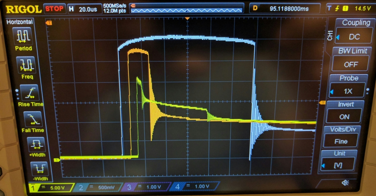
The diode configuration is okay. The problem is a different one, and it is shown in these two pictures from the 6pence thread.jastill said:tatus1969 said:Thanks! Took the time to check your design... The chosen MOSFETs do not have enough avalanche rating yet, even with TVS diodes. These take away only a fraction of the stored inductive energy, there is still a lot of it being dumped into the MOSFET dies. And because their avalanche voltage may have a large production spread, you have to assume that one single of them will take it all. I have estimated 600nH of inductance for my setup, from that you can calculate the energy amount if the current is known.jerome_speedy said:Your project looks excellent ! Smaller than the one I built (6pence resistance spot welder) and only asks for 1 source of energy !
The flyback/freewheel schottky diode should allow the inductive energy to be dissipated amongst the Diodes -- do you not believe that its properly be implemented in the 6pence design?

I sanded them with 1200-grit paper, as I did before with the brass parts as well. It is necessary in both cases, and I expect that the screw clamping force will create a gas tight connection.parabellum said:What are you using to combat the oxide layer of Aluminium bars? ( I mean the flat side, pressed to circuit board)
Anything that permanently keeps the air out will help.spinningmagnets said:Would thermal paste seal the aluminum bar surface from oxidation (after sanding and cleaning it, in preparation for mounting it?)
I just ordered some bottles of chemical nickel plating solvent, it is not very expensive and I will treat all sold aluminum bus bars with that. For aluminium, they sell an "activator" fluid.spinningmagnets said:I have read that if the size of the conductor is not an issue, aluminum works well if it is about 50% larger (in cross-section) than a well-performing copper conductor. As to plating, there are many examples of nickel-plated copper, and now I am curious about the possibility of nickel-plated aluminum?
Anodizing (hard anodizing, at least) is generally an electrically-insulating layer, though, so you'd have to pick a process that doesn't do that (if there is one) if you're anodizing to prevent oxidation of the electrical connections themselves.Hillhater said:Anti corrosion for aluminium is commonly done by "Anodising" the part..... A simple process that can also result in those pretty colors you see on many alloy parts !
Of course I've ordered a copy of the case that I designed :wink: If it fits well, I'll publish the data and also offer it in my store. I don't have a printer myself, but access to a very reasonably priced seller.mxer said:I'd like to see the 3D printed case, has anyone printed one yet?
tatus, I bet you'd like to see your hard work refined in a neat casing. I'm trying to think who has one local to me would be great to see.
I only use FreeCAD for file conversions, as many vendors and other public sources will give you STEP files, and my preferred tool Sketchup doesn't suppor thatspinningmagnets said:I am trying to learn FreeCAD for things just like this. If I can stumble through it, maybe I can post the file on thingiverse, so anyone can order one from a 3D printing service.
I am sure there are hobbyist project boxes that will work, but its nice to have one that is as small as possible, and fits to board perfectly.
Boxes seem to be the easiest starter project to learn.
I'll test first how the behavior is when force / tension is applied, and deliver them with this treatment only when that doesn't show any cracks.fechter said:If you have a bolted connection with enough pressure, aluminum will hold up fine with no plating. I've seen nickel plated aluminum before. The plating peels off pretty easy.

Your original post made me smile, no reason to edit that :wink: And sorry, no pills, just fun and dedication to doing something useful 8)macribs said:Oh man this is nice work. Really impressed.
I don't think I ever seen a more dedicated and rapid developer here on ES. The work you put in, the changes made to hardware as well as changing the firmware all in the span of a summer. And you kept this thread updated like I never seen before. All this while waiting for parts, getting up your website and a webshop.