Making an extension cable to my PAS-sensor

Cyclomania

10 kW
Joined
May 22, 2022
Messages
517
Location
Northern Europe
So, I have an existing PAS-sensor on one of my bikes. I don't want to change the whole PAS-sensor. But instead have an extension cable so I can change between controllers.

Now, I am going to change controller in a little while so I need to create an extension cable from my Julet connection going from the PAS sensor on the bike to my new controller.

The new controller has a CSC pas connection. Therefore I need an extension cable between the controller connection and the Julet connection from the PAS-sensor. Julet on the PAS-end and CSC in the other end.

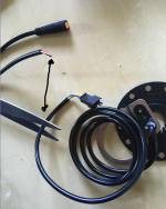
Since I haven't found a good cable for this purpose on ALI or Ebay my plan is to cut off a bit of cable with connection, from one of my other PAS-sensors that I bought, compatible with CSC, and solder it onto another cable I have which is compatible with Julet in one side. See pictures.

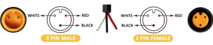
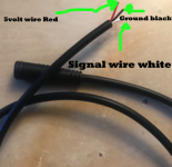
Now, as you can see from the picture, the cables that are going out of the Julet on the no-connection-side does have different colors from the connector that I am going to try to cut of and solder on there. Red, white and black from the Julet cable. And Blue, yellow and red in the CSC-connector.

Therefore, I am not sure which color should be soldered on and put where, to get them in the right order. Could anyone come up with an idea for how to figure this out?

Thanks
 

Attachments

  • Skärmavbild 2022-10-19 kl. 16.29.47.png
    Skärmavbild 2022-10-19 kl. 16.29.47.png
    2.1 MB · Views: 313
With the old controller connected to the PAS sensor, and powered on, set your meter to volts and measure between the controller ground and each of the three wires of the Julet connector in order to identify the 5V wire.

Next, switch the meter to ohms and measure between the controller ground and the two other wires on the Julet. If you get 0 ohms, that's the ground wire. The remaining wire is the signal wire.

On the new extension, red is likely 5V, black is likely ground, and white is likely the signal wire, so match them up before soldering. If you want to be extra sure, you could go through a similar exercise with the new controller before your final soldering.
 
E-HP said:
With the old controller connected to the PAS sensor, and powered on, set your meter to volts and measure between the controller ground and each of the three wires of the Julet connector in order to identify the 5V wire.

Hmm could I do this without the motor connected? It should be okay, right? As long as the battery is plugged into the old controller it should power up right?

Thing is the motor is at the time of writing not working. Since I burned something in there or something.

So I have switched controller and motor on this bike but the old controller is still on the bike and can be plugged in quite simply to the battery.

E-HP said:
With the old controller connected to the PAS sensor, and powered on, set your meter to volts and measure between the controller ground and each of the three wires of the Julet connector in order to identify the 5V wire.

You mean when the PAS-sensor is disconnected from the controller right? And then I measure the voltage on the three cables from the controller end right? To identify what is what.
 
E-driver_ said:
Hmm could I do this without the motor connected? It should be okay, right? As long as the battery is plugged into the old controller it should power up right?

Thing is the motor is at the time of writing not working. Since I burned something in there or something.

So I have switched controller and motor on this bike but the old controller is still on the bike and can be plugged in quite simply to the battery.
please ignore my post to be safe. i never mentioned anything about a motor, so your translator may be not working correctly. don't want to fry something.
 
E-HP said:
E-driver_ said:
Hmm could I do this without the motor connected? It should be okay, right? As long as the battery is plugged into the old controller it should power up right?

Thing is the motor is at the time of writing not working. Since I burned something in there or something.

So I have switched controller and motor on this bike but the old controller is still on the bike and can be plugged in quite simply to the battery.
please ignore my post to be safe. i never mentioned anything about a motor, so your translator may be not working correctly. don't want to fry something.

No, I am writing and reading in english. I know what you mean I think. But I don't need the motor to be connected I believe. Since the battery is connected and I am going to watch the wires with a multimeter. Right?

I don't see this as advice so you can give me tips. Also, I think it is safe to give me tips since I am not in your jurisdiction anyway. It would be another thing if you were in Scandinavia I believe.

What you meant is that with a connected battery and controller you could watch the voltages going out of the three holes, from the Julet controller, and in that way locate which wire is which. Right?
 
I have seen a map of how it "should" be from one of the suppliers from Aliekspress. They send me the above map over which cable is who.

Which leads me to believe that the open end wire should be like the drawn picture below. Please let me know if this is not logical.
 

Attachments

  • Skärmavbild 2022-10-28 kl. 16.55.40.png
    Skärmavbild 2022-10-28 kl. 16.55.40.png
    427.7 KB · Views: 183
  • Skärmavbild 2022-10-28 kl. 16.58.18.png
    Skärmavbild 2022-10-28 kl. 16.58.18.png
    292.7 KB · Views: 183
I guess I could also try it all out with one of the small connectors looking like the ones below, to see if the PAS-sensor activates, right?

Or do you think I could short circuit something or something like that, if I put the wrong wire to the wrong partner? Or would this short circuit be so small that it would have no effect on the rest of the system?

I mean one of these connectors for testing(before I solder it on):
 

Attachments

  • Skärmavbild 2022-10-28 kl. 17.19.38.png
    Skärmavbild 2022-10-28 kl. 17.19.38.png
    360.2 KB · Views: 182
Ok, it worked. I soldered on the wires and made it work.

Now, I am trying to make the best installation on the sw900 display.

Could anyone tell me about this one:

"P11 PAS sensitivity. Range: 1-24"

Does this mean that the higher end, closer to 24, kicks in the PAS-sensor earlier? Or does it kick in earlier if it is closer to 0?

Did not quite understand that setting.

Also P7 is a weird one: "P07 Speed measuring magnet. Range: 1-100".
Mine is set to 46. Any idea what it means or if I should alter it? My bike is 29 wheels, 48 volt. Motor 1000watt.
 
Back
Top