
You are using an out of date browser. It may not display this or other websites correctly.
You should upgrade or use an alternative browser.
You should upgrade or use an alternative browser.
Meanwell clone- AD488.3-400W power supply mods
- Thread starter fechter
- Start date
mighty82 said:Is there an easy way of terminating the charge when it's finished with the CC phase or at a specific voltage. That's the only problem I have with charging my Lifepo4 pack. During CV phase one or more cells will start overcharging if i'm not babysitting it.
Not really. There are plenty of complicated ways to do it.
One approach is to get a meter like this one:

https://www.ebay.com/itm/Programmable-90V-100A-Combo-Meter-Volt-Amp-Power-Ah-Hour-Battery-Capacity-Tester/170841787761?epid=1763225329&hash=item27c6f6cd71:g:We8AAOSw42JWD-gb
Combines many functions in one, Dual display
Voltage (V), Power (W)
Current (A), Ampere-hour (Ah)
Working Hours (H)
Alarm control when over/under limit (Built-in Buzzer)
By turning External device Relay on and off, it can control external devices, such cut off Power Input
[OVP] Over Voltage protection
[LOP] Low Voltage protection
[OCP] Over Current protection
[OAH] Over Charge protection
[OPP] Over Power protection
[OFT] Over Time protection
Expandable with ext'l Shunt and Relay
It can be programmed to turn off a relay when any of the alarm conditions are exceeded. This particular model says it can only work up to 40v without using a separate power supply for the display. I have one at home that is similar but works up to 80v and has the relay built in. I can't seem to find any like that today, but I'm sure they are around.
flippy
1 MW
- Joined
- Aug 12, 2015
- Messages
- 2,351
better one:
https://www.aliexpress.com/item/RD-DPS8005-programmable-constant-voltage-current-Step-down-power-supply-module-Voltmeter-Ammeter-buck-converter-80V/32849962454.html?spm=a2g0s.9042311.0.0.2cf64c4dlhvc1b
also much higher quality and you can hook it up to a pc or phone for control and stats readout.
if you get 2 you can use this supply:
https://www.aliexpress.com/item/Single-Output-DC-power-supply-Switching-90V-11-1A-1000W-Driver-Transformer-110V-220V-AC-to/32846889270.html?spm=a2g0s.9042311.0.0.2cf64c4dlhvc1b
and have 2 independent chargers capable of being combined to a single 80V 10A charger.
Yes, those look better. I have a very similar one on my Meanwell but it doesn't have the software or alarm features. Accuracy was not so good but you can tweak it to get close enough.
brianjonesphoto
10 µW
- Joined
- Jun 14, 2018
- Messages
- 5
Am I understanding this correctly you can purchase one of these clone power supplies and hook up one of these DPS8005 controllers and you do not have to do any mods?
flippy
1 MW
- Joined
- Aug 12, 2015
- Messages
- 2,351
yes.
i got the 90V 10A 1000W power supply and 2 DPS units (rated up to 5A@87V) so i can use 2 DPS units at full power from 1v to 87V at 5A. but note the ground is common so you can't series the outputs to get higher voltages. you need 2 separate supplies for that to work. but you can parralel them to get 10 amps.
i got the 90V 10A 1000W power supply and 2 DPS units (rated up to 5A@87V) so i can use 2 DPS units at full power from 1v to 87V at 5A. but note the ground is common so you can't series the outputs to get higher voltages. you need 2 separate supplies for that to work. but you can parralel them to get 10 amps.
vicens
100 W
What do you think of this power supply?
https://s.click.aliexpress.com/e/VmWnvR3
Is to put 3 in series, and charge a lithium battery from 38S to 158v maximum voltage.
Would it be possible to regulate the load current limit? It looks like a clone of mean well.
I would like to regulate the current limit to 13A.
https://s.click.aliexpress.com/e/VmWnvR3
Is to put 3 in series, and charge a lithium battery from 38S to 158v maximum voltage.
Would it be possible to regulate the load current limit? It looks like a clone of mean well.
I would like to regulate the current limit to 13A.
Hard to tell from the ad. Really need to see the inside. Most likely there is a way to modify it.
eee291
100 kW
https://www.amazon.de/gp/product/B07DWVMBPY/ref=ox_sc_saved_title_3?smid=A38I4T5NBLJJJ3&psc=1
This one works great, I don't know if Amazon DE/Seller ships to Spain though
This one works great, I don't know if Amazon DE/Seller ships to Spain though
SlowCo
1 MW
Great thread! I just started to look into these power supplies thinking of charging my battery pack with one. Seeing these mods I think I'll order one soon from AliExpress to see if I can get it to work on my 16S LiFePo4 pack.
vicens
100 W
fechter said:Hard to tell from the ad. Really need to see the inside. Most likely there is a way to modify it.
I have been searching. In the comments appear photos and description of the components.
It seems that it is the same power supply that is:
https://radiokot.ru/forum/viewtopic.php?f=11&t=158470
The back is this:

It has 50V output capacitor. Should carry 63V.
It has a LD7575 pwm controller
https://lib.chipdip.ru/923/DOC000923326.pdf
I add some more pictures. I think it's not enough to check the scheme and see if it's limiting in current.

Do you think it would be good to buy? Or better of another brand of better quality.
I have no problem adding resistances. nor change capacitors. Nor make measurements.
vicens
100 W
eee291 said:https://www.amazon.de/gp/product/B07DWVMBPY/ref=ox_sc_saved_title_3?smid=A38I4T5NBLJJJ3&psc=1
This one works great, I don't know if Amazon DE/Seller ships to Spain though
Yes, I can buy in Spain.
That model is with adjustment wheels. More expensive than the model without adjustment. I will look at the normal model.
I would like to buy the 800 or 1000W model. I look if the seller has the one I like for 1000W.
The catalog is very limited, it only has this one.
https://www.amazon.de/Energieversorgung-Spannungsanzeige-Yeeco-Spannungswandler-Computer-Projekt/dp/B07DWVBTR7/ref=sr_1_96?m=A38I4T5NBLJJJ3&s=merchant-items&ie=UTF8&qid=1546133328&sr=1-96
The one in the picture does NOT look like it has secondary side current limiting, so probably not a choice for a battery charger unless a limiter circuit is added.
The last one in the link has a nice voltage adjustment, but can't tell about current limiting.
The ones made as LED drivers typically work well as battery chargers. They can run at the limit for a long time without overheating.
The last one in the link has a nice voltage adjustment, but can't tell about current limiting.
The ones made as LED drivers typically work well as battery chargers. They can run at the limit for a long time without overheating.
eee291
100 kW
https://www.aliexpress.com/item/Switching-Power-Supply-0-48V-0-20A-1000W-Digital-Display-Voltage-and-Current-Adjustable-Regulated-Power/32869363513.html?spm=a2g0s.8937460.0.0.378c2e0eJCLC92
This one also goes from 0-51V and 0-21A
It is pretty expensive though.
This one also goes from 0-51V and 0-21A
It is pretty expensive though.
DrkAngel
1 GW
US Amazon available:
480w 48V 10A - $133
480w 48V 10A - $133
eee291
100 kW
https://www.aliexpress.com/item/Current-limiting-adjustable-voltage-and-current-regulator-480W-switching-power-supply-0-24V20A-0-48V10A-0/32825551332.html?spm=2114.search0104.3.9.cb9a1799YeQt7K&ws_ab_test=searchweb0_0,searchweb201602_3_10065_10068_10547_319_317_10548_10696_10084_453_454_10083_10618_10304_10307_10820_10821_538_537_10302_536_10059_10884_10887_100031_321_322_10103,searchweb201603_6,ppcSwitch_0&algo_expid=4dc4afd0-ce68-422d-86e3-56db8d190401-1&algo_pvid=4dc4afd0-ce68-422d-86e3-56db8d190401
Quite a bit cheaper from China
Quite a bit cheaper from China
bobmutch
100 W
0-120V 0-4A CC/CV Switching mode Power supply $70 shipping to USA included.
0-80V 0-6A CC/CV Switching mode Power supply $70 shipping to USA included.
These looks the same but a bit less expensive. Has anyone ordered there?
https://www.aliexpress.com/item/480W-digital-display-switching-power-supply-Adjustable-voltage-Current-limit-0-24V-36V-48V-60v-80V/32947648436.html

0-80V 0-6A CC/CV Switching mode Power supply $70 shipping to USA included.
These looks the same but a bit less expensive. Has anyone ordered there?
https://www.aliexpress.com/item/480W-digital-display-switching-power-supply-Adjustable-voltage-Current-limit-0-24V-36V-48V-60v-80V/32947648436.html
bobmutch
100 W
eee291 said:https://www.amazon.de/gp/product/B07DWR6RNK/ref=?smid=A38I4T5NBLJJJ3
This one works great, I don't know if Amazon DE/Seller ships to Spain though
This looks the same as the PSU at the link below
https://www.aliexpress.com/item/480W-digital-display-switching-power-supply-Adjustable-voltage-Current-limit-0-24V-36V-48V-60v-80V/32947648436.html
Did you have good experience with this one?
https://www.amazon.de/gp/product/B07DWR6RNK/ref=?smid=A38I4T5NBLJJJ3
eee291
100 kW
Yes its been pretty good so far. I even accidentally reverse connected a 12V lifepo4 battery without damaging it.
It did produce a spark though :lol:
As you can imagine the built-in LCD is just for rough tuning the voltage. I suggest keeping a good multimeter nearby.
It did produce a spark though :lol:
As you can imagine the built-in LCD is just for rough tuning the voltage. I suggest keeping a good multimeter nearby.
bobmutch
100 W
I don't like the above PSU any more, this below is batship.
What is the crazy stuff they want you to do below? Like you have to plug this adjust current plug into the PSU then set you current and shut the PSU off and then remove the plug then turn it on again. Thanks batship.
Operational use
(How to limit current) to adjust current?
1. Operate in the case of power failure, pull the small pull switch in the lower left corner to the current regulating gear
2. Pull out (dedicated current regulating insert) to the 2nd and 3rd ports of the wiring port, loosen the port screw with a screwdriver, and tighten with a screwdriver (at this time, connect to the listed power), and then connect The voltage of the meter shows 0.00V, and the current shows the current current parameter. At this time, the power supply will emit a small current.
3. On the right side (adjust current knob), you can adjust the desired current limit parameter, and display the current parameter synchronously with the digital display. 0-21A/0-16A/0-11A/0-6.5A can be adjusted in the whole process.
4. Remove the (special adjustment current plug) and insert it back into the original insert card holder. After removing the digital display, the voltage is about 0.90V, and the current is 0.00A.
5. Pull the pull switch in the lower left corner to the right to open the "open (use)" position.
6. The current power supply is in the parameter value of the current limit. The power supply is adjusted to a few V (the digital display shows the output voltage in real time), the current does not change, and the current reaches the current limit of 95% of the current limiting parameter. Overload protection
7. The current parameter displayed by the digital display at this time is the current value of the device load, and the load current is monitored in real time.
View attachment 1
bobmutch
100 W
mighty82 said:That's the only problem I have with charging my Lifepo4 pack. During CV phase one or more cells will start overcharging if i'm not babysitting it.
What the configuration of your LiFePO4 pack? volts? Ah? kind of cells? BMS?
What kind of a charger are you using?
mighty82 said:Is there an easy way of terminating the charge when it's finished with the CC phase or at a specific voltage.
If you are doing a bulk charge to a non-BMS'ed battery pack you could monitor the cells with a 8S voltage monitoring unit. You can set a HVC and it will activate an auto alarm.
Sorry for resurrecting an old thread but I need some help troubleshooting my S-400-48 Meanwell clone which is almost identical to the ones in this thread. I bought two of these power supplies to charge my 24s LiPo pack. I wanted to reduce the current limit to 5A like the rest of you. The controller on the board is a TL494CN and I used the datasheet to figure out that the resistor I need to change is R33 (500ohm stock). I replaced R33 with a 500ohm pot on one of the power supplies and tested current limiting with a power resistor and it worked as expected.
I messed up while replicating this mod on the second unit and turned it on with a bad solder joint on one of the pot terminals. To make things worse, I damaged the trace around one of the R33 terminals which leads to what I think is the current sense shunt. This caused the two FETs (2SC3320) to blow, probably due to the current limit now being theoretically infinite.
I replaced the FETs and turned the power supply back on. With no load connected, I measured 43V across the output terminals. However, when I connected wires to the output terminals (still no load), the FETs blew again. The fuse on the board is okay but the circuit breaker at home tripped on both occasions. I tested all diodes on the board and they seem to be fine. Any ideas what could be wrong? I'm attaching pictures of the board. This is my first time posting here so apologies if I'm not clear enough.
Attachments
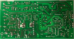
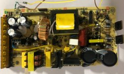
It can get pretty hard to troubleshoot when it starts blowing parts. I have only had partial success repairing supplies that have blown FETs. Check all diodes with a meter and look for shorts. The TL494 would be suspect as well as the LM395. Once a FET blows it can take out other parts along the path. Sometimes it's better to just get a new supply.
Similar threads
- Replies
- 5
- Views
- 901
- Replies
- 128
- Views
- 12,522
- Replies
- 4
- Views
- 1,209