Miles' 90mm inrunner build thread

Miles said:
Yes, Wye termination.

I presume so. You get different values as you vary the load........
I ask this because a stator with WYE is inductance in series. But delta is in parallel to 2x the inductance of one phase.
Also the motors I measured the stator on the bench out of the magnet ring were about 2x what they were once in the magnetic field.
 
Thanks Arlo
Arlo1 said:
I ask this because a stator with WYE is inductance in series. But delta is in parallel to 2x the inductance of one phase.
Sure, understood. I'd never use a Delta termination.

Arlo1 said:
Also the motors I measured the stator on the bench out of the magnet ring were about 2x what they were once in the magnetic field.
That makes sense. The simulation shows induction decreasing as flux increases.
 
That's simply because of the shape of the BH-curve. Inductance is proportional to the slope (derivate) of the curve. If the teeth are fully saturated, the slope is u0, which means the winding has the same inductance as if it was wound in air. My Emetor simulations of the Colossus showed almost fully saturated teeth at no load. That can't be a good design, for many reasons. That's why I said earlier that a "properly designed" designed motor shouldn't have problems with too low inductance. I believe Miles motor is designed to have about 1.7T in the teeth, which means there is still a nice slope in the BH curve at no load, and low-medium loads.

EDIT: The Sura electric steels saturates at about 2T, so 1.7T is still with a margin to saturation. The curve attached to this post shows a simpler electrical steel which saturates at about 1.6T.

BH_iron[1].png
 
Thanks bearing. I'm slowly getting a better grasp on this stuff... :) The present plan is to use Hiperco laminations, so flux density is a bit higher.

It's interesting to give attention to the development and effects of core saturation. Obviously, if all of the teeth are fully saturated, that's the "end of the line". Up to that point, though, there's a relative difference.

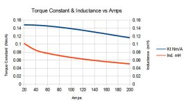
In terms of the effects, in the simulations of my design, Kt is almost flat from peak eta torque (20A) to twice that value (40A) and then falls away gently. You never reach the "cliff".
 

Attachments

  • Kt-&-Ind.-vs-Amps.jpg
    Kt-&-Ind.-vs-Amps.jpg
    37 KB · Views: 1,385
If you need any machining done, shoot me some dimensioned cad drawings. I have a surplus of 4" and 6" 6061 T6 round stock, as well as some 1" 4340 shaft steel. You have helped me so much with my motor design questions, that I would be more than happy to help expedite the process for you however I can. :mrgreen:
 
Thanks for the kind offer, Farfle :D I'll bear it in mind.

Having the laminated rotor, all that's left to machine, really, is the case. I have the tubing for the can, which hardly needs more than truing/skimming on the lathe. Then there's the endcaps to turn from solid 3.75" bar, which I also have. No excuses there :mrgreen:
 
Miles said:
Thanks for the kind offer, Farfle :D I'll bear it in mind.

Having the laminated rotor, all that's left to machine, really, is the case. I have the tubing for the can, which hardly needs more than truing/skimming on the lathe. Then there's the endcaps to turn from solid 3.75" bar, which I also have. No excuses there :mrgreen:

looks like you have it handled lol, That offer for a nice machined 4340 shaft still stands though :D
 
This will give a better picture of what's going on...

[pre]N45 magnets
No load 0.56A - phase to phase inductance 1.7253 mH
Peak eta 30A - phase to phase inductance 0.0913 mH

N35 nagnets
0.56A - phase to phase inductance 1.5090 mH

Phase to phase resistance 0.03054 Ohms[/pre]
 
You are at over 1mH now? Different wind?
So the N35 had less inductance. I would have assumed the opposite.
 
bearing said:
You are at over 1mH now? Different wind?
So the N35 had less inductance. I would have assumed the opposite.
Same wind but at no load current rather than 30A...... I've always given the nominal inductance figure for peak eta current. Does that not make sense?

I'm not clear why lowering the field reduces the inductance, either. Floating voltage, everything else, apart from the magnet strength, was kept constant.
 
Ahh, now I see. I misread the second line as 0.9mH.

The reason for the dropped inductance with N35 may be because the BH curve is S-shaped. I'm not sure if the no load inductance values can be trusted though, since there is such a big difference. Doesn't seem right.
 
Part way through this paper on motor parameters.
"Design Criteria for High-Efficiency SPM Synchronous Motors" Nicola Bianchi, Member, IEEE, Silverio Bolognani, Member, IEEE, and Paolo Frare

pdf download https://www.google.com/url?sa=t&rct...U25p_MWzGtSq2NJu_--TaWw&bvm=bv.60157871,d.eW0

Lots of dimensional relationships evaluated and fill factors explained in good depth. Getting lost a bit, but see it much more clearly now. Will need to study much more on it, but wanted to share.
 
Back
Top