Molicel P42A, Sony/Murata US18650VTC5D in 14s5p battery packs sounds like a good deal?

floydr

100 W
Joined
Jan 30, 2022
Messages
168
I also ordered some of these packs, 6 to be exact, was just too good of a deal to pass up, $1.4 per p42a. These also, according to some people whove already received the packs, test up to the rated capacity, right between 4100 and 4200mAh per cell at 1 amp discharge, really amazing!

They also appear to be really easy to tear apart which is a positive. Ive got no information on the bms though seems to be completely proprietary.

Also for anyone curious these appear to have come from a mech robot suit type thing called the "XO" and if I had to guess these packs were being liquidated after Sarcos rebranded to Palladyne AI.
 
I received my order today,
these packs are very very very long and bulky, as is, they are NOT usable.

My sarcos pack came in with what appears to be a dead BMS (hibernating?),
when I press the switch, I do not get any light.
Checking each bank I found them to be at 3.55 to 3.53 v

I have not figured out how open it up further to a peek at the bottom and the pack.

keyword: sarcos, robot Molicel 21700
 

Attachments

  • batt_negative_sarcos.jpg
    batt_negative_sarcos.jpg
    185.7 KB · Views: 18
  • 5cables_1.jpg
    5cables_1.jpg
    211.3 KB · Views: 18
  • no light.jpg
    no light.jpg
    130.2 KB · Views: 18
The bmses appear to be completely proprietary and I would assume that without a decent amount of reverse engineering theyre just worth their weight in scarp. I doubt that that button is for enabling discharge, it is more likely a 'clear state' or something along those lines used for testing or validation. Would be more likely that the pins circled in red are used for enabling/disabling discharge or are some other type of communication between the bms and the system they were attached to. Could be as simple as shorting one of them to ground or as complicated as a canbus or a uart protocol. Hell it could be some completely proprietary protocol too...
1714419594972.png

Also an update on my order, ended up ordering another two packs, totalling eight now, and tracking lables have been created for both but neither have had a package dropped off yet, fingers crossed theyll arrive sometime later this week!
 
I received my order today,
these packs are very very very long and bulky, as is, they are NOT usable.

My sarcos pack came in with what appears to be a dead BMS (hibernating?),
when I press the switch, I do not get any light.
Checking each bank I found them to be at 3.55 to 3.53 v

I have not figured out how open it up further to a peek at the bottom and the pack.

keyword: sarcos, robot Molicel 21700


Looks great I want it some but I have three batteries in the garage I'm not using right now.
 
Yeah it's my kind of battery I have those in a NESE kit in a MTB just needs the handle bar stuff.
If I need a 80amp battery I build a 160a battery for I think lower I believe resistance and able to pass the electrons back and forth easier and should last longer without the load or the heat in let's say 100 amp battery for an 80 amp controller.
Just about hanging out in this thread maybe Floyd wouldn't mind if we step all over his thread about batteries. ?
 
Hang out as much as you like. I received my 2 packs today too. I have had the cover/handle off looked at the BMS, decided I will wait till tomorrow before I dive into the tear down/ attempting to get the BMS to work.
later floyd
 
I bought one for $99.99 on Saturday. Today the battery is $110, so they must be selling well.
 
I bought one for $99.99 on Saturday. Today the battery is $110, so they must be selling well.
Yeah very...they sold ~500 units just on friday, also for anyone curious as of right now theres 192 molicell packs left in stock and 17 sonys, will probably last another day or two for anyone else interested in buying one.
 
I removed all the screw from the sarco battery BMS, cut the wires from the pads to the bms, unhooked the three thermistors, only thing still holding the BMS on is a 5 wire connector near the center of the board and the main negative and main positive connections to the BMS. I got the BMS to flex about a 1/4 inch on either end. Might have to cut away the plastic to expose the cells I really don't want to might be the only way unless someone more patient/smarter than me figures out a way to activate the BMS/ remove the BMS without destroying the case. maybe @gobi had better luck than I am having.
Later floyd
 
Floyd,
I was procrastinating while you took a stab at it :D

I really have on use for the batt/cells now, just bought it cuz it was cool, I want to be able to use it as is if possible.
Yes, we should be able to reverse engineer the bms.

My electronics chi is very low due to a decade of changing diapers and related tasks of being a single dad, I am not very well experienced in recognizing surface mounted components off the batt. I usually look up the chip number and read the spec and figure out what it does.

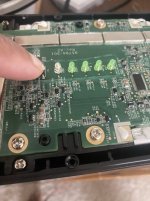
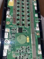
Problem 1 - Looks like Sarcos put some kinda paint/epoxy of the chip surface to HIDE the numbers before they applied conformal coating. The conformal coating looks like it was hand applied, makes sense as these are sample units for their prototype probably.

My girls have a UV flash light and a USB 40x microscope, would that help in reading the numbers?


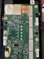
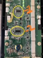
I see 2 large chips which are probably the controller chips, from reading on EEVBLOG, here and other most BMS now use a controller chip which voltage sense and puts the bms in sleep mode and other functions that can be programmed.

Question - Can anyone identify the 2 rectangular chips marked Items 1 and 2 in the pics below?
TI MCUs are square shaped, from what I have seen in other battery bms with advanced features.
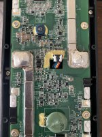
Switching + pole -
3 sets of 8 pin mosfets are used to switch the positive pole.
why 8 pin mosfets?

1st bank is switch via a NTC, I am guessing that is the thermal protection bank

2nd ? (witch craft?)

3rd bank ? (batt/cell voltage switched?)


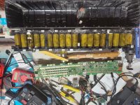
Physical construction:
Looks like there is some GLUE at the bottom holding the batt module to the bottom of the case, I too took off all outer screws once the I took off the top.

I was expecting the batts unit to drop off the case once I inverted it, but no dice,

I used 2 screw drivers to pry at the edges and I got the negative end to come up few mills and heard a loud crack.

Charging:
I did not see any charging ports, so I guessing the discharge ports are used to charge these.

5 pin connector:
My 5 pin connector is covered in some yellow glue, pretty nasty hard stuff, I tried to scrape it off with my manly nails, no dice.


Request: Floyd, if you are going destroy the bms, could you do me a fav and scrape off the glue around the 5 pin connector and take a pic pls.
 
what component are these?
 

Attachments

  • sarcos_mcus_1.jpg
    sarcos_mcus_1.jpg
    298.1 KB · Views: 9
8 pin mosfets, 3 banks of them
 

Attachments

  • sarcos_positive_pole_switching_1.jpg
    sarcos_positive_pole_switching_1.jpg
    259.6 KB · Views: 4
I will try to get back to the battery later this week. i will take some pics as I remove the BMS. Including the 5 pin connector
Request: Floyd, if you are going destroy the bms, could you do me a fav and scrape off the glue around the 5 pin connector and take a pic pls.
I figure the BMS is pretty much non repairable now. I have some glasses i bought to do some surface mount work, I will see if I can figure out what the two rectangular ic chips are, if I can read the part numbers.

Later floyd
 
If you have a poweful soldering iron(I don't), you can desolder the corners and the two power lines (in the middle). I used a Dremel and drill to remove BMS. Desoldering or removing the powerlines will allow you to remove the case and preserve the BMS (after removing screws and 5 pin connector).
'dale
 

Attachments

  • 20240503_185532.jpg
    20240503_185532.jpg
    4 MB · Views: 19
Last edited:
If you have a poweful soldering iron(I don't), you can desolder the corners and the two power lines (in the middle). I used a Dremel and drill to remove BMS. Desoldering or removing the powerlines will allow you to remove the case and preserve the BMS (after removing screws and 5 pin connector).
'dale
Good work,
So the 2 solders in the middle hold the pack down,
Can you please post a pic of the profile of the batt (sideways view) and a close of the 5 pin connector part of the BMS (close up)


3 bank of 8 pin mosfets:
Bank 1 and 3 are pass through and have nearly 0 ohm resistance,
Bank 2 needs to be switched on.
 
They're now at $120 from BH. That's up $20 from the original price of $100. I now believe that I should of bought several more.
I'll receive one of them tomorrow and see first hand what the size and weight is, and see what bike I can fit it to.

I hope someone can figure out the BMS. Sarcos has left robotics and is now into AI. So, we reap the rewards of their failed investments. Maybe some ex-EE from Sarcos can visit us and explain the ins-and-outs of this battery.
A 100a 48v battery is new territory for me, and I'm now following the 1500w Leaf motor thread.
 
Well, I received the battery today. For a $100 plus shipping it is truly a most impressive battery, though, too big for any donor bike I currently have. If I could get a Noslisu cargo trike, I would put that and a 1500w Leaf hub motor on it. If I had another one of them I might be tempted to resurrect my plan to convert my Grom to electric. But the fuel sipping Grom runs too well at the moment to experiment with.
So, I have this beautiful battery, and as of yet, no application.
 
1715033113486.png
5 pin harness. Seems like the order is reversed
This maps to the connectors as follows: ignore the + and -.1715032802884.png
And the best pic I could get for the chips was: need a decent microscope.
1715033539155.png
Good luck on hacking this and keep us posted!
I am almost tempted to try it myself, but I FUBAR'ed tthe plug:
1715033663155.png
'dale
 

Attachments

  • 1715033020853.png
    1715033020853.png
    53.7 KB · Views: 3
  • 1715032636276.png
    1715032636276.png
    852.2 KB · Views: 3
I opened the case of my battery. I like the easy to change 100a fuse:

sarcosBatt.fuse.jpg

What's up with the battery sleeves?

sarcosBatt. slieve.jpg

If someone could figure out how to communicate with the BMS this battery would be incredible, imho.
Maybe, I Robot?
 
Im also curious as to what this silver/grayish material is, seems to be metallic but it isnt conductive and reminds me of a cross between fibreboard and thick cardstock, am most likely going to reuse it for the pack Ill be building from these cells as it really is quite nice.20240506_175656.jpg
What's up with the battery sleeves?
They are what seems to be something similar to fishpaper wrapped in kapton tape, theyre just loosely on there and only cover the cell in the space between the cell holders, wonder why they didnt just leave them unwrapped as theres easily enough clearance to not risk shorting them, its an interesting thing but I dont know if its worth reusing...
 
View attachment 352307
5 pin harness. Seems like the order is reversed
This maps to the connectors as follows: ignore the + and -.View attachment 352305
And the best pic I could get for the chips was: need a decent microscope.
View attachment 352308
Good luck on hacking this and keep us posted!
I am almost tempted to try it myself, but I FUBAR'ed tthe plug:
View attachment 352309
'dale
Thanks a bunch, I guessed that it was a TI chip counting the 44 pins,

https://www.tij.co.jp/lit/ug/tidues4/tidues4.pdf


2.3.4 Wake-up Circuit DesignWhen the battery pack is first time powered on or with very low battery voltage, the system enters the shipmode and the entire system, except for BQ76940, powers off to save power. In this mode, the BQ76940device monitors the wake up command. This design gives two wake up methods, the first method isthrough a button that generates a wake-up signal on TS1 pin. The second method detects if the chargerattached with the circuit shown in Figure 3. When a right charge is attached, Q15 is turned on and pullTS1 high, and because of C20 and C18, Q15 is turned off, generating a wake-up signal on TS1 pin. Wakesignal is from the MCU and can also wake up the BQ76940 from shutdown mode.
 
What was the cell voltages. Were they left at storage levels ... 3.43 volt.

I bought one. Haven't opened the cardboard box. It sure is heavy.
Mine came it in at 3.53 volts,
I charged it to 3.75v per cell
 
Last edited:
Back
Top