Motor hall sensor replacement

dcuste

10 mW
Joined
Aug 2, 2019
Messages
20
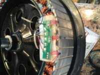
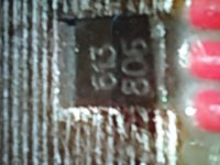
I have a bad hall sensor in my 1500w motor. I took a bunch of measurements and there is no question, it is a bad sensor. The other two are fine. The problem is finding a replacement sensor. It has a number on it of 613805 or may be 613806. Can't say for sure. I know the other good sensors latch when a South pole and release with the North pole. I think that makes it bipolar. The small face of the sensor measures 3mmX2mm. I haven't pulled the sensor out, so I can't say what the other measurements are.

Looking on digikey, they list about 200 sensors that meet that description. But they all have different other specs. None of them have a similar number. I would like to get an exact replacement so I don't have to replace all three sensors. I wrote to what I think is the motor manufacturer (NBPower), but I doubt they will respond.


Does anybody know how I can solve this sensor selection problem?
15667465202451587973686.jpg
 
Almost certainly it uses the same hall sensors that are listed in most of the many threads about hall sensors on teh forum, the Honeywell SS411A type. That's what I've used during all replacements I've ever done.

https://endless-sphere.com/forums/search.php?keywords=SS411A&terms=all&author=&sc=1&sf=all&sr=posts&sk=t&sd=d&st=0&ch=300&t=0&submit=Search


The numbers on yours are probably just the chinese version of that; only available over there.

There's little reason that it wouldn't work to just replace one, if the other two are workign they wont' stop working becuase one is different. ;)
 
Thanks Amberwolf. They should be here in a few days. I'll let you know if they do the trick.

I have another question. There are six of these small wires coming from the motor. Five are all about the hall sensors. The sixth wire is white and appears to go between the windings and then connects to the black (negative) wire. I'm guessing this is some sort of thermistor to read the winding temperature. Funny thing is, the wire never makes it into the controller. It just ends at the six pin connector. I've read that some bikes measure the motor temperature from the hall sensors. What do you make of this? Does it mean my bike has no motor overheating protection?
 
Few controllers do anything about temperature monitoring. But it's probably a typical 10K NTC type, so you could hook it up to anything that can read that. Some outdoor patio or BBQ thermometers use that type, so you could disconnect the sensor built into the BBQ head unit and wire that one in instead, and if it reads the same as the original BBQ sensor at ambient, it's probably the same (you can verify at higher and lower temps too, using something to heat and cool that area of the motor in a controlled fashion).

If you want the system to automatically lower power based on temperature (or a number of other limiting factors), you can use the Cycle Analyst v3 (it can do other things too). http://ebike.ca Grin Tech


IIRC the Phaserunner (also by Grin Tech) can monitor temperature and respond, but I'm not sure.

High end controllers like Sevcon can do it, but they're a huge PITA to setup (pretty much intended only for OEM use).

I think the Lebowski DIY controller can do it, but you ahve to build it.
 
I checked the new sensor and found the only difference between it ant the old ones that were switching properly is that the new one switches all the way to zero volts were as the old ones will only go to 0.3v when the North pole gets to within about one inch of the face of the sensor. Everything else seems about the same. So I replace just the old sensor that I presumed bad and then tested. Much to my shock, the new sensor is acting just like the bad sensor and only dropping about 3.0v when the North magnet approaches. So I disconnect the output lead to the sensor, and test to prove the voltage does drop to zero. I measure the resistance on the board and find that there is 10meg ohms between positive and the output lead. I don't see a resistor so I'm guessing the board is bad. On the picture, I'm measuring 10 megs between the hole for the lead that's pulled at the bottom of the picture and the middle connection point on the board for the yellow lead wire.

Does anybody know if there is supposed to be a 10 meg ohm resistor or do I have a high resistance short here? 15670343341381587973686.jpg
 
dcuste said:
I checked the new sensor and found the only difference between it ant the old ones that were switching properly is that the new one switches all the way to zero volts were as the old ones will only go to 0.3v when the North pole gets to within about one inch of the face of the sensor.

Is that an open-circuit reading, or with the output connected to the controller?

The controller has pullup resistors inside it that create the "5v" on the output of the hall, as the hall itself only has an open / short-to-ground type output (it doens't output a voltage of it's own).

So when halls are correctly connected to the controller, and all is working right, then when the magnet turns the hall on, it grounds the output to something close to 0v, but it doesn't usually reach all teh wya to zero, can be as high as about a volt.

Whenever the hall is off, the output is no longer grounded, so it rises to whatever the controller's pullup resistor is tied to (usually the 5v line).

If a hall does go up to the supply voltage (or close to it) when off, but won't ground when on, the hall is usually bad (on rare occasions, it's the hall ground wire that's bad, but that usually is the ground wire in the cable out of the motor so they *all* have this failure).


Much to my shock, the new sensor is acting just like the bad sensor and only dropping about 3.0v when the North magnet approaches.
*to* 3.0v, or to about 2v?

I measure the resistance on the board and find that there is 10meg ohms between positive and the output lead.
What do the others read?

There should be a medium resistance (a few kohms) from positive to the output, when it's connected to the controller (and the controller is not powered on).

When it's not connected to the controller, the actual sensor resistance varies between models, but it'll be pretty high, like what you read.
 
Again, thanks for all your help. I didn't explain what I was seeing very well. But from what you pointed out I redid the connections and it appears all is well.

I'm getting my 5v supply from USB 1.55 amp supply. I now have the controller plugged into the rest of the hall wires with just the red and black pins pulled out of the connector. When I first plug in the supply then put a South pole near each and all three voltages read 5v from positive to the hall outputs. I then hit each hall with a North pole and the reads drop to 0.9v each.

What do you think? Am I ready to put it all back together and go for a ride? Do you have a recommendation for what type of epoxy I should use to glue the hall in and glue the board down?
 
The way you are testing the Halls seems somewhat convoluted.
I plug everything together and use the 5V from the controller. If one is using the crappy white Nylon connector, I go in thru the backside w/ my multimeter leads. If the hall connectors are not accessible, I'll stick a pin thru the wire insulation.
Red to blk.-5V
Leave blk. (or whatever the color of your gnd. is) connected- go Pos. lead to one hall lead and rotate motor- should flash 5V. Repete for the other two.
I use JB Weld steel epoxy which seems like what they use at the factory. When dry, it does not conduct and can be filed (Demeled), which is a good thing if you want to do some clean-up.
 
And just a word of advice for anyone else w/ one or more bad Halls and doesn't want to try and match at outlets like Digikey.
The nice folks from Grin (Ebike CA) sell Hall sensors (Also some PCB's). I imagine one could just tell them what motor one has and they could supply them.
That's what they did for me.
They can go in a letter envelope, so not much $ to send.
 
Back
Top