My first EV conversion: '69 Honda CA160 "Baby Dream"

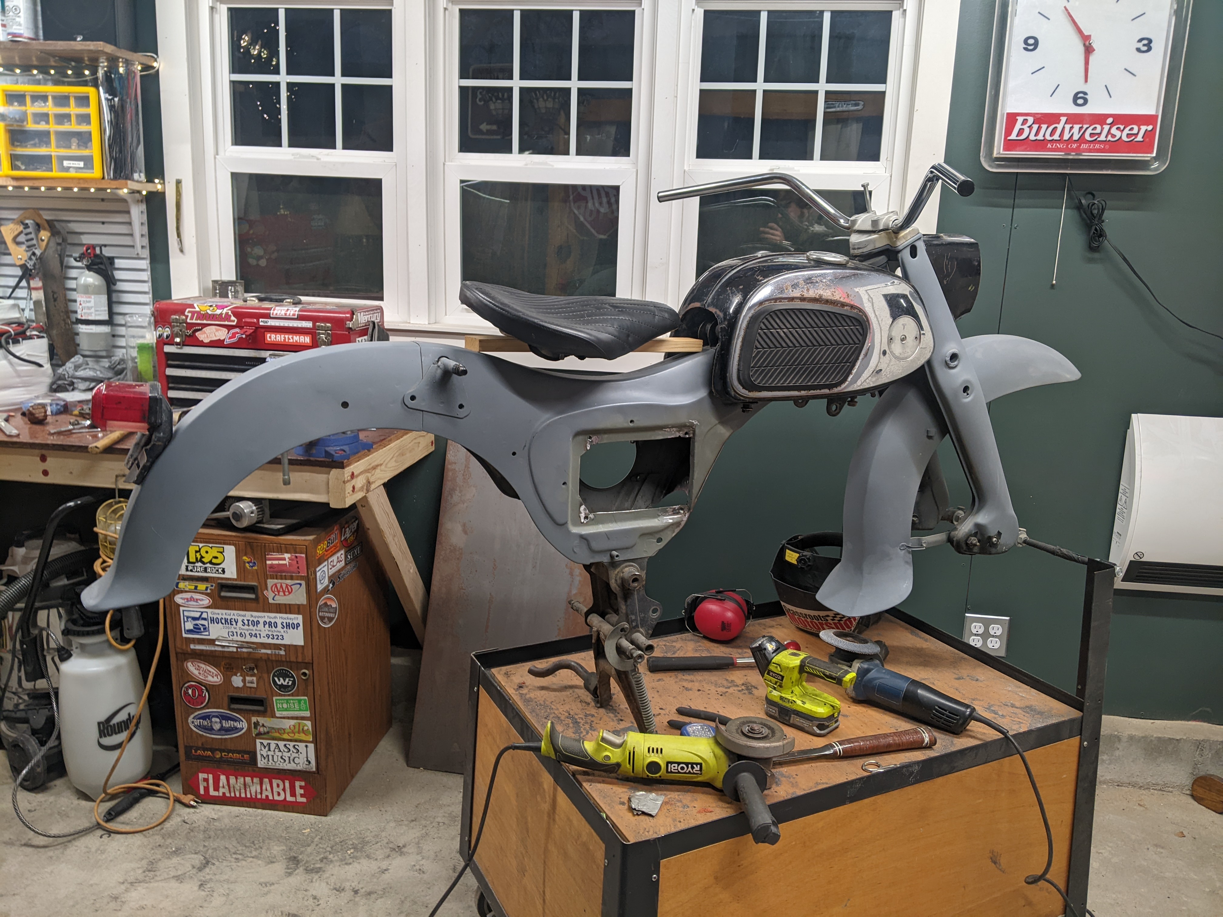
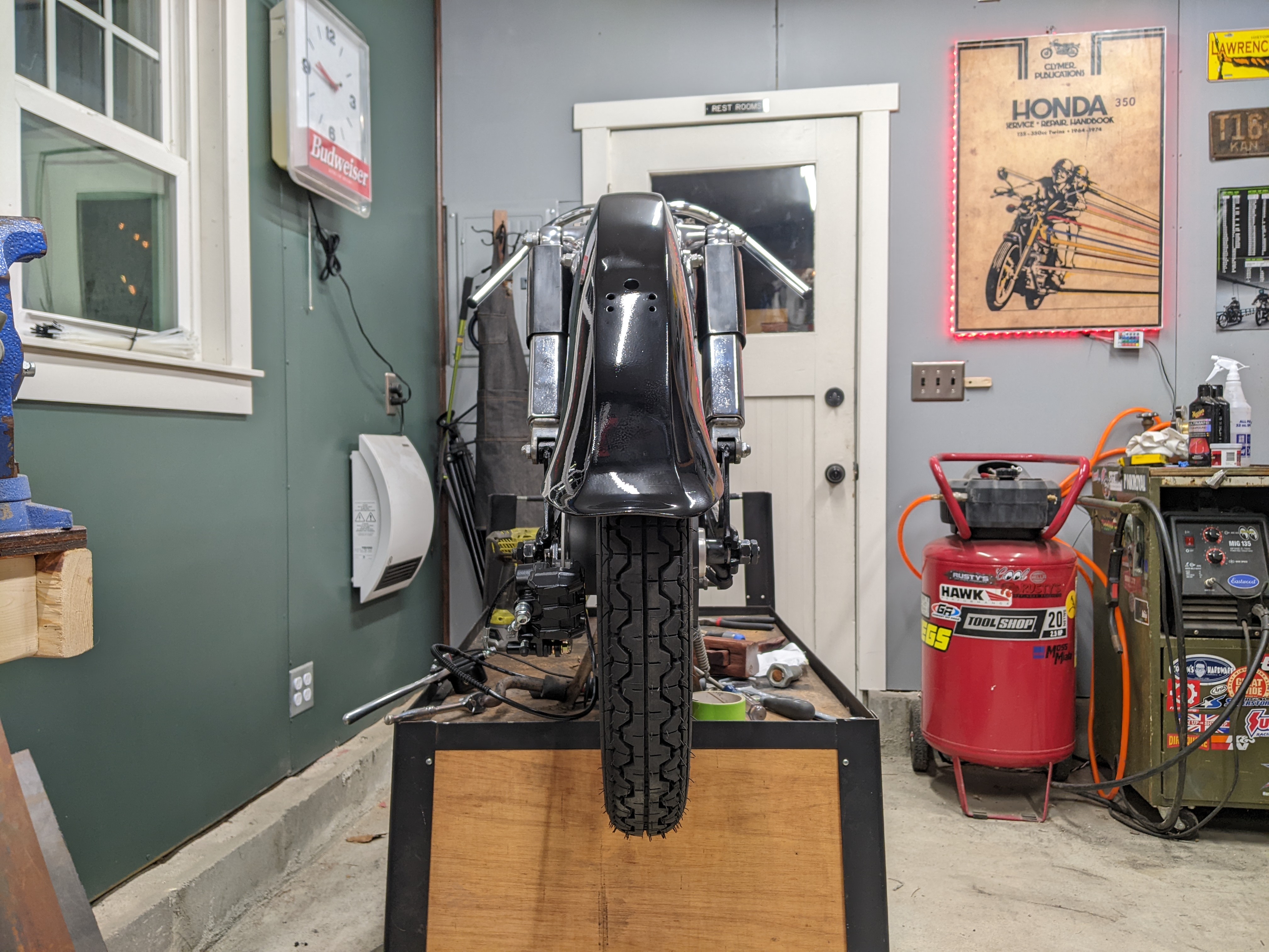
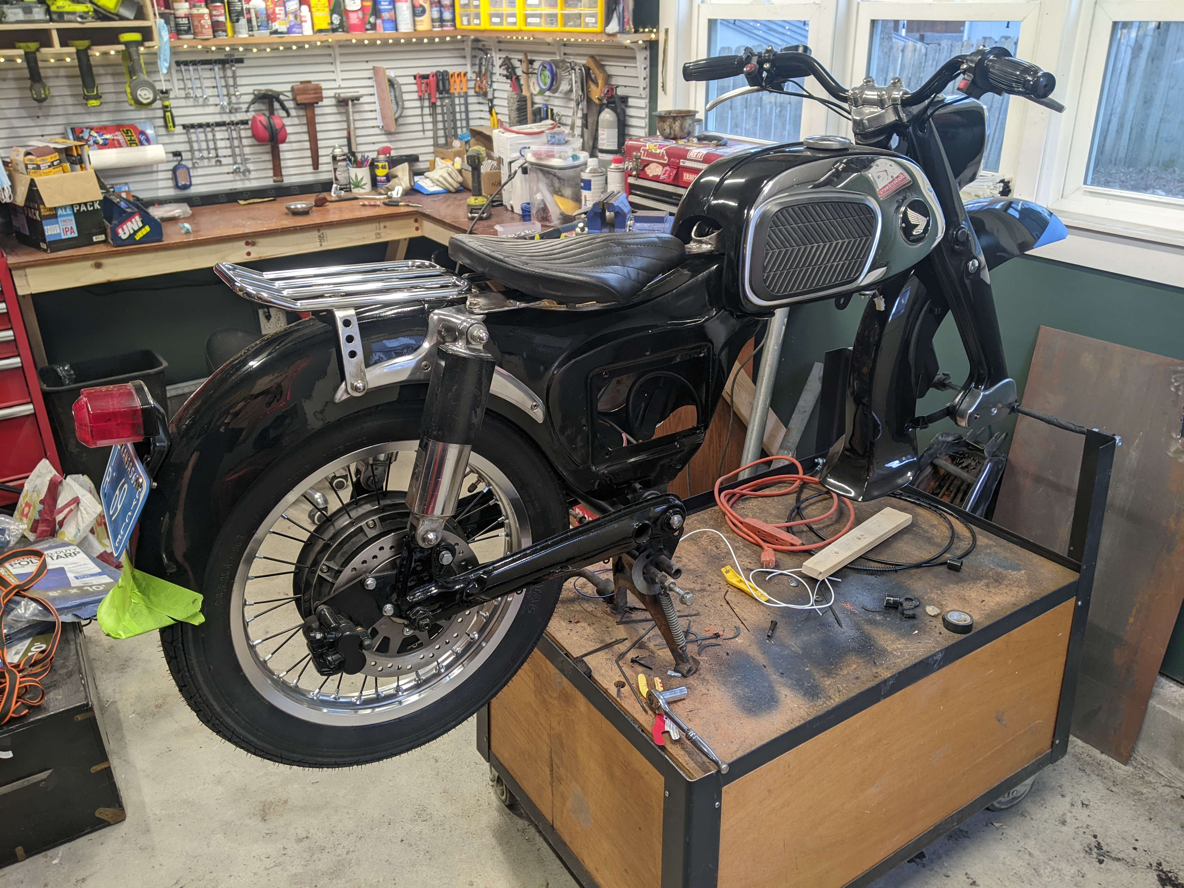
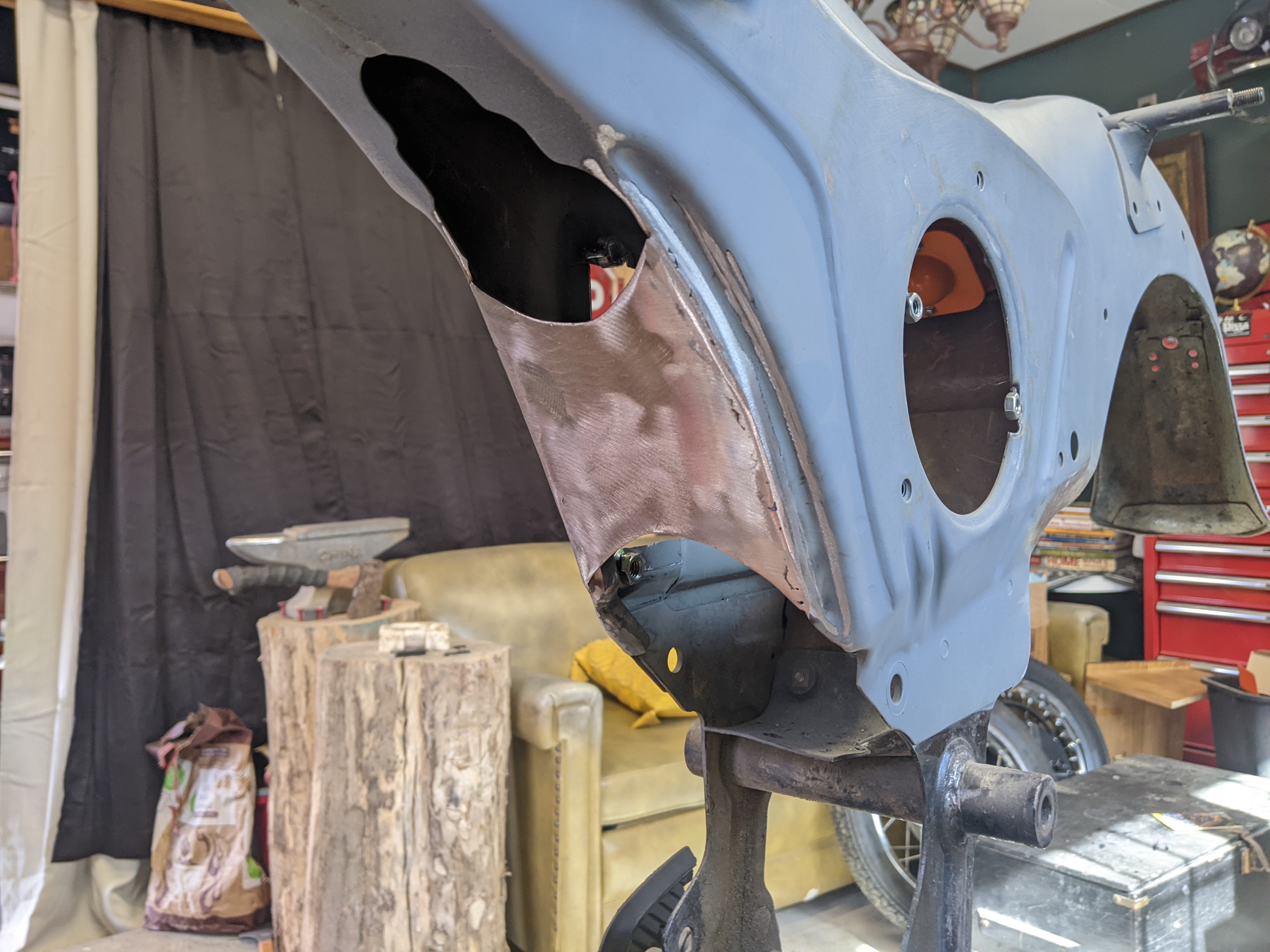
I needed to reinforce that lower-right corner of the frame. so i boxed it in with the other side. Originally there was a carb and air-box in that space, but that is no longer needed.


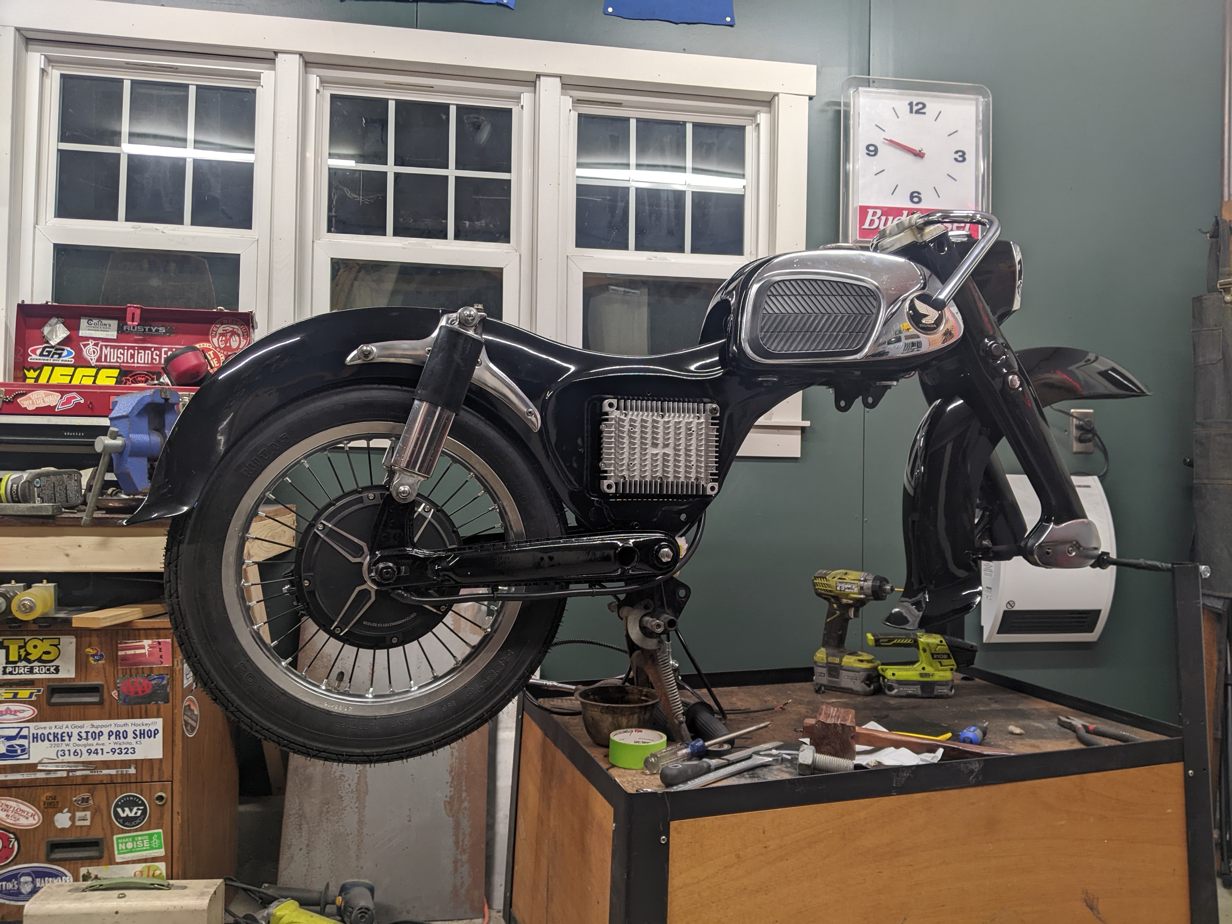
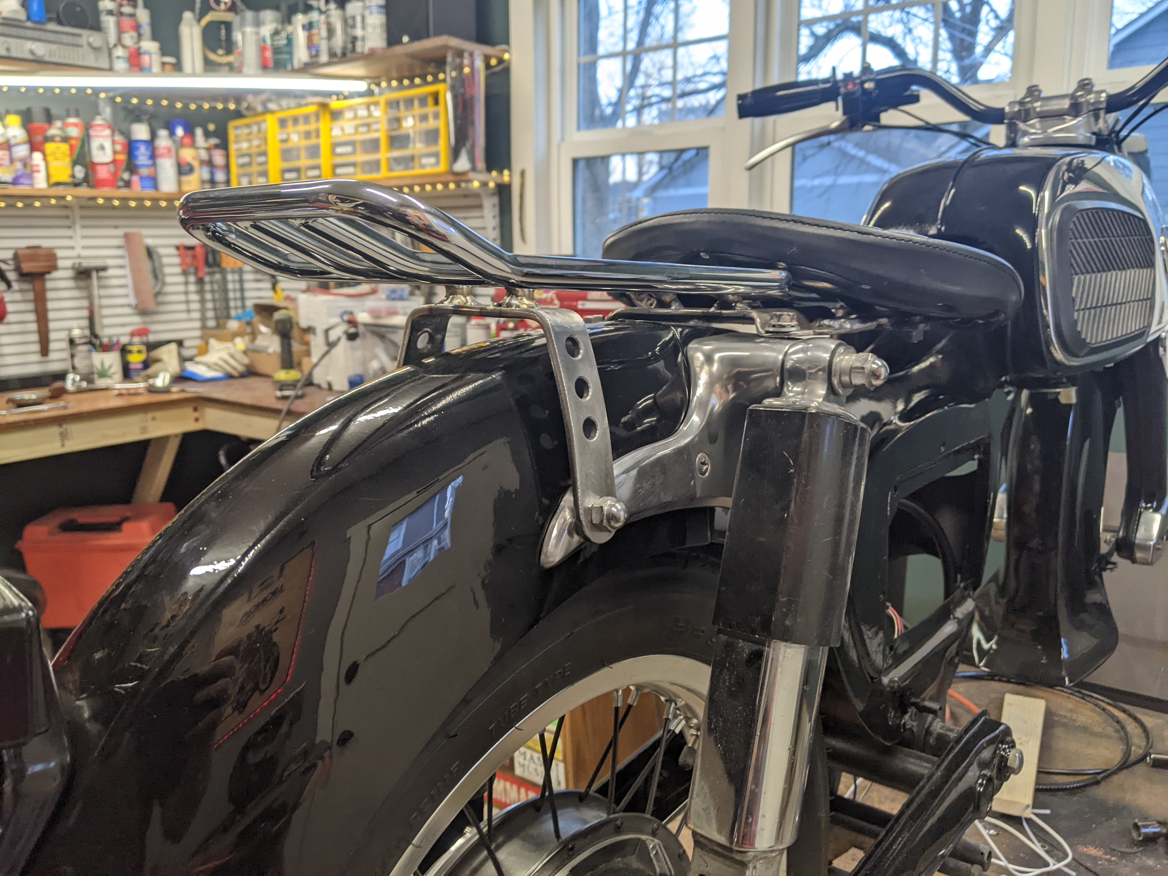
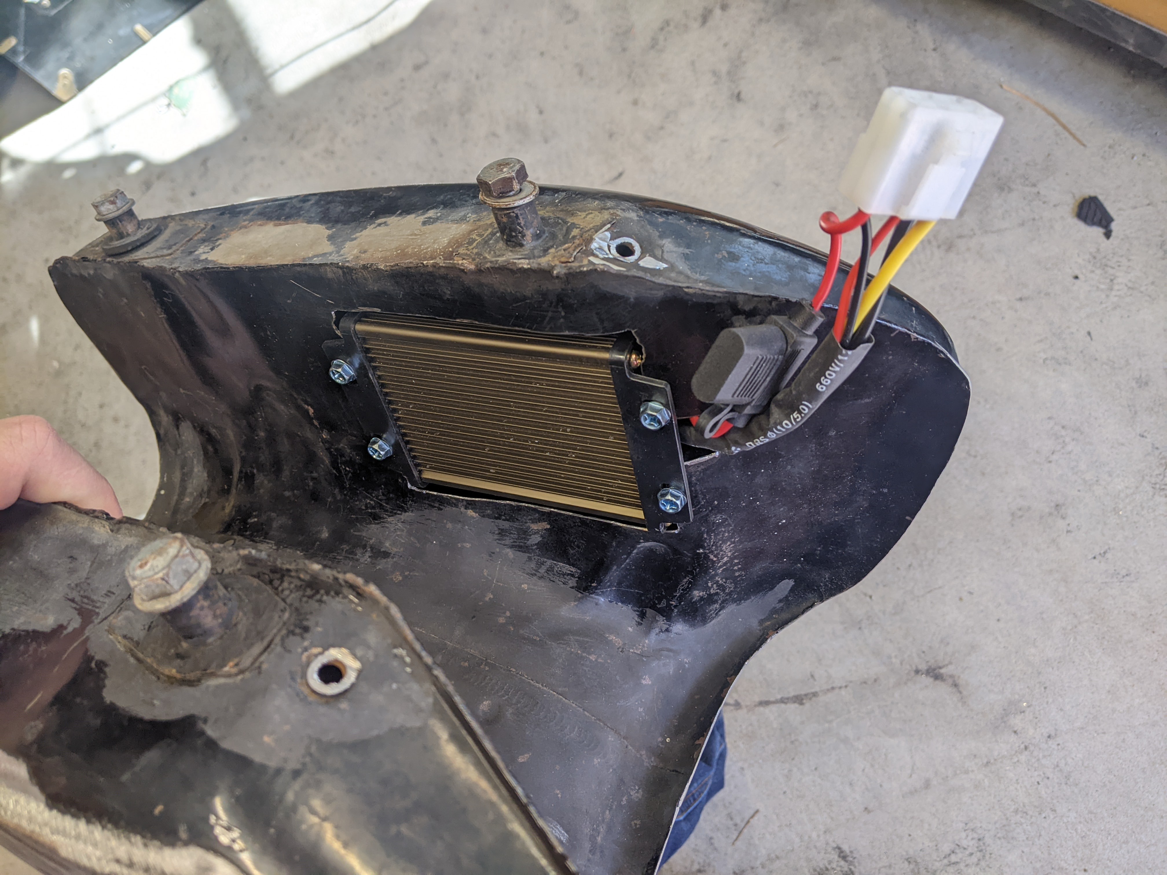
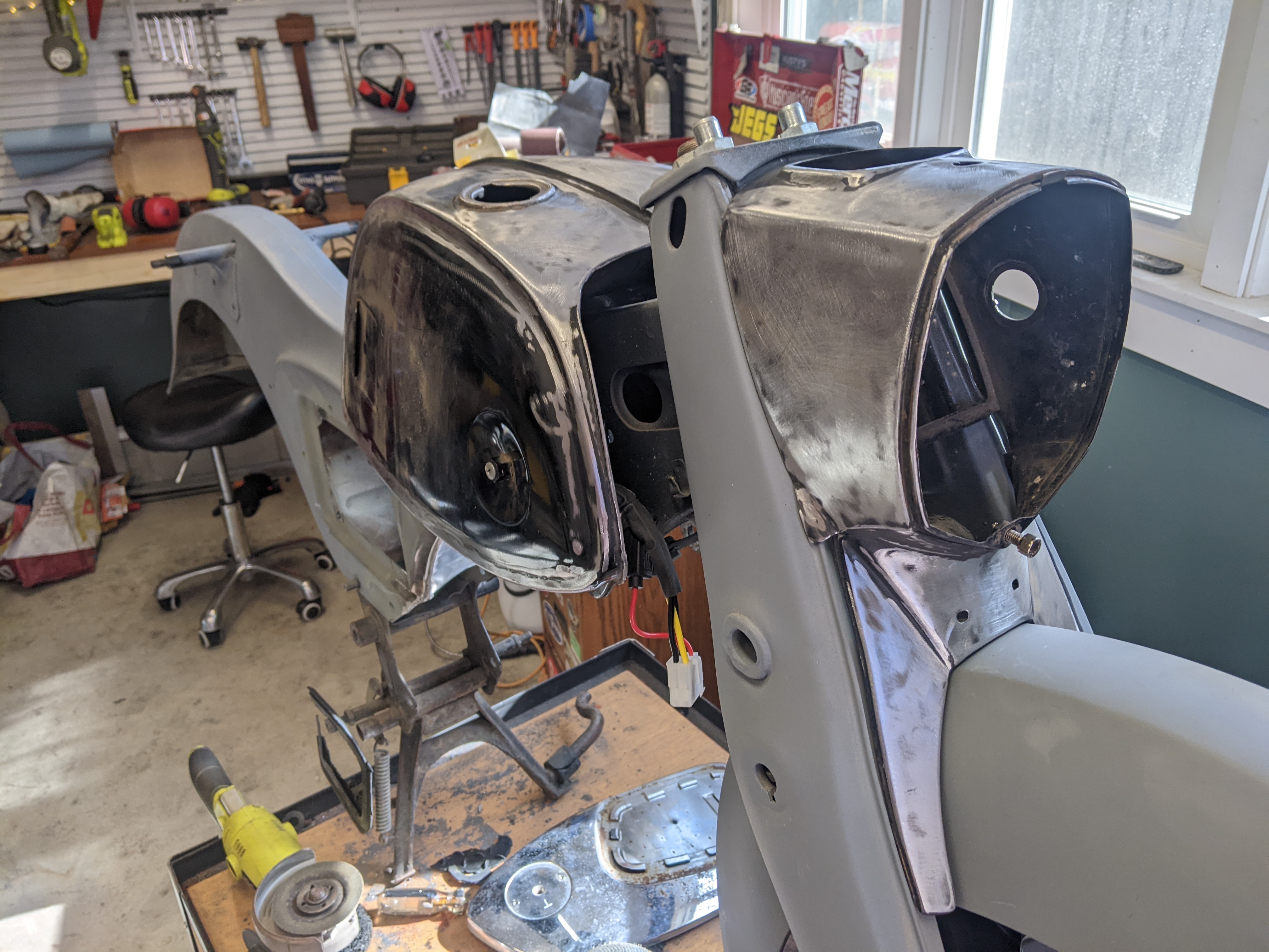
Now that i had the motor controller mounted, I moved on to mounting the dc-to-dc converter. I cut a hole on the inside section of the gas tank, and it fits inside the tank now. Perfect.


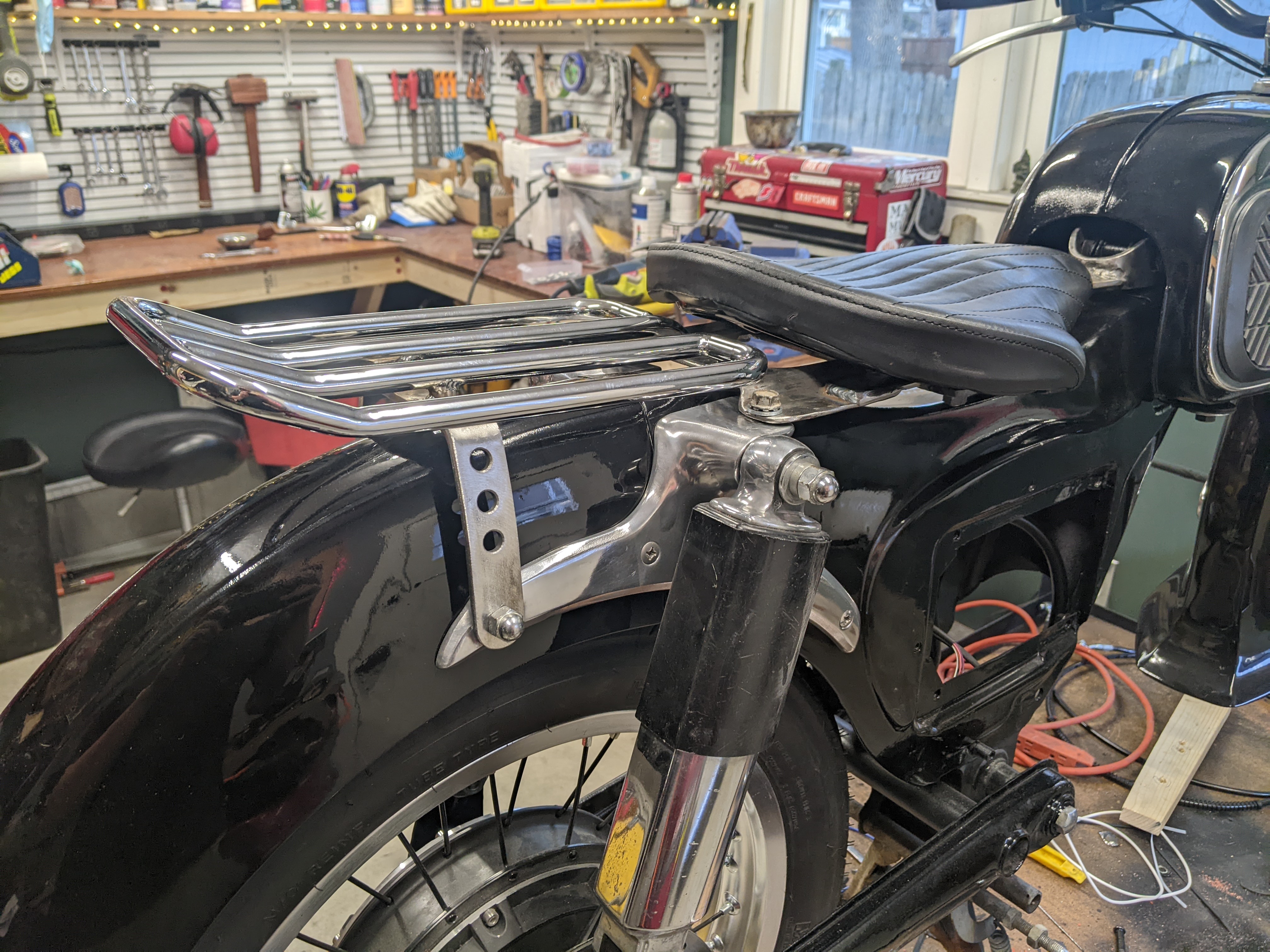
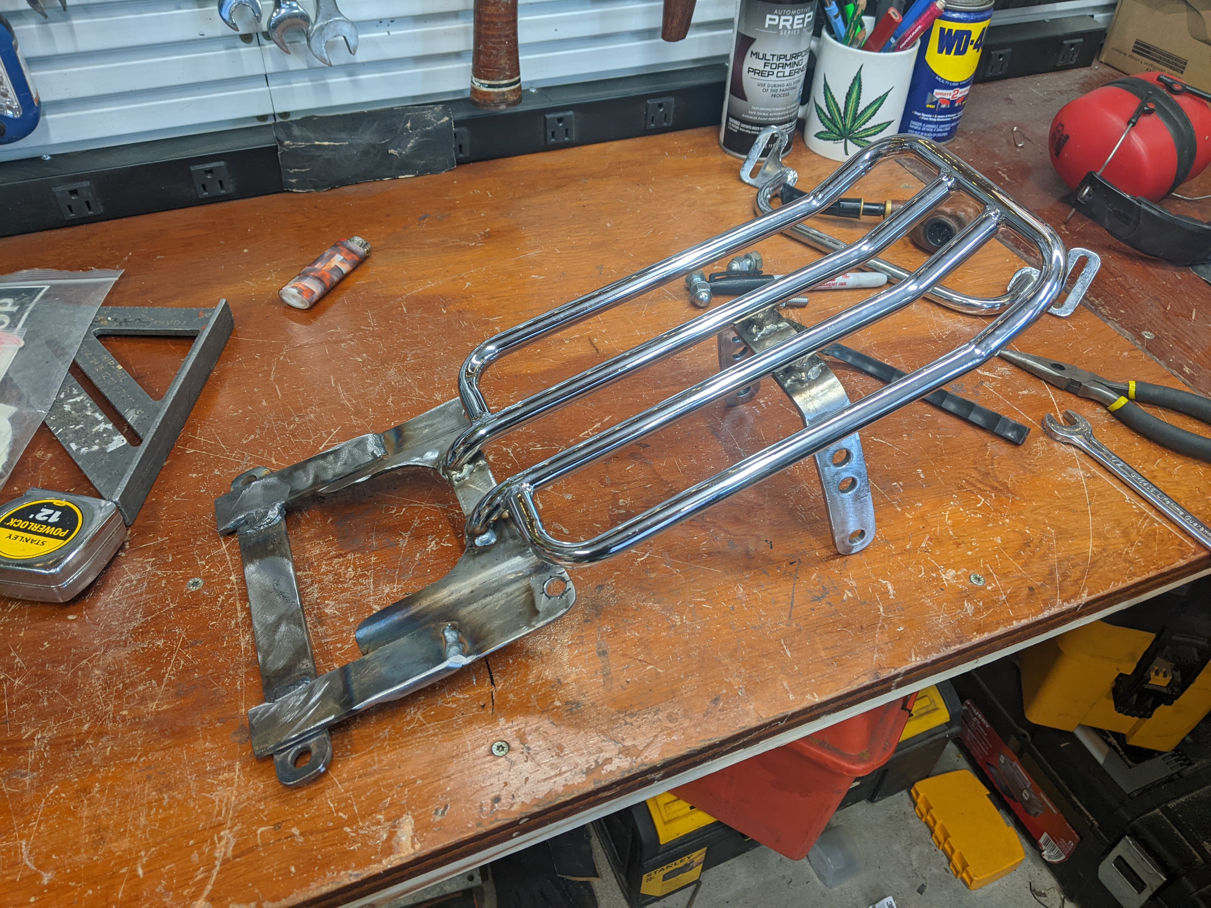
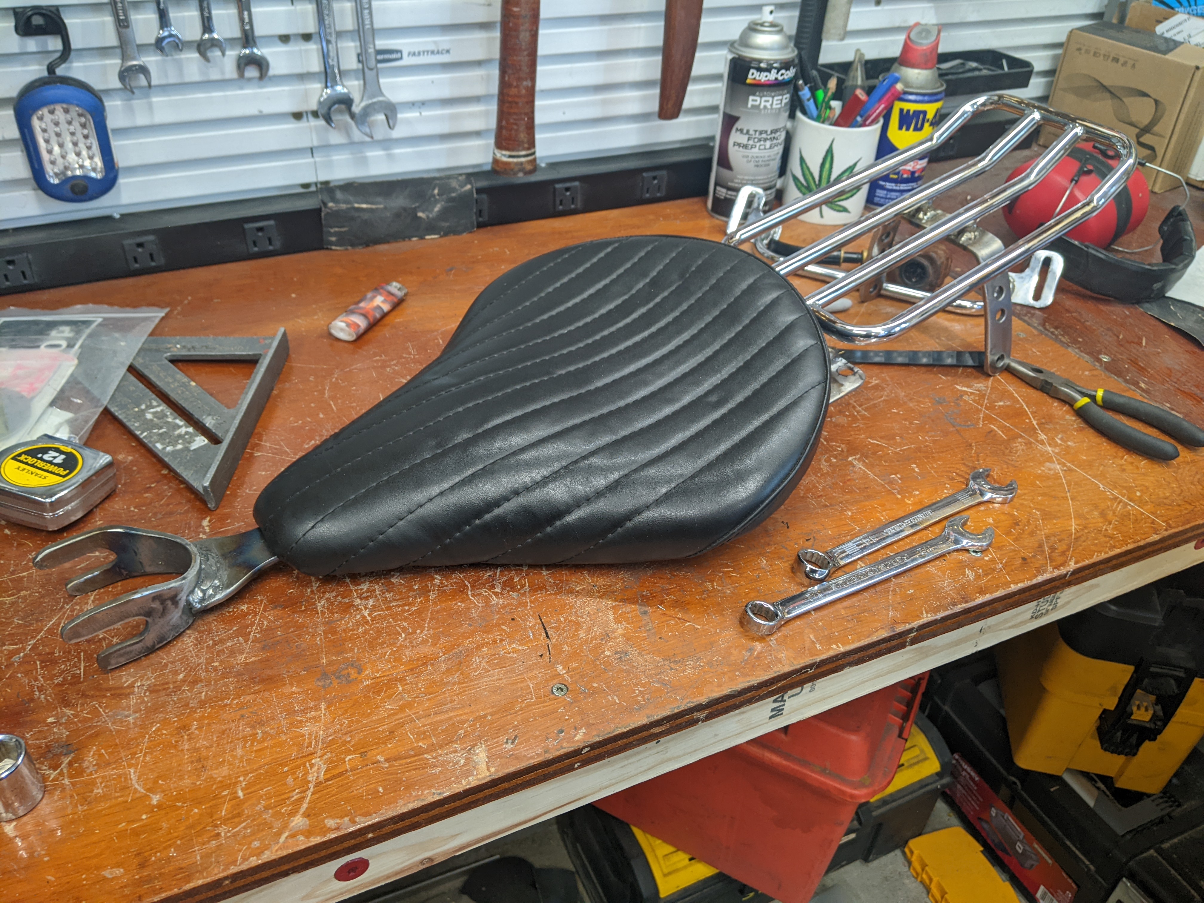
I also picked up this solo seat at a swap meet last weekend. Im not 100% sure i will use it but i will keep it for this project for now.

 
mannydantyla said:
I needed to reinforce that lower-right corner of the frame. so i boxed it in with the other side.


I didnt really like the huge cutout for the controller,
because it weakens the frame considerably in my opinion,
but with this modification it should be OK now. :thumb:

Although I would have gone even more downwards with the cross-connection to the other side,
in order to support the real thin corner.
 
If you zoom in, you'll see there is another piece of steel welded in there. I used 1/8 inch (3mm) steel, about 2 inches long, and bent it to match the angles in the frame.

I'm also planning on building the "battery tank" to be strong enough to be a stressed member, like the old engine. I'm still working all of that out in my head though.
 
QUESTION:
Is this an appropriate location for the contactor? It's tucked deep into the frame, so it is a good use of space, and is bolted down nice and tight. But is it OK to put the high-voltage components just wherever its convenient or do they need to be in an isolated box?

PXL_20220210_203730812.jpg


ONE MORE QUESTION:

Should I bench test everything before bolting it all to the motorcycle?
 
Place of contactor seems fine. I would make sure no short can occur to the frame off course. So some isolation (coating) inside the frame would be advisable.
Bench testing is smart as it is less likely to make mistakes in the wiring. The overview is much better. Just a little more work.

BTW I like the seat option :thumb:
 
mannydantyla said:
...
is it OK to put the high-voltage components just wherever its convenient or do they need to be in an isolated box?
...
Should I bench test everything before bolting it all to the motorcycle?

Well.. I think this cant be said generally.
It strongly depends on where and how you intend to use the bike.
For an offroad bike which will be used on muddy roads,
and maybe even high-pressure cleaned,
other precautions might make sense
than for a street bike which will drive mainly on tar roads and in dry weather.

And as for the bench testing:
I did it.
Too lazy to search for problems in inconvenient places...
 
Thanks guys. I will of course put rubber boots on all the connections, and maybe I'll cut up some plastic and put that on the inside of the frame to really make it impossible to short out.

Hmm, I wonder if I could get some non-conductive wrenches...
 
Time to start putting all the parts on the frame!


The disc brake bracket is perfectly secured to the tab I welded to the swingarm. This also would keep the wheel from sliding off of the swingarm if the nuts ever become loose.


Houston we have a problem!


The rear wheel offset way to far to the right. I know that the rim offset can be adjusted by tightening one side of the spokes and loosening the other side, but this is so much offset that I don't think any amount of spoke adjusting can correct it.

Maybe I should have payed more attention to the hub dimensions.


However that is not the only problem.

The brake disc is rubbing against the shock hardware. Maybe I could try using a thin jamb nut instead, but it would be really really close.


So I'm pretty sure I'm going to remove the disc brakes completely, allowing me to move the whole wheel to the left and put a spacer on the right, that would correct the offset problem.

And instead of having rear disc brakes, I will use variable regen braking. The motor controller I'm using allows for a throttle-style input to control the amount of regen braking, and a few people have even recommended I use this instead of mechanical brakes. I would use a electric brake lever like this - https://flipsky.net/collections/new-arrival/products/brake-handle-aluminium-electric-scooter-brake-handle-clutch-lever-replacement-for-max-g30-parts - or a normal brake lever connected to a throttle potentiometer...?

It would also eliminate that strange condition of having drum brakes on the front wheel and disc brakes on the rear...

Do you agree that it is a good idea to use only regen braking and have no rear bakes? I have no idea how strong it can be. There is still a front hub brake, of course.
 
I just don't know how much braking power I can get out of the regen function. Will it be enough? We're also talking about the rear wheel which is secondary to the front wheel brakes.

Also, the disc is interfering only with the nut, which is redundant because the bolt is fist threaded into the aluminum end of the shock. I just removed the nut only, now the wheel spins freely with a couple of millimeters between the end of the bolt and the brake disc. But I wouldn't be able to move the hub any further to the left within the swingarm.

I think another possible solution to the wheel offset problem is to shift the whole swingarm over to the left ~15mm. That would probably require further modifying the frame, which I'm wouldn't want to do in case i want to revert it back to gasoline powered. I still have the old engine which is rebuild-able I think. I still have all the old parts like the mufflers, carbs, air intake, etc.

I think I will remove the disc brake and see how far and I can fix the offset by using shims/washers/spacers.

My two option:

  • remove disc brake and only use regen braking for the rear wheel, hopefully this will give me the room for adjustment to move the hub to the left within the swingarm. Will also need a new arm/bracket to fasten the axle to the tab on the swingarm so that the wheel can't slide off if the nuts are loose.
  • modify the swingarm mount on the frame, and keep the disc brake but not use the nut on the shock bolt. (the bolt is first threaded into the shock, the nut is just for added security? use locktight instead)

Any potential problems with either of those two options?
 
mannydantyla said:
I will use variable regen braking. The motor controller I'm using allows for a throttle-style input to control the amount of regen braking, and a few people have even recommended I use this instead of mechanical brakes. I would use a electric brake lever like this - https://flipsky.net/collections/new-arrival/products/brake-handle-aluminium-electric-scooter-brake-handle-clutch-lever-replacement-for-max-g30-parts - or a normal brake lever connected to a throttle potentiometer...?

Or -as " j bjork" proposed me in my build thread- use a thumb throttle for braking....

In my opinion, just a "switch" (e.g. brake on/brake off) for regen braking would not be very useful.
Especially not if it is meant to replace a "real" brake.
A "real" braking function has to be variable, in my understanding.
 
I was under the impression that that part was more than just a switch, it was like a throttle, but there's not much description. It was featured in this video - https://www.youtube.com/watch?v=lidW69cRnZM - and he calls it the "brake throttle"

I think I'll just get a cable to potentiometer (sp?) box and use a normal brake lever that matches the front brake.

Oh, and I got the wheel centered in the bike now, removed the disc brake and moved some spacers around.
 
Well I have decided to use the disc brake, and make it fit by shifting the swing arm to the left by modifying how it mounts to the frame and to the shocks.
 
mannydantyla said:
Well I have decided to use the disc brake, and make it fit by shifting the swing arm to the left by modifying how it mounts to the frame and to the shocks.

If you have access to a lathe you could turn down the diameter of the brake disk by just enough that it clears the nut by a few millimetres. It looks like a 1/2" reduction in diameter would be enough to clear the nut and still have some metal above the outer holes of the disk. You'll have to also adjust the brake caliper bracket to the new diameter of the disk.
 
Thanks SlowCo but the real problem is not the clearance between the disc and the shock's nut, it is the fact that the hub is not in the center of the axle, which causes the wheel to not be in the center of the bike. If I remove the brake caliper mounting bracket, which rides on the axle, then there is room to shift it over and put a spacer on the other side.

However, I think I have a better solution that allows me to center the wheel in the bike while also keeping the brake.

Someone on a facebook group suggested flipping the wheel over and seeing if it fits any better. I asked, but wouldn't that cause the wheel to accelerate in reverse? But if I can control the direction that the motor spins via the programmable controller, then problem solved.

So I flipped the wheel over a LO AND BEHOLD IT FITS!

FMn_uupX0AQJM7c.jpg


I would just need to re-jigger the spacers and weld a tab onto the right side of the swingarm for the caliper mount.

Question: The Kelly controller does allow me to program the wheel spin direction, right??
 
Good solution :thumb:

mannydantyla said:
Question: The Kelly controller does allow me to program the wheel spin direction, right??

Yes, sure.
With my KLS7245N there is a checkbox in the "vehicle" tab, called "change direction".

And don't forget-some tires are supposed to be mounted on the rim with a special direction, too.
 
Yes I see in the controller's documentation that there is a "change direction" feature:

(28)Change Direction:
If the direction is not what you expected after finish the Identification angle operation,please just choose Change Direction item.
Please click Write button to activate Change Direction function.The motor direction will be what you expected after the power supply is reset.
Suggestion:factory default is Disable.
 
I got the handlebars and hand controls finished, and got started on the seat mounting brackets. Gotta make sure my fat ass doesn't break the welds so I used my 240v stick welder on the 3/16" steel.

PXL_20220304_021459933.jpg


The switch next to the left grip is the kill switch, very important to have on a DIY EV build, needs to be easy to push with both hand still on the bars, in case something something goes wrong such as the throttle wires short out and cause wide-open-throttle.

The switch on the right which came built into the throttle will be used for the turn signals.

PXL_20220304_020842198.jpg


The seat bracket attaches to the bushings that the OEM seat used. Here's the close up of the welds:

PXL_20220304_020846580.jpg


I'm also thinking about putting a filler plate to make it look a bit better. Might also be a good place for a switch.
 
New video!

https://youtu.be/w1MxRkxH6EA
[youtube]w1MxRkxH6EA[/youtube]

There's a pretty cool thing at the end of the video that I haven't shown this forum yet
 
I've officially begun the wiring! Kinda, I mean, I've tried to start on the wiring. The first step was to put together a wiring diagram, but that was when I realized I had a problem:

It turns out that the 72v contactor that I bought from Kelly (KZJ400A) doesn't mean that the main lugs are rated for 72v - it means that the coil is rated for 72v. I confirmed this myself by trying to open it with a 12v lead acid battery (didn't open) and then my 72 battery pack (opened with a nice kick!).

Only problem with that is that I really don't want to run 72v through my kill switch and my ignition (key) switch. I've seen from a few people (JimVB, for example) that they were able to run the 72 volts (it's only drawing an amp or less) through the OEM switch without problems. But my ignition switch was actually made for a 6v circuit! And then there's the kill switch, which has an interal LED that would go up in smoke if given 72 volts.

So I ordered a different contactor. I got this TE LEV200 but off Ebay for only $70 including shipping, and is shipped from within my country and not from overseas. I thought that was a fair price, EVwest has similar style contactors selling for $169.
 
Back
Top