Hello Everyone,
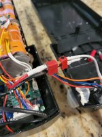
I had an old battery inside a black container that slides into a holder on my ebike that needed to be rebuilt. The battery was a 36 v 10s5p configuration and there was room within the black case for a 36 V 10s6p so that is what I upgraded to. The batteries I purchased for the rebuild were all tested at 3.4 volts and all the series are at 3.4. The 3 - 3 - series voltage is 10.1 as expected and the total voltage of the battery pack is 34 volts. I have installed the battery onto my ebike and everything works well. I tested the bike up a few steep hills to test a load and it climbed with no issues. The battery level on the ebike states below 3/4 full and the gauge on battery states 1/2 full. cells are Samsung ICR18650 26J. Checked 30 amp fuse and it's good.
So here is the issue: the battery will not charge!
I've checked the 2 battery chargers that I have and they work on my other batteries, putting out 41 volts at 2 amps. The charging port is a two wire prong (5.5mm x 2.1mm coaxial) with the positive in the center and the negative is on the outside. I've confirmed that the new charging port is working in side the battery. Both chargers react the same, red light on, yellow charge light comes on for a second, and then the green charge light comes on. I think I can weed out a bad charger seeing it works on both of my other ebike batteries.
The other thing I've done is reset the BMS as well as removed the battery from the case, away from the BMS and tried to just charge the battery standalone and the same results as stated above. I'm confused why this battery will not charge and I don't know what my next move might be. Any help or suggestion would be appreciated. Is there some type of protection within the cells that is stopping the charge? The cell are unprotected. Would draining the battery down to a lower voltage help?
Vr-Dc ebike rider (EbikeDC)
Last edited:
")