New to battery diy ?? Read these VERY INFORMATIVE documents

Doctorbass

100 GW
Joined
Apr 8, 2007
Messages
7,496
Location
Quebec, Canada East
Link added to FAQ thread.
 
Connecting Batteries in Parallel: Unexpected Effects And Solutions
http://liionbms.com/pdf/BPC2012Elithion.pdf

Li-Ion Myth-Buster
http://liionbms.com/pdf/ElithionBatteryPower10.pdf

Doc
Just read the first PDF, brilliant info, but a fair bit to take in, I'm totally new to Li - * (anything), but luckily do know a bit about electronics n electricity.

First (think I know the answer but to be sure) when you refer to the difference between putting batteries in // at the factory as opposed to the field, I assume you mean at the time of manufacture, vrs field i.e. if you made two identical packs of home, and put them in // at that point.... No Problem, the problem occurs when you have two packs that are in use and have a dif SOC.?

Second (still trying to let this all sink in) what would happen if you two had identical packs same SOC, and you connected the pack - from pack A to the p- charge of pack B and vice versa, possibly thru big diodes, would this keep the two packs constantly balanced with respect to each other.? ...... Now I think I'm overthinking this now as I suspect you don't need to even consider this as just connecting the two pack -ve with do the same job?

Third what about when it comes to charging the two packs up? Obviously if you start charging one, while still connected to the other, while you dont get an immediate inrush to the other, basically what happens or how should you do it? isolate them from each other again till they are both equally charged?

Finally I think you said never directly connect two packs ex thu a resistor? was that just in the field, or would you still need one if connecting two equally charged packs.

Keith

Thanks for the great PDF, (loved some of the images) will study it more, I already have built several identical packs, working out how to best use them.
 
When two batteries are in parallel, if you put the charger into the first pack, it will charge the second pack thru its output. If the second pack does not have a single port BMS, you may not have any charge protection on that battery. Unless you know it's OK, it is always safer to break the parallel connection and charge the two batteries separately,
 
When two batteries are in parallel, if you put the charger into the first pack, it will charge the second pack thru its output. If the second pack does not have a single port BMS, you may not have any charge protection on that battery. Unless you know it's OK, it is always safer to break the parallel connection and charge the two batteries separately,
Thanks doc

TBH not come across the term single port BMS yet. Both batteries are built by me, both have identical BMS fitted, I was going to use them on the bike as seperate batteries (use up one then switch to 2nd one). The putting in // was an after thought (and could have many advantages). They both have their own BMS with THREE WIRES......... pack -ve thru BMS......... -ve charge thru the BMS,...... pack +ve from the +ve of the pack, if that helps identify the BMS type. I THINK That would mean if still connected together the second battery would not be protected by its BMS, UNLESS you also connect the pack -ve charge wires from both packs together as well, then charge both from a single charger? That way both packs would be protected by their own BMS, and as the two packs are still connected to each other they should in theory remain in balance to each other (same way as groups of parallel cells in a battery remain all the same voltage. Or am I missing something?

TBH I'm thinking all this out as I go along, "On a Now what do I do basis?".

keith
 
Connecting Batteries in Parallel: Unexpected Effects And Solutions
http://liionbms.com/pdf/BPC2012Elithion.pdf

Li-Ion Myth-Buster
http://liionbms.com/pdf/ElithionBatteryPower10.pdf

Doc

Thats a lot of certified study information for a weekend.. (study 8h a day equals 16h weekend x2 pdf & read twice.. )
very usefull info for those that keep searching for tha one (similar to matrix movie) or to learn some lithium electronics knowlgment.

Anyone repaired or builted any battery that later time went into fire or malfunction?
how much sucess/fail rate you have at all your lithium works? How many lithium batteries you managed total?
"Why U ask that?thats not Ur business"
 
Last edited:
When two batteries are in parallel, if you put the charger into the first pack, it will charge the second pack thru its output. If the second pack does not have a single port BMS, you may not have any charge protection on that battery. Unless you know it's OK, it is always safer to break the parallel connection and charge the two batteries separately,
There are only hundred electronic rules for paralleling different batteries (possible to parrallel any stuff, but under some rules.. "sarcasm" :unsure:

1st Make sure same voltage or similar at parallel connecting moment (curent flow from one to other battery only depends on the two batteries voltage difference and internal resistence summed & using ohms law to get amperes) (example one battery 50mOhm at 60V connect to a 67V battery 100mOhm, sooo I = U/R means volts difference 7V divided by 150mOhm means 47A initial charge flow.. this maybe ruins bms charge port mosfets or if ghost bms(guess brand?) it will put out 47A to cells, if a 5P battery means 47/5 equals almost 10A charging current per cell..)

2nd MAKE SURE BOTH battery BMS's have COMMUN Charge/Discharge PORT ( if U dont care about this, soon U maybe get a fire anywhere in tha future or if Ur lucky maybe not, just a parallel battery malfunction.. and if uR lucky not to be attached to a ghost bms similar to surreal artist, search on web "dali paintings" daly? :mrgreen:

More content to be included at pdf document :coffee:

Is possible to parallel different chemistries & different number Serial elements battery ex. LiIon and LiFePO4 (3S // 4S) =7S? :unsure:
Yes, butt
, make sure both bms's have commun charge discharge port! No, 3S parallel with 4S equals 3,5S:unsure:
the LithiumIon battery example 12V nominal work at interval 12,6V down to 9V (3S) and LifePO4 (4S) is a 4S range max 14,4V down to 10V
soo at math we have commun interval for matching different elements
this means both batteries will work in parallel at interval 12,6V down to 10V
under 10V only 3S lithium battery output (from 10V to 9V), and above 12,6V only LiFePO4 battery working (from 14,4V down to 12,6V)

This is considered a unstable electronic system because behavior changes along voltage curve(paralleling 3S LiIon with 4S LiFePO4 will make a 14,4V down to 9V wide voltage range battery..)

Allways include a commum charge/discharge port bms at any battery and avoid separate charge/discharge ports(unless U know what Ur doing, but thos ports could run into unprotected state and lithium cells could be crazy to go on fire!! soo avoid that!)
Shakira says put a ring on it, and also says, put a commun charge/discharge port bms at all batteries worlwide! that will save a lot of complicated situations.. :poop:

A great weekend for everyone :bigthumb:
 
Last edited:
There are only hundred electronic rules for paralleling different batteries (possible to parrallel any stuff, but under some rules.. "sarcasm" :unsure:

1st Make sure same voltage or similar at parallel connecting moment (curent flow from one to other battery only depends on the two batteries voltage difference and internal resistence summed & using ohms law to get amperes) (example one battery 50mOhm at 60V connect to a 67V battery 100mOhm, sooo I = U/R means volts difference 7V divided by 150mOhm means 47A initial charge flow.. this maybe ruins bms charge port mosfets or if ghost bms(guess brand?) it will put out 47A to cells, if a 5P battery means 47/5 equals almost 10A charging current per cell..)

2nd MAKE SURE BOTH battery BMS's have COMMUN Charge/Discharge PORT ( if U dont care about this, soon U maybe get a fire anywhere in tha future or if Ur lucky maybe not, just a parallel battery malfunction.. and if uR lucky not to be attached to a ghost bms similar to surreal artist, search on web "dali paintings" daly? :mrgreen:

More content to be included at pdf document :coffee:

Is possible to parallel different chemistries & different number Serial elements battery ex. LiIon and LiFePO4 (3S // 4S) =7S? :unsure:
Yes, butt
, make sure both bms's have commun charge discharge port! No, 3S parallel with 4S equals 3,5S:unsure:
the LithiumIon battery example 12V nominal work at interval 12,6V down to 9V (3S) and LifePO4 (4S) is a 4S range max 14,4V down to 10V
soo at math we have commun interval for matching different elements
this means both batteries will work in parallel at interval 12,6V down to 10V
under 10V only 3S lithium battery output (from 10V to 9V), and above 12,6V only LiFePO4 battery working (from 14,4V down to 12,6V)

This is considered a unstable electronic system because behavior changes along voltage curve(paralleling 3S LiIon with 4S LiFePO4 will make a 14,4V down to 9V wide voltage range battery..)

Allways include a commum charge/discharge port bms at any battery and avoid separate charge/discharge ports(unless U know what Ur doing, but thos ports could run into unprotected state and lithium cells could be crazy to go on fire!! soo avoid that!)
Shakira says put a ring on it, and also says, put a commun charge/discharge port bms at all batteries worlwide! that will save a lot of complicated situations.. :poop:

A great weekend for everyone :bigthumb:
So my two identical li po pouch battery packs each with three wires..... P +ve......... P-ve (via BMS) -ve charge (via bms), equalise voltage then connect the p2 +ve together, the p2 -ve together and the 2 -ve charge together right?

Keith
 
Last edited:
Thanks doc

TBH not come across the term single port BMS yet.

Single port or common port means that the BMS doesn't have separate C- (charge) and P- (discharge) pads (ports) on it, so all charge and discharge goes thru the same port (even if there are separate connectors on the outside of the battery casing). The FETs are wired in series, so that either one can block the current flow to or from the battery as needed, so you can charge and discharge from the same wiring safely.

Dual port or separate port means that C- and P- are completely separate, and this is the most common type. It means that you must keep all charge wiring separate from all discharge wiring, and you can't charge thru the discharge port or discharge thru the charge port safely, as the BMS can't block this from happening when a limit is exceeded, so it can't protect the cells (because FETs act as uncontrolled diodes in the reverse direction, and controlled switches (or variable resistors) in the forward direction).


With common port BMS, you can parallel same-voltage packs and they're safe to charge together or discharge together; the BMS will still protect each one as needed.

With separate port BMS if you charge them while the P- ports are still paralleled, then neither pack can protect against overcharge, etc. The diode mode of the FETs means that the discharge ports (normally still on while charging in most BMS, though a few do turn it off) can pass current out on either pack, but the one that has shut it's charge port off can't stop current from still flowing into it thru the discharge port, out of the other pack that's still being charged, so it can continue to overcharge whatever cell hit HVC and is now trying to stop being charged.

Similarly, the charge ports will still let current flow out of a battery that has hit LVC when the ohter pack is still discharging, if the C- ports are still paralleled during discharge.


One reason both kinds are still made is that the separate port versions have less heating and power loss inside the BMS without the second set of FETs always being "in the way" in diode mode (or resistive switch mode if still "on"). And the single port versions are made because they can be used in ways the others can't, and simplify external wiring.

They both have their own BMS with THREE WIRES......... pack -ve thru BMS......... -ve charge thru the BMS,...... pack +ve from the +ve of the pack, if that helps identify the BMS type.
Those sound like the dual or separate port BMS. You can parallel them, but only the ports you are actually using at the time. If discharging, only parallel the P- ports. If charging, only parallel the C- ports. Disconnect / unparallel the ports you are not using.
 
Single port or common port means that the BMS doesn't have separate C- (charge) and P- (discharge) pads (ports) on it, so all charge and discharge goes thru the same port (even if there are separate connectors on the outside of the battery casing). The FETs are wired in series, so that either one can block the current flow to or from the battery as needed, so you can charge and discharge from the same wiring safely.

Dual port or separate port means that C- and P- are completely separate, and this is the most common type. It means that you must keep all charge wiring separate from all discharge wiring, and you can't charge thru the discharge port or discharge thru the charge port safely, as the BMS can't block this from happening when a limit is exceeded, so it can't protect the cells (because FETs act as uncontrolled diodes in the reverse direction, and controlled switches (or variable resistors) in the forward direction).


With common port BMS, you can parallel same-voltage packs and they're safe to charge together or discharge together; the BMS will still protect each one as needed.

With separate port BMS if you charge them while the P- ports are still paralleled, then neither pack can protect against overcharge, etc. The diode mode of the FETs means that the discharge ports (normally still on while charging in most BMS, though a few do turn it off) can pass current out on either pack, but the one that has shut it's charge port off can't stop current from still flowing into it thru the discharge port, out of the other pack that's still being charged, so it can continue to overcharge whatever cell hit HVC and is now trying to stop being charged.

Similarly, the charge ports will still let current flow out of a battery that has hit LVC when the ohter pack is still discharging, if the C- ports are still paralleled during discharge.


One reason both kinds are still made is that the separate port versions have less heating and power loss inside the BMS without the second set of FETs always being "in the way" in diode mode (or resistive switch mode if still "on"). And the single port versions are made because they can be used in ways the others can't, and simplify external wiring.


Those sound like the dual or separate port BMS. You can parallel them, but only the ports you are actually using at the time. If discharging, only parallel the P- ports. If charging, only parallel the C- ports. Disconnect / unparallel the ports you are not using.
Thanks got that now, complicated these smart diodes (FET's.....) LOL

So basically if I build a fairly simple rotary wafer switch (I can work the wiring out ok), that connects either both P- or both C- but never both I'm sorted.......... EXCEPT!

The risk I see there is if one pack were fully recharged, and the switch prematurely switched from charge mode to use mode before the pack voltages were equalised,... flash! bang! (unless I'm mistaken). So is there a simple addition to the switch I'm thinking of to prevent this ?

Suppose an intermediate setting between charge and use is easily possible. A third setting in between that could power an alarm (poss via resistors) if there was a voltage differential, but there has to be something better than that?

Or what about any voltage differential powering a relay that basically stopped the two batteries from being connected?

Or possibly "some" (for current) IN14000 series diodes (Pos IN14004 400v) in parallel to each other and but in series to resistors...... wired somehow..... Not worked that bit out yet?

Just thinking out loud, but no point reinventing the wheel if these is already an existing solution, which I assume there is?

Keith

I obviously want to make the actual use of the finished project both as easy as possible, and as idiot proof as possible (for my senior moments....;). LOL).........:)
 
Last edited:
Single port or common port means that the BMS doesn't have separate C- (charge) and P- (discharge) pads (ports) on it, so all charge and discharge goes thru the same port (even if there are separate connectors on the outside of the battery casing). The FETs are wired in series, so that either one can block the current flow to or from the battery as needed, so you can charge and discharge from the same wiring safely.

Dual port or separate port means that C- and P- are completely separate, and this is the most common type. It means that you must keep all charge wiring separate from all discharge wiring, and you can't charge thru the discharge port or discharge thru the charge port safely, as the BMS can't block this from happening when a limit is exceeded, so it can't protect the cells (because FETs act as uncontrolled diodes in the reverse direction, and controlled switches (or variable resistors) in the forward direction).


With common port BMS, you can parallel same-voltage packs and they're safe to charge together or discharge together; the BMS will still protect each one as needed.

With separate port BMS if you charge them while the P- ports are still paralleled, then neither pack can protect against overcharge, etc. The diode mode of the FETs means that the discharge ports (normally still on while charging in most BMS, though a few do turn it off) can pass current out on either pack, but the one that has shut it's charge port off can't stop current from still flowing into it thru the discharge port, out of the other pack that's still being charged, so it can continue to overcharge whatever cell hit HVC and is now trying to stop being charged.

Similarly, the charge ports will still let current flow out of a battery that has hit LVC when the ohter pack is still discharging, if the C- ports are still paralleled during discharge.


One reason both kinds are still made is that the separate port versions have less heating and power loss inside the BMS without the second set of FETs always being "in the way" in diode mode (or resistive switch mode if still "on"). And the single port versions are made because they can be used in ways the others can't, and simplify external wiring.


Those sound like the dual or separate port BMS. You can parallel them, but only the ports you are actually using at the time. If discharging, only parallel the P- ports. If charging, only parallel the C- ports. Disconnect / unparallel the ports you are not using.
Wouldn't something as simple as this do for the load (I knocked this up quickly), then something similar (but to be still worked out) for the charge to just stop the backfeed charging the other battery?

So no switch at all?

Keith
 

Attachments

  • diodes2.png
    diodes2.png
    44.4 KB · Views: 2
They sell pre-made so-called "smart" adapters wired like your diagram. They usually use shottky diodes on a heat sink. The failure point is heat, as you're passing 20A or more thru the diode. Some have melted. Others just shorted out the diode and you have no protection at all. Some sellers are so blase, they advertise them as safe for connecting different voltage batteries.

As you may guess, I question their reliability.


.
Thanks didn't know they sold pre made units.

I was thinking of several IN140004 400 v diodes in parallel, that would def take the current. I doubt if the pre-made units use that quality components (but they don't cost much.... LOL. Diodes are dirt cheap components, as in under £2 for ten IN140004 400v). But as I came up with this myself, re-inventing the wheel.... (don't mean someone didn't think of it first LOL) so I looked up component spec I would want to use before suggesting it. Putting it together isn't rocket science, I don't think mine would burn out, IF THE IDEA IS SOUND ?

K

Edit as afterthought, so if someone makes these for this job (however S**t their version is, that kinda means the idea is sound, just poor delivery?????
 
Last edited:
So basically if I build a fairly simple rotary wafer switch (I can work the wiring out ok), that connects either both P- or both C- but never both I'm sorted.......... EXCEPT!

Remember that switch on it's discharge side is going to have to handle the full current demand of the bike or other system that is discharging the batteries...


The risk I see there is if one pack were fully recharged, and the switch prematurely switched from charge mode to use mode before the pack voltages were equalised,... flash! bang! (unless I'm mistaken). So is there a simple addition to the switch I'm thinking of to prevent this ?

Suppose an intermediate setting between charge and use is easily possible. A third setting in between that could power an alarm (poss via resistors) if there was a voltage differential, but there has to be something better than that?

Or what about any voltage differential powering a relay that basically stopped the two batteries from being connected?

The best way is just...don't connect them together if you haven't just charged them so they're both the same. ;)

A tiny voltage difference (less than a volt, or half a volt, etc) will probably not be a big deal. The big problems can happen when you connect a full pack to an empty one..... (ohms law, the difference in voltage, the equivalent resistance of the two packs as a series resistance plus that of interconnects (tiny), and the resulting current flow, heating, etc...if the resistances are high then the flow is low, low enough and it doesn't matter)

Or possibly "some" (for current) IN14000 series diodes (Pos IN14004 400v) in parallel to each other and but in series to resistors...... wired somehow..... Not worked that bit out yet?

Just thinking out loud, but no point reinventing the wheel if these is already an existing solution, which I assume there is?

They usually use schottky diodes because of the lower voltage drop (less wasted power as heat in the diode).

There are smart versions of these that use the intrinsic diode of FETs, along with the low-resistance switch properties, called Ideal Diode, that you can get or build. See Tiberius' thread somewhere here on ES about the design (at least 10-15 years ago, I think), or any of the discussions for "ideal diode". (one recent (last several months) one has some posts by Fechter and PowerVelocity in it). These have much lower power dissipation requirements, but are more complicated and being FETs, their most-common failure mode of "stuck on" rather than being a diode means potential for problems if the design isn't right.
 
Remember that switch on it's discharge side is going to have to handle the full current demand of the bike or other system that is discharging the batteries...
Was thinking of an electric oven switch , in fact, cheap and mass produced and in the UK that's capable of handling 3 kw at 240 volts AC, and expected to do it for years, so I think that would handle it ok
The best way is just...don't connect them together if you haven't just charged them so they're both the same. ;)
I knew to avoid that..... But, with the premature switching, I was envisaging a potential situation where someone (prob me) was not paying attention. I was the idiot I was trying to safeguard, Or some unforeseen situation where a charger looked like it had finished when it hadn't, like charger had died, or the fuse in the plug had blown, so the green (I'm charged LED) diode was being back fed from the pack instead of the mains, it happens, I have personally seen it already luckily not on a // pack. The charger said done, but no life in the pack, turned out fuse had gone.
A tiny voltage difference (less than a volt, or half a volt, etc) will probably not be a big deal. The big problems can happen when you connect a full pack to an empty one..... (ohms law, the difference in voltage, the equivalent resistance of the two packs as a series resistance plus that of interconnects (tiny), and the resulting current flow, heating, etc...if the resistances are high then the flow is low, low enough and it doesn't matter)

They usually use schottky diodes because of the lower voltage drop (less wasted power as heat in the diode).

There are smart versions of these that use the intrinsic diode of FETs, along with the low-resistance switch properties, called Ideal Diode, that you can get or build.
If I now understand FET's in this context at least they are more or less a kind of smart diode, that appears to be controllable, (a transistor with base, emitter and collector), however every single thing I have seen written about them so far, is basically why they fail, or dont work LOL, or why they go wrong and blow, which hardly instills me with any enthusiasm in using them. :kff:
See Tiberius' thread somewhere here on ES about the design (at least 10-15 years ago, I think), or any of the discussions for "ideal diode". (one recent (last several months) one has some posts by Fechter and PowerVelocity in it). These have much lower power dissipation requirements, but are more complicated and being FETs, their most-common failure mode of "stuck on" rather than being a diode means potential for problems if the design isn't right.
Thanks AW

As you might have guessed I had got most of that in principle, but often ideas come to me when I'm writing a comment or post) like thinking out loud.

I will dutifully look up all your suggested reading....... But being old school (as you know) I really understand diodes and relays etc, and would willingly live with the extra power consumption, as a price I would be more than happy to pay, for their reliability and proven track record (assuming of course you choose a component that's up to the job, in the first place). But I will look into all that you suggested, but also reluctantly thinking the advantages of putting two packs in parallel vrs using one at a time are becoming........ Less clear cut and less obvious, and certainly more problematic :ROFLMAO:
 
Last edited:
Remember that switch on it's discharge side is going to have to handle the full current demand of the bike or other system that is discharging the batteries...


The best way is just...don't connect them together if you haven't just charged them so they're both the same. ;)

A tiny voltage difference (less than a volt, or half a volt, etc) will probably not be a big deal. The big problems can happen when you connect a full pack to an empty one..... (ohms law, the difference in voltage, the equivalent resistance of the two packs as a series resistance plus that of interconnects (tiny), and the resulting current flow, heating, etc...if the resistances are high then the flow is low, low enough and it doesn't matter)


They usually use schottky diodes because of the lower voltage drop (less wasted power as heat in the diode).

There are smart versions of these that use the intrinsic diode of FETs, along with the low-resistance switch properties, called Ideal Diode, that you can get or build. See Tiberius' thread somewhere here on ES about the design (at least 10-15 years ago, I think), or any of the discussions for "ideal diode". (one recent (last several months) one has some posts by Fechter and PowerVelocity in it). These have much lower power dissipation requirements, but are more complicated and being FETs, their most-common failure mode of "stuck on" rather than being a diode means potential for problems if the design isn't right.
Sorry, can I debate this without offending you (I fully accept that you know 1000 times as much as I do about this) BUT going back to my simple diagram, below again.

It only shows one diode but that was concept, as these IN40004 400v diodes are £2 for ten, lets push the boat out and use five on each leg on the P- of both packs. NO SWITCHES, and connect the charger to the c- of both packs. Also though a similar reversed circuit,

So now when charging current flows into both BMS (but not back through P-) as the packs are in effect isolated, and both BMS doing their job. Disconnect the charger, and drawer current from the center tap of the diodes in the diagram, and now the BMS of both packs is doing its other job, and effectively the charge circuits are not connected.

£4 worth of diodes?

Surely it is that simple, what am I missing? (Other than the inefficiency of old diodes, which I would happily live with) and possibly with some thought could put a switch in the circuit to isolate them when not in actual use.

Keith
 

Attachments

  • diodes2.png
    diodes2.png
    44.4 KB · Views: 0
Plain old schottky diodes are the simplest way to do it. If you use panel-mount types then you can easily heatsink them to whatever box you're installing the wiring/switches/etc in anyway, if you use a metal box (preferably aluminum for it's heat spreadingg properties). If no box, recycling an old heatsink from a dead PSU / etc would work, if the HS gets enough airflow under load (while riding is the only time to worry about it).

You can use the 4000 series if you like; it's higher voltage drop and higher power dissipation, harder to heatsink since they typically come in the tiny plastic barrel types rather than something intended to dissipate power.

But you can calculate the power dissipation across them by their voltage drop / etc chart from the diode manufacturer, and figure out if y ou even need heatsinking at the levels of current you expect thru them in your application--it might not be enough to create enough watts to have to do that.


FETs are transistors (field effect transistor, MOSFET just adds Metal Oxide Semiconductor to the soup), and work the same basic way. The big difference is that their switch shorts *around* the intrinsic diode, while a regular transistor doesn't (the one between base and emitter), and they thus don't waste as much power when turned on. Like transistors you can turn them partially on, to use them as amplifiers, or all the way on, as switches.

Regular transistors blow up too, in some of the same unhelpful ways, but they don't typically get used in the higher power switching applications like FETs do anymore (for decades, really), because FETs exist...except for IGBTs, which are almost like a combination of a FET and a regular transistor, and those get used in high votlage switching applications (like large-EV controllers, usually called inverters at that point, see my Honda IMA / Lebowski thread for an example). When they blow up they can be spectacular too, and also fail in unhelpful ways.

Most FET failures are from engineering design problems of the circuits using them, or the application using the device with them in it in ways it wasn't designed to do. The former is common in ebike controllers, BMS, DC-DC, chargers, etc. They mostly work, but to keep them cheap they weren't designed for any edge cases and so any usage outside their original intent risks failure...but the original intent is unknown, since whoever designs one and starts building it then gets copied by a bajillion others that use cheaper parts, leave stuff off the boards that doesn't keep it from functioning (all the protections, for instance), and then market them as more powerful, or higher voltage, etc.

Lots of stuff like that out there. :/
 
Plain old schottky diodes are the simplest way to do it. If you use panel-mount types then you can easily heatsink them to whatever box you're installing the wiring/switches/etc in anyway, if you use a metal box (preferably aluminum for it's heat spreadingg properties). If no box, recycling an old heatsink from a dead PSU / etc would work, if the HS gets enough airflow under load (while riding is the only time to worry about it).
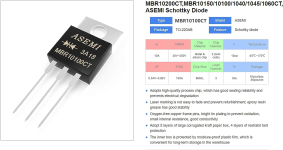
Thanks found this (see image), but wouldn't want to use that particular component due to cost I only had a quick look on ebay to get an idea and they are more money than I spent on both batteries. LOL But I'm sure there are cheaper alternatives.
You can use the 4000 series if you like; it's higher voltage drop and higher power dissipation, harder to heatsink since they typically come in the tiny plastic barrel types rather than something intended to dissipate power.
TBH I hadn't got as far as working out heat dissipation, I realised there would be some. But it's considerably more than I anticipated, a bit of a deal breaker really for the 4000 series diodes.

But then It suddenly occurred to me that there is an easier way to do this with no components at all

As I want to connect two identical 36v 10s batteries in parallel, each having 10 x 2 identical lipo cells. The easiest solution would be put them next to each other, and jumper all the cell groups with decent gauge copper wire, to end up with (in effect) one 36v battery with 10 x groups of 4 lipo pack cells, (and remove one BMS), so its now just one battery with double the mah.

In any event I was going to mount them in a DIY ally box anyway that box made specifically to fit in the bottom of the carrier box below (£18 e-bay already ordered) just so it did not look like a frankenstein monster, and plenty of space left for other junk. Also I was going to add thermostatic control (to box a) with two small louver vents at the front and rear, and a small PC fan at the back vent controlled by the thermo in the third image n case the outer container (box a) trapped heat and got warm. Both powered thru a 12v buck regulator.

What do you think?
 

Attachments

  • Circuit-second-Battery.jpg
    Circuit-second-Battery.jpg
    66.9 KB · Views: 5
  • box a .jpg
    box a .jpg
    44.1 KB · Views: 4
  • thermo.jpg
    thermo.jpg
    115.1 KB · Views: 4
Yeah, you don't need anyehwere near that big a diode. Your controller is what, 10A? 20A? Probably get away with something like these:
random pick from the results
1693249024453.png
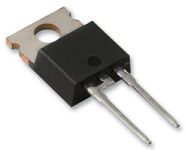
or only like a quarter a piece here
iff you're already buying other stuff to maek the shipping worth it or you have a local farnell / etc with them.
1693249170323.png

You probably even have some of these in the AC-side stages of old PSUs or chargers...


But then It suddenly occurred to me that there is an easier way to do this with no components at all

As I want to connect two identical 36v 10s batteries in parallel, each having 10 x 2 identical lipo cells. The easiest solution would be put them next to each other, and jumper all the cell groups with decent gauge copper wire, to end up with (in effect) one 36v battery with 10 x groups of 4 lipo pack cells, (and remove one BMS), so its now just one battery with double the mah.
Well, yes, that's much simpler, it just doens't give you the option to only use "one" battery (half or whatever of the total). ;)

As for coolling...if the battery or BMS are getting hot enough to need a fan, they're insufficient for the system's load to start with and are likely to age rapidly.

If you want a thermally controlled fan, no need for big complicated electronics, just get a computer case fan that has a thermal sensor built in, and put the sensor where you want it. They're cheap...random google find below, probably plenty of better options
 
Yeah, you don't need anyehwere near that big a diode. Your controller is what, 10A? 20A? Probably get away with something like these:
random pick from the results
View attachment 338899
or only like a quarter a piece here
iff you're already buying other stuff to maek the shipping worth it or you have a local farnell / etc with them.
View attachment 338900

You probably even have some of these in the AC-side stages of old PSUs or chargers...
Yeah they are a more realistic price the one in the diag I found cost a staggering amount.
Well, yes, that's much simpler, it just doens't give you the option to only use "one" battery (half or whatever of the total). ;)

As for coolling...if the battery or BMS are getting hot enough to need a fan, they're insufficient for the system's load to start with and are likely to age rapidly.

If you want a thermally controlled fan, no need for big complicated electronics, just get a computer case fan that has a thermal sensor built in, and put the sensor where you want it. They're cheap...random google find below, probably plenty of better options
Thank you. Not sure of the controller spec, like the other 24v folding bike the controller is built into the frame, and TBH I thought I would leave well alone, as they are a real pain to get out, but I would have guessed at 10A, certainly wouldn't expect it to be over 20A

As just making the two packs into one battery appears so simple, (And as I have 4 of these working) I think that will be an easy relatively risk free option, I only really started thinking of // as an afterthought to save swapping batteries for range, and hoped it might give more current on steep hills. but it has turned out to be a lot more complicated than I expected, And even now I think I have worked out how to do it, there are still grey areas, and its a fair bit of work compared with the one battery approach. I'm not too bothered about losing the ability to use them separately, and in fact cannot see why I would want to. And even if I did the same with another two I would still have two separate batteries (both double the mah they original had). I mention that as that's the only way I could see having two separate batteries as an advantage. one could be at home on charge, while I'm out using the other one.

On the heating issue, I was thinking that the nice looking carrier might trap heat (like wrapping the fin batteries all up in a towel), heat that would otherwise normally be naturally conducted to the ally case, then convected away by passing air. So it was this outer case or pillion box that I was thinking of ventilating. Might be overkill, but I have already ordered the controller in the picture, complete with remote probe £2.70 inc post , and I have loads of old pc fans to choose from, and was actually thinking of small one from video graphics card.

As I got the bits I'll do it anyway, peace of mind. Besides in a worse case scenario, if the battery should burst into flames, at least I should get a jet of flame out the back so the bike will look rocket propelled LOL :ROFLMAO: :ROFLMAO: :ROFLMAO:

K
 

Attachments

  • tempcont.jpg
    tempcont.jpg
    101.5 KB · Views: 1
Last edited:
Thank you. Not sure of the controller spec, like the other 24v folding bike the controller is built into the frame, and TBH I thought I would leave well alone, as they are a real pain to get out, but I would have guessed at 10A, certainly wouldn't expect it to be over 20A
If it's 250w, it's probably a 9 or 10A controller at most.

The diodes just have to be sized for whatever worst-case load they will see; most can handle short surges of much more than their rating if they are adequately heatsinked with enough airflow, but I wouldn't depend on that ability unless it states clearly it can take it for as long as you think you might possibly ever need....

If replacing the controller and wanting to keep similar motor performance, you can google the bike itself to see what wattage it claims, and then divide the watts by the volts to get the current limit it probably had. Or divide the watts it had by the 36v you're going to use to get the current limit you need for the new 36v controller to provide the same output.

If you think the motor/etc can handle the power and you think your usage will draw it, you can use a higher current limit controller.


On the heating issue, I was thinking that the nice looking carrier might trap heat (like wrapping the fin batteries all up in a towel), heat that would otherwise normally be naturally conducted to the ally case, then convected away by passing air. So it was this outer case or pillion box that I was thinking of ventilating. Might be overkill, but I have already ordered the controller in the picture, complete with remote probe £2.70 inc post , and I have loads of old pc fans to choose from, and was actually thinking of small one from video graphics card.

As long as you don't need much airflow and don't mind the noise, the VGC fan might be ok...but the smaller the fan the less air for more noise you get, and almost all small fans use bushings not bearings, so they fail more easily and last less time. You can get better ones, of course.

For heat...I really recommend putting the controllers out in the airflow if you can possibly manage it. If you can't, but can arrange for the FET-side of the controller where they bolt to the case to stick out in the air, taht would be better t han nothing.

IF there's enough airflow from the fan in the case, then that can be even better than having the controllre out in the air with no fan...but it usually isn't, as most people stuff the boxes / bags / etc. tightly enough that there's no room for air to flow freely past the specific things that need that airflow. (airflow design inside things can get complicated when there's a bunch of stuff inside; some things with fans just use loud high volume fans to compensate for that instead of making better airflow).
 
Back
Top