• Howdy! we're looking for donations to finish custom knowledgebase software for this forum. Please see our Funding drive thread

Prismatic 20Ah A123 battery module CAN bus communication

Doctorbass

100 GW
Joined
Apr 8, 2007
Messages
7,496
Location
Quebec, Canada East
I found that the MIT group that work on a fast charging car are working on some A123 battery project and succeded to talk with the A123 battery modules!

that might be intereting for some guys here who ordered some of these 7s3p or 28s3p etc..

The A123 prismatics have a much higher energy density than the 26650's and they come in a sweet pack arrangement. We have some single cells that we've been testing, and Lennon and Shane have built a rig to cycle one prismatic 1,500 times at a 6C charge/discharge rate. More updates on that later.
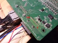
For the past few weeks I've been working on using an Arduino and an MCP2515 chip to talk to the BMS built into the Prismatic Pack. It talks over a CAN network, much like the systems in the Porsche or the elEVen. I've found that using the Arduino allowed me to start communicating in CAN easily in only a day or two, and now I can intelligently talk to the module, polling it for voltage and SOC information and telling it to actively balance itself. In the picture you can see the Arduino board sitting on top of the module, and the cable running over the top that connects the two together. The next step will be to output the battery data to a screen and create a system for talking to multiple packs, like we'll have on the next EVT motorcycle.


see here at the end of the page: http://mit-evt.blogspot.ca/2010_07_01_archive.html

IMG_0068.JPG


Doc
 
Hello ,

Gianni from Italy , I'm working around my ultralight electric motorglider ,
batery pack is A123 28S3P , there are updated information regarding
CAN bus comunication and / or protocol ? .
 
seem to be NOT YET answer.. :?

Doc
 
Hello ,

No any news regarding BMS , I am working with 3 pack in series of 7s3p with foundingpower BMS .


I am looking to sell my Kelly KHB72701C and Ca 120-100 motor because I will change my project from
75Volt BLDC motor to 120Volt motor so i have to buy a HV Kelly


please take a look at :

http://www.ebay.it/itm/141041217144?ssPageName=STRK:MESELX:IT&_trksid=p3984.m1555.l2649

and

http://www.ebay.it/itm/141041220609?ssPageName=STRK:MESELX:IT&_trksid=p3984.m1555.l2649

Saluti

Gianni
 
It's standard CAN. To talk to the board you'd need the CANalyzer config files and Vector CANalyzer (not a cheap tool). Lower level stuff may be possible with cheaper tools, I'm not a CAN specialist. One thing you'd want to be sure of is that the MBB's (Monitor & Balance Boards) are reporting Voltages correctly over CAN--double check the reported values at the weld straps with a good DMM, preferably one that can resolve to 1 mV.

Also be aware that the electronics on the MBB's are very ESD sensitive and you'll want to take care to supply the 12V wakeup signal with a PSU that has a monotonic rise profile. You can blow up the CAN transceiver and isolator if your supply makes any noise on startup.
 
As stated above its standard CAN 2.0B. I've used A123 battery pack systems for a couple projects and never really had any issues talking with them, but I also have all the config files and Vector tools. Unless you have an excessive amount of time on your hands you're going to need the .dbc files to understand whats coming off the CAN bus. Are you trying to talk to the vehicle bus or module bus?

FYI, I've also used Peak CAN tools with some success. A little bit cheaper than the tools from Vector.
 
Hi,

I am currently trying to get the communication working with an arduino and a seedstudio canbus shield, but no success so far.

Does somebody have an idea about pin9 and pin10 of the can connector?

A123Bms.jpg

pin1...VCC
pin2...VCC
pin3...CAN HI
pin4...CAN LO
pin5...CAN LO
pin6...CAN HI
pin7...GND
pin8...GND
pin9...???
pin10...???


I just want to read the actual cell voltages from the module bus.

thanks,
tef
 
Pins 9 and 10 are for sending/receiving fault status. There's nothing there that will help you read voltages. That's reported over CAN.
 
Thank you for clarification.

Should I read any broadcast messages on the bus when the bms is connected?
Could you provide the can messages for reqesting the cell voltages?

tef
 
tef said:
Thank you for clarification.

Should I read any broadcast messages on the bus when the bms is connected?
Could you provide the can messages for reqesting the cell voltages?

tef

Hi,

Sorry, I'm not that good with CAN at this point and don't know the answer to either of these questions. Understand that "VCC" for the board comes from the cells themselves via the larger connector/sense harness. The input voltage on the LV connector is only a wake signal, so both connectors have to be powered for the board to work. Under these conditions, are there messages on the bus from the MBB?
 
I tried again with a can analyze tool and an ixxat usb-to-can device, but there are no messages on the bus.
The communication with the arduino can shield works without problems.

The cells with temp sensors are connected and the 12V enable line (pin1+ and pin7-) is powered from a separate supply.
No changes with a 120 Ohm resistor between CanHI and CanLO.
D76 is blinking and D78 is on permanently.
 
tef said:
I tried again with a can analyze tool and an ixxat usb-to-can device, but there are no messages on the bus.
The communication with the arduino can shield works without problems.

The cells with temp sensors are connected and the 12V enable line (pin1+ and pin7-) is powered from a separate supply.
No changes with a 120 Ohm resistor between CanHI and CanLO.
D76 is blinking and D78 is on permanently.

This is a somewhat older board--D78 is populated with a resistor on newer boards. Sounds like you've got all the connections right. If D76 is blinking slow, the uP is running, but it's not receiving CAN messages. When receiving CAN messages, D76 blinks very fast. If D76 is not lit, the uP isn't running at all. Check that your incoming CAN traffic is making it across the CAN xcvr and isolator chips (IC23 and 19 respectively). Could there be an addressing problem?
 
Just wondering, any success with this? I have been looking at "waking" the BMS on the A123 BAE Hybridrive board, which is for the 12s8p modules. Also seems to be based on a controller with 2 CANBUS interfaces: dsPIC30F6012A.

There's a five pin connector that was used for daisychaining the 16 modules: and a six pin connector that I believe was for the "master" module. The master module communicates with a battery conditioning box.

Wondering where I should apply 5V.. I can see the middle pin of the daisy chain connector (which connects all 16 modules of the pack) is ground, but can't trace anything for the others due to the board coating.
 
Back
Top