Rear Dropout Torque Arms for DH frame?

ryan

10 kW
Joined
Dec 3, 2009
Messages
638
Location
California Bay Area
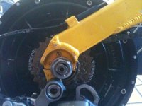
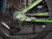
I'm in love with the power of 72V, but unfortunately it's making my dropouts beg for mercy. Can you point me in the right direction for how to get rear dropouts? I've included a few photos, but I'm not really sure what's necessary to either buy rear dropouts or have them custom fabricated.

In this photo you can see that the bolt has moved about 15*. (It should be pointed up toward the nub above it, pretty much 90* to the chainstay. Yes, I have my bolts cranked down HARD with a ratchet.
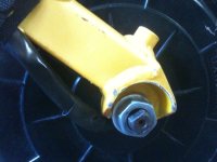
photo-2.jpg

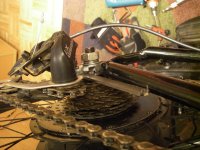
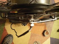
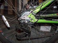
Here's the other side.
photo-3.jpg

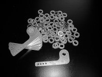
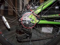
And here's what a dropout might look like.
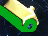
Picture 29.png

Are there vendors that have rear dropouts that would fit this? How would I go about determining if my frame would fit them?

If not, what measurements are important to give someone to have them fabricate a torque arm for me? Any pointers on how to do this? Or photos that would be important to take and diagram out?

Thanks.

(Until they're fabricated I'm staying very low on amp draw to minimize tension on the dropouts... they don't move at all if I'm gentle. It's only when I push it hard from a stop that makes me nervous.)
 
I don't think you should ride at all until you do something about it. Do you really want your rear wheel falling off while you're riding? You've got high power with high torque, and it looks like only the pressure of the nuts is holding it in place.

The torque arm you drew looks pretty good, and with your dropouts effectively gone, you want to go as thick as possible. It doesn't look like you have much axle to work with on the right, so maybe the guy can machine you a new a thicker insert for that side to replace the bolt on piece there. That means on the left you really need to use a strong steel perfectly cut for a tight fit on the axle and as thick as the axle permits.

I like to overdo my dropouts and I don't have the torque you do. My approach would be to just cut off the now worthless dropouts and make prosthetic dropouts out of steel that slide over and bolt to the AL swingarm. Many guys get away with a lot less.

Something else that's probably a good idea, especially for the right side where the axle force is to tighten the nut, would be to modify a box end wrench to clamp or bolt to the underside of the swingarm. Since you don't have much axle on that side, connecting to the nut that can't go tighter should help act as a torque arm.

To me the store bought torque arms may work fine for low powered rigs, but an x5305 at 72v needs significantly more along with a tighter fit on the axle.

John
 
Yeah, picture of accident waiting to happen. Most likely to fit stock torque arm is Ebikes-ca with Justins latest design. A reworked version of one of the ones in the pic, the new version has more ability to reach around awkward stuff on the frame or forks. Probobally have to do a bit of grinding on any of em for that frame though, that's quite a cup there to get around.

But the best stuff I have seen on rears has always been something designed and fabricated just for that frame. Anybody around your place do lazer cutting steel? Take em a prototype pattern in plastic or thin steel?
 
the cycle 9 version could work, but may need grinding. As an alternitive, you might be able to put the torque arms on the inside, between the motor and the dropout. you might have to replace the washers or spread the dropouts some to make it fit.

If you have already had the motor twist and spread the dropouts, you need 2 torque arms. 1 would have been fine before any damage was done, but if the axle isn't a snug fit now, you need 2, and ones that bolt on securely to the frame.
 
Justins torque are designed for FRONT mount only accorging to his site..... Texas electric bike has a torque arm that looks like your drawing i use it on my arrow tadpole...works fine
 
kriskros said:
Justins torque are designed for FRONT mount only accorging to his site..... Texas electric bike has a torque arm that looks like your drawing i use it on my arrow tadpole...works fine

It may have been designed for the front but it works great on my rear dropouts. I take exception to the "only" part as I think it was primarily designed for the front as that is a real problem area. But I don't see any reference to it being unsuitable for the rear.

Gary

******Begin of Edit******
Read further in the thread and you will see I was quite wrong about this. :shock:
******End of Edit******
 
I just mounted my rear wheel with the torque arm inside the frame on one side, due to lots of wear on the softer aluminum dropout from the "narrow shouldered" axle.

That is the weak link of the BMC mounting surface, and needs to be addressed, with a very strong knurled washer to grip the inner dropout. My dropout is not very deep either; another thing to look for in a good frame for rear mount motors.

My alternative was to get a steel frame bike and rebuild the whole thing!!! Still looking....I now have torque arms on both sides and I will test it in the next couple of days to see how it holds.

I also used the washer inside the right side too. I like the amped bikes version torque arm, will get a couple for my 2nd bike.IMGP4201 [Desktop Resolution].JPGIMGP4202 [Desktop Resolution].JPGtorque arm on inside 1.JPGsteel washer on inside.JPG

I will also get some steel screw hose clamps to hold the torque arms in 2 places laterally. That should do it.
 
So I got the torque arms from Ebikes.ca, and they fit great. The problem is that I don't think I thought through the placement well enough. Can I get some help?

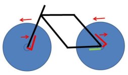
If you look at my draft torque arm (the green example above), you'll notice that the skewer wants to turn clockwise, and the torque arm should hold it in place. But I think if I mount it this way the tension on the torque arm will instead want to pull the skewer out of the frame - based on manually cranking on the bolt to simulate tension.

What do you recommend?
 
Ideally a tourqe arm would be mounted the other way. As you point out, leverage pushing the axle into the dropout is best. If you have enough axle length for it, you might be able to stack washers underneath till the tourqe arm fits the other way.

But getting a good fit of the washers, tourqe arms, and nuts is equally if not more important. Justins tests of fork spinout show how crucial the pressure of the nut on the whole assembly is. I would worry a lot more about the fit of everything than which side the arm attaches on myself.

The dropout is designed for a 9.5 mm radius axle, and now you are putting a much larger radius axle with two 10 mm flat sides on. This makes the radius of the bottom of the dropout too tight for the motor axle. Get out a file, and carefully remove some material from the axle, only on the part the dropout contacts. Leave the threads where the nut goes alone, as well as the area where the tourqe arm goes. This will help the axle seat deeper into the dropout and often will improve the fit of the washers. In some cases, it may be possible to file a dropout deeper. But if you do that, be very carefull not to weaken it any, like leaving a notch from a hacksaw to start a crack.
 
GrayKard said:
kriskros said:
Justins torque are designed for FRONT mount only accorging to his site..... Texas electric bike has a torque arm that looks like your drawing i use it on my arrow tadpole...works fine

It may have been designed for the front but it works great on my rear dropouts. I take exception to the "only" part as I think it was primarily designed for the front as that is a real problem area. But I don't see any reference to it being unsuitable for the rear.

Gary

Gary, are you sure you've got it on the right way? I've had a hard time mounting Justin's torque on the rear, and FYI from this thread.

justin_le said:
GCinDC said:
I've got to confess, I don't understand how those two piece torque arms work... unless they're designed primarily for use w/ front forks.
For the rear, they don't make sense, do they??

Absolutely correct. I designed this torque arm style just over a year ago 100% for use on front forks. It was never intended to work on the rear and no consideration was given to accommodate that. The idea was that if the axle torque cause the torque plate to pivot about the bolt, it would simply sink itself further into the dropout slot. For this to be the case, the torque arm needs to be installed on the back side and not the front side of the fork.

I've seen people attempt to install it on the rear wheel with the torque arm hose clamped to the under side of the chainstays. In this arrangement, the torque plate will tend to rotate the axle OUT of the rear dropout. Not a good setup.

- If I drew up such a design, where could I have it laser cut?
- Or would 1/8 mild steel work fine? I'd be happy to cut that up.

I think we demonstrated pretty clearly that 1/8" steel doesn't cut it for resisting axle spinout torque. Used at least 3/16" or 1/4" metal plate. Most cities will have a facility or two that will do waterjet cutting for you at a reasonable rate.

-Justin
 
I'm back to report that the dropouts are solid now... I added two of Justin's torque arms on the rear and my axel hasn't moved a millimeter. I've been very brutal in testing the torque arms out. Accelerating quickly, pounding it up hills, etc. I've even towed my son in a trailer up a mountain -- the straight way without many curves to take out the grade (the driver of the Bentley I was following up the mountain had the classic confused face as I met him at every stop sign on the way up).

But I think part of the success I'm seeing is due to the big cup I have around my dropout combined with the tension of the nut.

It was helpful to see Justin's comment about the rear torque arms on the thread GCinDC pointed out...

justin_le said:
Absolutely correct. I designed this torque arm style just over a year ago 100% for use on front forks. It was never intended to work on the rear and no consideration was given to accommodate that. The idea was that if the axle torque cause the torque plate to pivot about the bolt, it would simply sink itself further into the dropout slot. For this to be the case, the torque arm needs to be installed on the back side and not the front side of the fork.

I've seen people attempt to install it on the rear wheel with the torque arm hose clamped to the under side of the chainstays. In this arrangement, the torque plate will tend to rotate the axle OUT of the rear dropout. Not a good setup.

So I'd say that my case is likely the exception and more normal dropouts likely won't work.

GCinDC said:
Gary, are you sure you've got it on the right way? I've had a hard time mounting Justin's torque on the rear, and FYI from this thread.
 
ryan said:
So I'd say that my case is likely the exception and more normal dropouts likely won't work.
Glad to hear it's working and battle tested!

Just curious, do you have them below the dropout or above?

Just for academic purposes - and I'm still working out my ideal rear torque arm - so someone correct me if I'm wrong:

If below (as in your green one), then the frame is bracing it. And, if it had to spin out, it would spin down and out of the dropout, rather than up into the dropout.

I see no reason why Justin's concept for the front torque arm wouldn't work for the rear as well (shown in red):
torquearms.jpg
From my limited experience, it's only the actual shape of it that makes it hard to fit rear dropouts...
 
GCinDC said:
GrayKard said:
kriskros said:
Justins torque are designed for FRONT mount only accorging to his site..... Texas electric bike has a torque arm that looks like your drawing i use it on my arrow tadpole...works fine

It may have been designed for the front but it works great on my rear dropouts. I take exception to the "only" part as I think it was primarily designed for the front as that is a real problem area. But I don't see any reference to it being unsuitable for the rear.

Gary

Gary, are you sure you've got it on the right way? I've had a hard time mounting Justin's torque on the rear, and FYI from this thread.

justin_le said:
GCinDC said:
I've got to confess, I don't understand how those two piece torque arms work... unless they're designed primarily for use w/ front forks.
For the rear, they don't make sense, do they??

Absolutely correct. I designed this torque arm style just over a year ago 100% for use on front forks. It was never intended to work on the rear and no consideration was given to accommodate that. The idea was that if the axle torque cause the torque plate to pivot about the bolt, it would simply sink itself further into the dropout slot. For this to be the case, the torque arm needs to be installed on the back side and not the front side of the fork.

I've seen people attempt to install it on the rear wheel with the torque arm hose clamped to the under side of the chainstays. In this arrangement, the torque plate will tend to rotate the axle OUT of the rear dropout. Not a good setup.

- If I drew up such a design, where could I have it laser cut?
- Or would 1/8 mild steel work fine? I'd be happy to cut that up.

I think we demonstrated pretty clearly that 1/8" steel doesn't cut it for resisting axle spinout torque. Used at least 3/16" or 1/4" metal plate. Most cities will have a facility or two that will do waterjet cutting for you at a reasonable rate.

-Justin
Oh, thanks for the link to that thread, had not read it yet! Good info and a cool build.

I see what Justin means about the force wanting to rotate it out of the dropouts if that bolt allows it to pivot. I'll edit my earlier post about this issue. I did not see a warning on the ebikes.ca website about not using those torque arms on the rear but I might have missed it. If it's not there I think it should be addressed.

I did have mine mounted like this:

rear torque arm wrong.jpg
Wrong!

Now I have it mounted like this:

rear torque arm changed.jpg
That should be good now. What do you think?

I wish Justin would work on a version of their torque arms specifically for the rear. :D
 
GrayKard said:
Now I have it mounted like this:

View attachment 1
That should be good now. What do you think?

I wish Justin would work on a version of their torque arms specifically for the rear. :D


Your new way will work, but I see a problem. If the bolt slips the torque arm won't be able to do anything. And the way it's sitting, the torque arm has nothing to push against the bolt with, except the open adjustment slot.

But I also see a fairly simple solution. were the bottom of the slot is in the first half of the torque arm over laps part of the hole for a hose clamp in the second half. another hole could be drilled there and a second bolt added. that would make the arm more secure, and also change the way it works. The blue arrow is how force would be applied to the upper arm and hose clamp now. the orange arn is how force would be applied with the second bolt. the second way would have less chance of slipping
 

Attachments

  • rear torque arm changed copy.jpg
    rear torque arm changed copy.jpg
    44 KB · Views: 998
Drunkskunk said:
GrayKard said:
Now I have it mounted like this:

View attachment 2
That should be good now. What do you think?

I wish Justin would work on a version of their torque arms specifically for the rear. :D


Your new way will work, but I see a problem. If the bolt slips the torque arm won't be able to do anything. And the way it's sitting, the torque arm has nothing to push against the bolt with, except the open adjustment slot.

But I also see a fairly simple solution. were the bottom of the slot is in the first half of the torque arm over laps part of the hole for a hose clamp in the second half. another hole could be drilled there and a second bolt added. that would make the arm more secure, and also change the way it works. The blue arrow is how force would be applied to the upper arm and hose clamp now. the orange arn is how force would be applied with the second bolt. the second way would have less chance of slipping

I think the force on it would be more like this:
rear torque arm force.jpg

If the torque arm was allowed to spin then the bolt would try to follow the red circle. That would put the force almost perpendicular to the slot. Since the other part is pressed against the frame along most it's length it would try to move the other end along the line and not down the length of the second piece.

So if the second piece is secured properly and does not move then the axle will be forced harder up into the dropout. I hope...
 
Back
Top