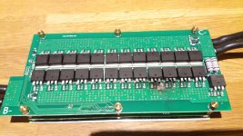
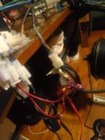
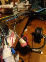
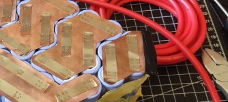
Sabvoton SVMC 72150 doesn't do full power

larsb said:
minde28383 said:
I have installed quite a few ant 20s bmses. They have amp limiting feature and if set accordingly they do limit power overall. So it could easily be the bottleneck but I too leaning towards battery because you checked bms settings and they are maxed I assume. Usually when people want high outputs we expect about 7p or even more parallel, with 2100 cells it could be few less parallel but 4p is on low side even if your specific cells have good specs. Their connections matters much too, specifically on high load.

You can set discharge current limit in the ant bms but does it really limit amps to this value? Do you have proof of this? I have run my ant bms up to 300A when set this high so there’s no general limitation.

I don’t think any bms really limits the current at a certain level, it cuts current to protect, limiting will be done by the controller.

Never thought so much about terminology of these words: limit, general limit to value, cut current to protect.
Never thought about that too much because usually all maxed and it it works, but it makes sense what you wrote. Now i believe that there is no such active limiting by bms but only cut to protect when limit reached.
 
I mean, how much more is there to adjust? The Ant records some data, no? I thought they might have... You got the bike, you got the system, it is in and working, just not enough power off the line. I have spoken with some old experienced Sabvoton users and they all say they will / can pull 140+/- A on accelerations and sit at continuous loading of about 120A+/-.

Accel/decell time set to 20/30? That is how I set mine, and it did improve performance off the line. That is another question... are you absolutely sure you get full analog throttle actuation? Yes, set for 1-4v in the program.. but you DO get your full 4v at full throttle application? Analog? Perhaps the throttle has a fluke and is only allowing 2.8v... 3.2v.. to the throttle and the controller is never in position to demand full current? Perhaps the throttle has a fluke and cannot output full signal voltage? Measure under power to include any flukes in the system during test.. I have had throttle that test fine on the bench but when hooked up they do funny things.

Yes is certain a mystery... If you have confidence, I understand. IN the power handling of the pack. We know the IR of the cells in question.. from the data... We know the group IR and we can figure the Vdrop from that... within math...

Vd=xS/xP*Rc*I
"You will get your Voltage drop by number of series cells divide by number of parallel cells times average cell resistance in ohms time current draw in amps."

Dont forget the real world performance factor.. all busbars are not perfect busbars, wires have resistance, and the final product of that calculation above does not reflect that ( real world scenario)... But should get us close and give us an idea of a loaded Vdrop.

Sparfuchs said:
And I chose this bms because it was the only 19s! bms with this current.

I have been using a BMS that can do 200A, also has a huge heat sink included. Long and thin, as opposed to the Ant.

If you hold interest. It can do 6s-20s, Lion or lifepo.

https://www.lithiumbatterypcb.com/product/6s-to-20s-li-ion-or-lifepo4-smart-bms-with-150a-or-200a-constant-current/
 
DogDipstick said:
...they all say they will / can pull 140+/- A on accelerations and sit at continuous loading of about 120A+/-.

Accel/decell time set to 20/30? That is how I set mine, and it did improve performance off the line.
I have thre SVMC72150 in my 180kg scooter.either with a QS60V5000W or with an Erider 8kW Motor.
Battery has 13milliiohm resistance at the controller screws.
My first Sabvoton gave 150A all the time I want, until it gets to warm. It gives my 10kw for 20minutes continously without any issues. But it died while plying with the weakening fiel parameters.
The second one, the one I have installed now makes up to 175A DC without any issues, this one is not unlocked but the curent setting was not done right during production. It always give around 15% more DC-current than set in the software.

I also had installed a ANT 150/300A BMS and had no power or overheating issues during driving, but I added a small heat sink to it before I installed it.
It was running good with 3 mosfets less , because three of them died, when my SVMC72260 died, while I played with field weakening.

20201107_193816.jpg
 
larsb said:
I don’t think any bms really limits the current at a certain level, it cuts current to protect, limiting will be done by the controller.
Correct. The only thing a BMS can do is cut all output, or not cut any output, based on whatever settings it has.

For a BMS to do current limiting without doing this, it would have to be designed the way a brushed controller or current-limiting PSU/charger is, and would be as large as either one is when providing the wattage one of the PSU/chargers does. (meaning, a true current-limiting BMS for a 10kw system would be as large as a 10kw PSU/charger that does the same job, as it would then be doing that job in the same way).
 
So if the bms can't limit the current, I assume the bms can't be my problem because the battery never did cut/disconnect at full throttle ?

Another thing I haven't seen as worth mentioning for now is that I get a different voltage on my blue hall wire.
So if i disconnect the motors hall connector and measure at the controllers hall plug I get from +5V to GND about 4,69V. But if i measure from GND to yellow, green and blue I get about 3,05V, 3,05V and 6,3V(blue). But as the controller is new and the hall check with the motor halls connected got me the results when slowly spinning the wheel: 0v/3,05v, 0v/3,05v and 0v/6,3v I assumed the halls work fine and that this is just the way the sabvoton works. Is that normal ?
 
Sparfuchs said:
So if the bms can't limit the current, I assume the bms can't be my problem because the battery never did cut/disconnect at full throttle ?

Another thing I haven't seen as worth mentioning for now is that I get a different voltage on my blue hall wire.
So if i disconnect the motors hall connector and measure at the controllers hall plug I get from +5V to GND about 4,69V. But if i measure from GND to yellow, green and blue I get about 3,05V, 3,05V and 6,3V(blue). But as the controller is new and the hall check with the motor halls connected got me the results when slowly spinning the wheel: 0v/3,05v, 0v/3,05v and 0v/6,3v I assumed the halls work fine and that this is just the way the sabvoton works. Is that normal ?

it should not be like that asfaik. Simple test. Connect voltmeter to you batt. Give full throttle, on some steep road sand etc yo have at your area, prolong the load so that could see voltage change, what batt voltage sag? Initial voltage - voltage drop on max load you can achieve = sag you get on your battery. If you can charge up your batt before this simple test.
 
Sparfuchs said:
So if the bms can't limit the current, I assume the bms can't be my problem because the battery never did cut/disconnect at full throttle ?

Another thing I haven't seen as worth mentioning for now is that I get a different voltage on my blue hall wire.
So if i disconnect the motors hall connector and measure at the controllers hall plug I get from +5V to GND about 4,69V. But if i measure from GND to yellow, green and blue I get about 3,05V, 3,05V and 6,3V(blue). But as the controller is new and the hall check with the motor halls connected got me the results when slowly spinning the wheel: 0v/3,05v, 0v/3,05v and 0v/6,3v I assumed the halls work fine and that this is just the way the sabvoton works. Is that normal ?

i never doubted these voltages to differ at all. Mine differs little bit fir far drive ND controller too but not so much like on your sabvoton. It will bother your and won't find result about that 6.3v on yours.. i have got new sabvoton, i could test but probably in few days time. I did such test like you but on ND far drive controller and results: 3.06v, 3.02v, 2.79v.
 

Attachments

  • IMG20230120201522.jpg
    IMG20230120201522.jpg
    22.6 KB · Views: 88
DogDipstick said:
.... set for 1-4v in the program.. but you DO get your full 4v at full throttle application? Analog? Perhaps the throttle has a fluke and is only allowing 2.8v... 3.2v.. to the throttle and the controller is never in position to demand full current? Perhaps the throttle has a fluke and cannot output full signal voltage? Measure under power to include any flukes in the system during test.. I have had throttle that test fine on the bench but when hooked up they do funny things.
....

and follow clarify this cause you never know till you check.
 
Remember the motor halls don't output any voltage, they just ground the pullups in the controller whenever they are turned on (open-collector output).

This means that without the controller connected to the motor, there is no valid reading for the hall signals from the motor.

To test them, the controller must be connected to the motor and the controller must be powered on and active. Or else you must use a test setup of a resistor from the hall signal under test to the hall supply voltage (typically a 9v battery can be used for this, if you are not powering the halls from the motor, most halls can use up to 20-30v for their supply and signal pullup voltages).

If just testing the hall pullups on the signal inputs at the controller, those will be valid with or without the motor connected, and should read the same as the pullup supply voltage (which can be different than the hall power supply voltage; requires opening the controller and tracing the signal line to the pullup resistors to see what they are powered from).

If there is a different voltage on one of these, without the motor connected, there is something "wrong" in the controller with that specific pullup line. (or else, it's fine and the other two have a problem).


Those pullups generally go to 5v, but some controllers use a higher voltage, as that provides a higher signal-to-noise ratio, which helps reading the hall signals with all the noise induced from the motor phase currents.

For 5v pullups, normally you'll see that on each of the signals at any point in the cable all the way to the sensor signal lead, whenever the sensor is off. When the sensor is on, then at the controller end of the cable the voltage may read higher than at the sensor end, but not by much as the OC output of the halls can only ground a small current (couple dozen mA or so, typically), so even a little higher than normal resistance in the cable/connector shouldn't have much effect on the voltage drop.

If the controller uses 12v or some other voltage for the pullups, the same applies.

It could use 3v (or 3.3v) if it has a supply for that, such as to power a 3.3v MCU/etc, but it seems unusual to have as low as ~3v as pullup; it would not give a very good signal to noise ratio for the hall signal (whcih makes it more vulnerable to induced phase current noise).

Unless the controller uses a voltage divider on the 12v to get the ~6v, it would be unusual to ahve that voltage as the pullup voltage, as there's nothing typically in there that would be powered by 6v, and seems odd to have a supply just for the pullups for that voltage.
 
amberwolf said:
..
This means that without the controller connected to the motor, there is no valid reading for the hall signals from the motor.

To test them, the controller must be connected to the motor and the controller must be powered on and active.
..

I assume he did that way, otherwise who knows how he tested
''1 hall connector'' hall connected to controller, ''2 hall connector'' for measuring voltages. Applying throttle, measuring. I did via second because easier to access terminals.
All this testing is for curiosity :) As I initially suspected I still think the same, too weak too small battery.
 

Attachments

  • IMG_20230120_225652.jpg
    IMG_20230120_225652.jpg
    21.8 KB · Views: 68
minde28383 said:
amberwolf said:
..
This means that without the controller connected to the motor, there is no valid reading for the hall signals from the motor.

To test them, the controller must be connected to the motor and the controller must be powered on and active.
..

I assume he did that way, otherwise who knows how he tested
''1 hall connector'' hall connected to controller, ''2 hall connector'' for measuring voltages. Applying throttle, measuring. I did via second because easier to access terminals.
All this testing is for curiosity :) As I initially suspected I still think the same, too weak too small battery.
I'm not an expert, but I do know that electricity is not transmitted by magic or hope... so no, I did not try to check the hall sensors without any connection to them :D
 
thanks to the hint that a 6v hall signal isn't normal I searched and found the reason.

So what i did was to check the halls (of course first connected to the powered on controller) and had as mentioned from gnd to +5V about 5v, fine, and from gnd to the colors by slowly spinning the wheel: 0v/3,05v, 0v/3,05v and 0v/6,3v. As the 6,3 seemed unusual to me I got curious an checked the hall plug without the plug of the motor and got from GND to yellow, green and blue about 3,05V, 3,05V and 6,3V(blue). As I didn't know better, the fact that the 6V on blue comes from the controller I assumed the motors halls are fine and got to the wrong conclusion thats just the way the controller works.

To disclose the "secret": the problem was caused by connecting the hall meter wire of the sabvoton to the speed hall connection of my cycle analyst. When its disconnected all hall signals are as the should !

The reason why i took the hall meter for the speed of the c.a. because I knew that you usually take any of the hall wires and connect the speed of the c.a. in parallel to it and I thought maybe that's exactly what the hall meter wire does. And as I checked I had continuity to the blue hall wire for the sensors and also the exact same behavior with the hall test. Opening it up showed that the hall meter is really just soldered to the blue hall sensor wire.

So my conclusion is that the c.a. has a voltage on it's speed wire and whatever hall I connect it to, it doubles it's voltage.
As my hall angle test results and all the performance is the exact same with the hall meter disconnected it doesn't seem to be a problem or the solution to my problem I guess
 
minde28383 said:
amberwolf said:
..
This means that without the controller connected to the motor, there is no valid reading for the hall signals from the motor.

To test them, the controller must be connected to the motor and the controller must be powered on and active.
..

I assume he did that way, otherwise who knows how he tested
''1 hall connector'' hall connected to controller, ''2 hall connector'' for measuring voltages. Applying throttle, measuring. I did via second because easier to access terminals.
All this testing is for curiosity :) As I initially suspected I still think the same, too weak too small battery.
Although I haven't ever tried a bigger battery to have a comparison, doesn't your thought mean that if a 19s4p battery pack can't do more than absolute max 80amps, that the pulse/burst limit of the samsung 40T would be 20amps and it should get at least warm ?
I really appreciate to get corrected if I got something wrong, but if one cell of them can handle in tests 70amps for a few seconds (before getting hot), 45amps for quite a while before getting to warm, and 35amps for continuous without getting warm, there is no plausible explanation to me why a ice cold of those cell should haven gotten to it's limit at 20amps in a pack ?
I got the cells from the biggest seller in Europe, but even if he would have sold me worst resistance fake cells, I guess they would still get hot or at least warm if I've really pushed them to their limit ?
 
Sparfuchs said:
..., there is no plausible explanation to me why a ice cold of those cell should haven gotten to it's limit at 20amps in a pack ?
I got the cells from the biggest seller in Europe, but even if he would have sold me worst resistance fake cells, I guess they would still get hot or at least warm if I've really pushed them to their limit ?
If they are ice cold they have more internal resistance and you get more voltage drop under load.
Ifcthey get wärmer resistance gets lower and you can get less sag and more amps from the batteries.
That's the reason why the preheat the batterie for e-dragsters.

Cells eith high resistance eould get hot when you misteeat them.
 
Just in case it comes up as an plausible reason. I really did all I could to keep the resistance of all the components of the pack as low as possible to get the max out of the cells. All that work would have been for nothing if only 80amps pass them 1674315096102.jpg
 
All this sounds good and true but it does not work as should therefore have you tested with throttle fully open and checked battery pack voltage drop? This is so simple test.
 
dominik h said:
Sparfuchs said:
..., there is no plausible explanation to me why a ice cold of those cell should haven gotten to it's limit at 20amps in a pack ?
I got the cells from the biggest seller in Europe, but even if he would have sold me worst resistance fake cells, I guess they would still get hot or at least warm if I've really pushed them to their limit ?
If they are ice cold they have more internal resistance and you get more voltage drop under load.
Ifcthey get wärmer resistance gets lower and you can get less sag and more amps from the batteries.
That's the reason why the preheat the batterie for e-dragsters.

Cells eith high resistance eould get hot when you misteeat them.
Well, ice cold was a bit have a exaggerated to emphasize that they were far away from getting hot...my fault. It's about 0 degrees celcius here in Austria at the moment but I store the pack at room temperature and don't think a few minutes for testrides outside influences the pack :)
 
What happens when you activate flux weakening? Do you see more DC-curent?

Mine took 150A at full speed 110p/h with flux weakening activated
Without flux weakening DC-current dropped to 90-100A at 103kp/h.

Do not run the motor unloaded with flux weakening activated.
I killed a 72150 and a 72260 during no load tests.
 
Perhaps you have the wrong firmware on your sabvoton. Can you measure phase current?
 
minde28383 said:
All this sounds good and true but it does not work as should therefore have you tested with throttle fully open and checked battery pack voltage drop? This is so simple test.
Well unload of course: popping full throttle gets a Voltage drop from 78,5 to 77,7 (0,8v) for half a second and if it stays in top speed it's drop is about 0,3V.

As I primary focused at the drawn amp/watt on the c.a. screen I don't know for sure if I checked but I guess I would have noticed if the drop was quite significant.. but who knows. I'll deferentially check asap and report
 
Sparfuchs said:
minde28383 said:
All this sounds good and true but it does not work as should therefore have you tested with throttle fully open and checked battery pack voltage drop? This is so simple test.
Well unload of course: popping full throttle gets a Voltage drop from 78,5 to 77,7 (0,8v) for half a second and if it stays in top speed it's drop is about 0,3V.

As I primary focused at the drawn amp/watt on the c.a. screen I don't know for sure if I checked but I guess I would have noticed if the drop was quite significant.. but who knows. I'll deferentially check asap and report

You got mxus turbo so called 3kw hub in 24"" wheel, i assume it is 9kv torque wound it is not power hungry because it is low kv instead 11 or 13 as it could be. Whats your weight? Whats ebike weight? Maybe everything is very light and you get instantly hight rpm and running and it does not need more power, can't take more power. You mentioned voltage drop is suspiciously small and would call even neglegible. Must be way bigger voltage sag or there actually is something preventing these amps "flowing".
 
Oh I see, these unloaded voltage drop thats why so small drop. Well let's see loaded V drop. I expect unfortunately it to be very many more volts due too few parallel cells.
 
Back
Top