You are using an out of date browser. It may not display this or other websites correctly.
You should upgrade or use an alternative browser.
You should upgrade or use an alternative browser.
Smart EBike: Dashboard + Motor controller + Battery BMS
- Thread starter casainho
- Start date
casainho
10 GW
- Joined
- Feb 14, 2011
- Messages
- 6,047
You are correct, thanks. I will put them.h0tr0d said:I don't see any bus capacitors, better put some...
Obrigado. Eu sou de Águeda/Aveiro. Cumprimentos.h0tr0d said:Fui eu que não os vi, ando cegueta, ou só não estão no esquema? Tema muito importante!
Boa sorte com o projecto e cumprimentos Lisboetas! :wink:
casainho
10 GW
- Joined
- Feb 14, 2011
- Messages
- 6,047
I bought a new bicycle and a new Cute85/Q85 24V 250W, for testing the controller. I don't want to test the controller on my current 48V electric bicycle, I need it working perfectly for my use.
The new bicycle were I will install the new motor on front wheel:
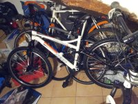
And the new motor Cute85/Q85 24V 250W:

I just found some videos about the production of a electric bicycle on China, is great to see on the video the motor I used (Bafang 500W). Great to see how they make the motors!! A LOT of electric bicycles on China!!!
[youtube]afOsj9t_kgY[/youtube]
[youtube]3vToXcsqgms[/youtube]
More videos here.
The new bicycle were I will install the new motor on front wheel:

And the new motor Cute85/Q85 24V 250W:
I just found some videos about the production of a electric bicycle on China, is great to see on the video the motor I used (Bafang 500W). Great to see how they make the motors!! A LOT of electric bicycles on China!!!
[youtube]afOsj9t_kgY[/youtube]
[youtube]3vToXcsqgms[/youtube]
More videos here.
Attachments
h0tr0d
1 kW
- Joined
- Apr 28, 2012
- Messages
- 460
casainho said:- 6 PWM channels (2 for each phase) to drive mosfets --> drive each phase
-- 3 for measure a voltage related to current of each phase
Why 6 pwm, since you only need 3?
with only 2 phase current sensors you can measure the phase current of all 3 phases...
Probably for synchronous rectification (much higher efficiency, much less heat).h0tr0d said:Why 6 pwm, since you only need 3?
Yup It will help save the diodes inside the fets among other things.Njay said:Probably for synchronous rectification (much higher efficiency, much less heat).h0tr0d said:Why 6 pwm, since you only need 3?
casainho
10 GW
- Joined
- Feb 14, 2011
- Messages
- 6,047
Prototype 2 works. Photos recorded on 25.12.2012:


Vídeo recorded on 25.12.2012:
[youtube]trihb86_mnw[/youtube]
There is a problem seen after 00:50, about after 75% of throttle. The lab power supply starts to cut and can be seen that the power supply voltage increases from 20.8V to 21.5V as also a current increase. Does anyone have an idea why this happen?
All the info on Prototype 2 page: http://smartebike.likesyou.org/doku.php/prototype_2
h0tr0d
1 kW
- Joined
- Apr 28, 2012
- Messages
- 460
Arlo1 said:Yup It will help save the diodes inside the fets among other things.Njay said:Probably for synchronous rectification (much higher efficiency, much less heat).h0tr0d said:Why 6 pwm, since you only need 3?
keep forgetting the diodes are there...
Maybe the motor is injecting current into the big caps through the MOSFET diodes? Maybe your commutation sequence gets confused because of the current limiting caused by the power supply and it stops handling the re-circulation current properly? Who knows; but you have the device and the measuring toolscasainho said:There is a problem seen after 00:50, about after 75% of throttle. The lab power supply starts to cut and can be seen that the power supply voltage increases from 20.8V to 21.5V as also a current increase. Does anyone have an idea why this happen?
casainho
10 GW
- Joined
- Feb 14, 2011
- Messages
- 6,047
The power supply should handle the load since this problem happens as seen on the video, no load. The power supply handles 10A.Njay said:Maybe the motor is injecting current into the big caps through the MOSFET diodes? Maybe your commutation sequence gets confused because of the current limiting caused by the power supply and it stops handling the re-circulation current properly? Who knows; but you have the device and the measuring toolscasainho said:There is a problem seen after 00:50, about after 75% of throttle. The lab power supply starts to cut and can be seen that the power supply voltage increases from 20.8V to 21.5V as also a current increase. Does anyone have an idea why this happen?. It may just be an "insufficient current issue" that you should disregard; try a power supply that can handle the load. Otherwise I would start by checking if the 21.5V are constant.
I took some hours but I couldn't yet find the problem origin.
Here, with voltage supply of about 18V, the problem happens when voltage starts to drop (with PWM pulses) and finally it raises quickly. The same happens with supply voltage of 20V or 24V, as I tested before.
View attachment NewFile55.bmp
Zoom in of last image:
View attachment NewFile56.bmp
And working correctly at "medium" throttle:
View attachment NewFile46.bmp
Zoom in of last image:
View attachment NewFile44.bmp
Zoom in of last image:
View attachment NewFile45.bmp
And at maximum throttle/speed (were without catching the problem):
View attachment NewFile0.bmp
Does it happen if you hold the throttle steady at those 75% where you see it? Even without load, when you speed up, the acceleration will raise current consumption until the speed "catches up" with the throttle. The faster you speed up the more current it will pull until the speed catches up.
casainho
10 GW
- Joined
- Feb 14, 2011
- Messages
- 6,047
I looked at power supply line and you are correct, the power supply line drops a lot on the PWM changes/ringing. I had changed the mosfets gate resistor from 10R to 100R and I got a better system but not good yet. I changed again to 470R and it is perfect BUT rise/fall times of PWM are now 1us!!! which seems bad...Njay said:Does it happen if you hold the throttle steady at those 75% where you see it? Even without load, when you speed up, the acceleration will raise current consumption until the speed "catches up" with the throttle. The faster you speed up the more current it will pull until the speed catches up.
Even with 470R gate resistors, I see power supply line drop a lot on acceleration... maybe I need to controller better the power/current ramp. Or maybe I need more/better capacitors...
Thank you NJay!
And/or make sure you are really limiting the current.casainho said:Even with 470R gate resistors, I see power supply line drop a lot on acceleration... maybe I need to controller better the power/current ramp. Or maybe I need more/better capacitors...
If your power supply line drops a lot then your power supply is likely not enough voltage. You can try to add more caps but I have ran into issues with power supplies feeding my controller as well. I usually get it running a bit then switch to a battery for testing with a fuse or circuit breakercasainho said:I looked at power supply line and you are correct, the power supply line drops a lot on the PWM changes/ringing. I had changed the mosfets gate resistor from 10R to 100R and I got a better system but not good yet. I changed again to 470R and it is perfect BUT rise/fall times of PWM are now 1us!!! which seems bad...Njay said:Does it happen if you hold the throttle steady at those 75% where you see it? Even without load, when you speed up, the acceleration will raise current consumption until the speed "catches up" with the throttle. The faster you speed up the more current it will pull until the speed catches up.
Even with 470R gate resistors, I see power supply line drop a lot on acceleration... maybe I need to controller better the power/current ramp. Or maybe I need more/better capacitors...
Thank you NJay!
casainho
10 GW
- Joined
- Feb 14, 2011
- Messages
- 6,047
Thanks. What do you prefer, fuse or circuit braker? I would like to get your opinion/knowledgeArlo1 said:If your power supply line drops a lot then your power supply is likely not enough voltage. You can try to add more caps but I have ran into issues with power supplies feeding my controller as well. I usually get it running a bit then switch to a battery for testing with a fuse or circuit breaker
I bought a header board with STM32F100 for $12.5. It have 48 pins LQFP and runs at 24MHz. I don't know if this ARM 32bits Cortex-M3 at 24MHz will be ok, if not I will jump to STM32F103 that runs at 72MHz.
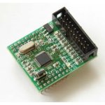
I decided to try STM32F100 because it is cheaper than a PIC/AVR but is much more powerful, it also have specific hardware for motor control plus STM provides a STM32 FOC PMSM library and application notes. Also important for me is that development tools are OpenSource (programmer and debugger) and they work very well on Linux
The LPC2103 I am using is old ARM7, it needs 3.3V and 1.8V power supplies (while STM32F10x only needs 1 of 3.3V). STM32F100 have PWM complementary for synchronous rectification while LPC2103 doesn't. Also LPC2103 ADCs are only 10 bits while STM32F100 have 12 bits ADC and also a 12 bits DAC.
casainho
10 GW
- Joined
- Feb 14, 2011
- Messages
- 6,047
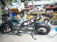
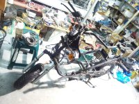
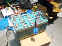
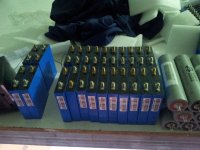
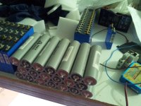
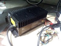
A bit out of topic, but since I am also interested on Ebikes/scooters and as this controller may work for them in future. I took this pictures at local garage of a person.
EBike mechanical structure:
Different battery cells:
View attachment 4
This cells holds 60Ah!!
View attachment 3
And a charger:
EBike mechanical structure:


Different battery cells:

View attachment 4
This cells holds 60Ah!!
View attachment 3


And a charger:

casainho
10 GW
- Joined
- Feb 14, 2011
- Messages
- 6,047
I started to make the procurement of a metal enclosure for the controller, so it can be used as enclosure and also as a heat sink (just like the chinese ones do, like on KU63 controller). I JUST FOUND on Ebay the exact aluminum enclosure used on KU63 controllers and alike 
Now I just need to find a standard size and use it to design the controller PCB
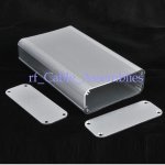
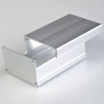
Now I just need to find a standard size and use it to design the controller PCB


casainho
10 GW
- Joined
- Feb 14, 2011
- Messages
- 6,047
I started to work on prototype V3. the main changes are:
- move from ARM7 32 bits LPC2103 to ARM Cortex-M3 32 bits STM32F100 (this one have specific hardware for BLDC motor control)
- use a 10000uF capacitor and 4 ceramic 10uF capacitors on power line (to avoid the ringing problem on the circuit)
- change the 5V voltage regulator to the other LM1117MP-5.0 (the other one were getting hot)
- put the mosfets vertical aligned so I can screw them to aluminum enclosure for dissipation
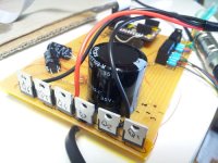
The STM32F100 header board is still to arrive by mail but I already put the new capacitors on the circuit and aligned the mosfets. The new capacitors give good results!! Here a picture of current prototype 3 board:

Attachments
casainho
10 GW
- Joined
- Feb 14, 2011
- Messages
- 6,047
I received the STM32F100 header board and I got the first firmware working for it. I started to use a blinky firmware example from Martin Thomas, many thanks to him!!
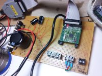
After the LED blink, the very first thing I put working were the Throttle signal, that is measured by ADC and the DMA controller put it directly to a variable on SRAM -- there is no intervention from the CPU. This is the first time I am using a DMA controller
STM32 have many application notes, drivers and firmware examples, that's how I got so quickly the ADC DMA working.
The STM32F100 also have an ADC WatchDog, were I can configure the max value for ADC and I get an interrupt (or a trigger for other things) if ADC values goes over the max value. I plan to use this for MAX motor current control, were the ADC WatchDog will work like a kind of a comparator for detect the max motor current and disable the duty_cycle on PWM cycle.
The connections to STM32F100 will be:
* PA0 (ADC1_IN1) -- throttle signal (Use DMA here)
* PA1 (ADC1_IN2) -- voltage signal (Use DMA here)
* PA2 (ADC1_IN3) -- current signal (Use DMA and ADC WatchDog here)
* PA3 (ADC1_IN4) -- temperature signal (Use DMA here)
* PB12 (TIM1_BKIN) -- brake signal (Use the Timer1 Emergency/Brake Signal for PWM disable)
* PA8 (TIM1_CH1) -- PWM 1
* PA9 (TIM1_CH2) -- PWM 2
* PA10 (TIM1_CH3) -- PWM 3
* PB13 (TIM1_CH1N) -- PWM 4 (Complementary PWM 1 with dead time)
* PB14 (TIM1_CH2N) -- PWM 5 (Complementary PWM 2 with dead time)
* PB15 (TIM1_CH3N) -- PWM 6 (Complementary PWM 3 with dead time)
* PA6 (TIM3_CH1) -- Hall sensor 1 (Use the digital filter and Hall Sensor XOR pheripherial)
* PA7 (TIM3_CH2) -- Hall sensor 2 (Use the digital filter and Hall Sensor XOR pheripherial)
* PB0 (TIM3_CH3) -- Hall sensor 3 (Use the digital filter and Hall Sensor XOR pheripherial)
* PB10 (USART3_TX) -- UART TX Bluetooth module (Use DMA here)
* PB11 (USART3_RX) -- UART RX Bluetooth module (Use DMA here)

After the LED blink, the very first thing I put working were the Throttle signal, that is measured by ADC and the DMA controller put it directly to a variable on SRAM
STM32 have many application notes, drivers and firmware examples, that's how I got so quickly the ADC DMA working.
The STM32F100 also have an ADC WatchDog, were I can configure the max value for ADC and I get an interrupt (or a trigger for other things) if ADC values goes over the max value. I plan to use this for MAX motor current control, were the ADC WatchDog will work like a kind of a comparator for detect the max motor current and disable the duty_cycle on PWM cycle.
The connections to STM32F100 will be:
* PA0 (ADC1_IN1) -- throttle signal (Use DMA here)
* PA1 (ADC1_IN2) -- voltage signal (Use DMA here)
* PA2 (ADC1_IN3) -- current signal (Use DMA and ADC WatchDog here)
* PA3 (ADC1_IN4) -- temperature signal (Use DMA here)
* PB12 (TIM1_BKIN) -- brake signal (Use the Timer1 Emergency/Brake Signal for PWM disable)
* PA8 (TIM1_CH1) -- PWM 1
* PA9 (TIM1_CH2) -- PWM 2
* PA10 (TIM1_CH3) -- PWM 3
* PB13 (TIM1_CH1N) -- PWM 4 (Complementary PWM 1 with dead time)
* PB14 (TIM1_CH2N) -- PWM 5 (Complementary PWM 2 with dead time)
* PB15 (TIM1_CH3N) -- PWM 6 (Complementary PWM 3 with dead time)
* PA6 (TIM3_CH1) -- Hall sensor 1 (Use the digital filter and Hall Sensor XOR pheripherial)
* PA7 (TIM3_CH2) -- Hall sensor 2 (Use the digital filter and Hall Sensor XOR pheripherial)
* PB0 (TIM3_CH3) -- Hall sensor 3 (Use the digital filter and Hall Sensor XOR pheripherial)
* PB10 (USART3_TX) -- UART TX Bluetooth module (Use DMA here)
* PB11 (USART3_RX) -- UART RX Bluetooth module (Use DMA here)
casainho
10 GW
- Joined
- Feb 14, 2011
- Messages
- 6,047
Current status of prototype 3:
- I have now the 4 ADC signals (voltage, current, throttle, mosfets temperature) measured automatically (without CPU intervention) and with DMA
- the PWM signal is also working, with the duty_cycle setup by the ADC throttle signal. Also the 6 steps commutation works
- now is missing the Hall sensor code, current control and brakes code
The STM32 have this hardware specific to BLDC control:
"Clearing the OCxREF signal on an external event (for current control)
For example, the OCxREF signal) can be connected to the output of a comparator to be
used for current handling. "
"Analog watchdog (I hope to use it for current control)
The AWD analog watchdog status bit is set if the analog voltage converted by the ADC is
below a low threshold or above a high threshold. These thresholds are programmed in the
12 least significant bits of the ADC_HTR and ADC_LTR 16-bit registers. An interrupt can be
enabled by using the AWDIE bit in the ADC_CR1 register."
"Six-step mode (6 step BLDC)
The six step mode is a specific mode of STM32 advanced timers. When complementary
outputs are used on a channel, preload bits are available on the OCxM, CCxE and CCxNE
bits. The preload bits are transferred to the shadow bits at the COM (commutation event).
Thus you can program in advance the configuration for the next step and change the
configuration of all the channels at the same tim",
"How to use the Hall sensor interface (hall sensor inputs with programable digital filters)
The STM32 timers can interfaces with the Hall effect sensors via the standard inputs (CH1,
CH2 and CH3). Setting TI1S bit in the CR2 register, allows the input filter of channel 1 to be
connected to the output of a XOR gate, combining the three input pins TIMx_CH1,
TIMx_CH2 and TIMx_CH3."
"Break input (I hope to use it for brakes)
The break input is an emergency input in the motor control application. The break function
protects power switches driven by PWM signals generated with the advanced timers."
casainho
10 GW
- Joined
- Feb 14, 2011
- Messages
- 6,047
Current status of prototype 3:
- the 4 ADC signals (voltage, current, throttle, mosfets temperature) measured automatically (without CPU intervention) and with DMA.
- the PWM signal is working, with the duty_cycle setup by the ADC throttle signal.
- Hall Sensors are working using the STM32F100 specific hardware for this
- the 6 steps commutation works
Missing:
- current control (maybe it's needed to put a comparator on the circuit)
- brakes code
casainho
10 GW
- Joined
- Feb 14, 2011
- Messages
- 6,047
I coded the Cruise Control functionality and it works great!! I like a lot this on KUxx controllers I use 
The Cruise Control works as: after 5 seconds with throttle at the same position, I can let it go to zero AND the PWM duty cycle keeps constant until I move/increase again the throttle. The Cruise Control is also reset if I increase the throttle or if I use the brakes.
I also got the DAC working and got this: void motor_set_max_current (float max_current); working well. I just need to put/solder the opamp LM258 on the circuit.
Current status of prototype 3
Done
- the 4 ADC signals (voltage, current, throttle, mosfets temperature) measured automatically (without CPU intervention) and with DMA.
- the PWM signal is working, with the duty cycle setup by the ADC throttle signal.
- Hall Sensors are working using the STM32F100 specific hardware for this.
- the 6 steps commutation works (motor runs as expected)
- Cruise Control (after 5 seconds with throttle at the same position, I can let it go to zero AND the PWM duty cycle keeps constant until I move/increase again the throttle or hit the brakes).
In progress
- current control: DAC output works as expected and is ready to configure the max current value. I will soon wire the opamp LM258.
- brakes code: code is done, it needs testing.
Missing
- Assembly the controller board on a metal case (fix the mosfets to metal case for heat dissipation).
- UART Bluetooth module wiring and firmware.
- Android application with Bluetooth communication.
casainho
10 GW
- Joined
- Feb 14, 2011
- Messages
- 6,047
Now brakes works (using Timer1 Brake Input pin) and also resets the Cruise Control.
Current status of prototype 3
In progress
- current control: DAC and Opamp LM258 works as expected and is ready to configure the max current value. TIM1_ETR signal is not working for now.
Missing
- Assembly the controller board on a metal case (fix the mosfets to metal case for heat dissipation).
- UART Bluetooth module wiring and firmware.
- Android application with Bluetooth communication.
Done
- the 4 ADC signals (voltage, current, throttle, mosfets temperature) measured automatically (without CPU intervention) and with DMA.
- the PWM signal is working, with the duty cycle setup by the ADC throttle signal.
- Hall Sensors are working using the STM32F100 specific hardware for this.
- the 6 steps commutation works (motor runs as expected).
- Cruise Control (after 5 seconds with throttle at the same position, I can let it go to zero AND the PWM duty cycle keeps constant until I move/increase again the throttle or hit the brakes).
- Brakes are working (including resetting the Cruise Control) using the STM32F100 specific hardware for this.
Similar threads
- Replies
- 198
- Views
- 22,079
- Replies
- 23
- Views
- 3,928


